Multi-Stage, High-Dimensional Threat Detection for a Fleet of Storage Systems
US20260057085A1
2026-02-26
19/373,089
2025-10-29
Smart Summary: A fleet of storage systems is monitored for security threats using a cloud-based system. Each storage system has its own machine learning model that looks for known threat patterns by analyzing its operations over a short period. If a potential threat is detected and the risk score is high enough, the system sends this information to the cloud. The cloud then analyzes the data from all storage systems to see if there is a broader threat to the entire fleet. This approach helps improve security by quickly identifying and responding to potential risks. 🚀 TL;DR
Abstract:
A system includes a fleet of storage systems and a cloud-based monitoring system configured to monitor for security threats against the fleet. A first storage system in the fleet is configured to use a first local ML model trained on confirmed threat patterns to perform a first analysis of a first plurality of attributes associated with operations performed with respect to the first storage system during a first short-time window and determine, based on the first analysis, a first threat probability score. If the score meets a threshold, the first storage system sends the score and payload data to the cloud-based monitoring system, which performs, based on the received data, a fleet-level cloud-based analysis to determine a likelihood that the fleet of storage systems is being targeted by the security threat.
Inventors:
- Ajay D’Souza 2 🇺🇸 Santa Clara, CA, United States
- Worasom Kundhikanjana 1 🇺🇸 Fremont, CA, United States
Applicant:
Interested in similar patents?
Get notified when new applications in this technology area are published.
Classification:
G06F21/602 » CPC main
Security arrangements for protecting computers, components thereof, programs or data against unauthorised activity; Protecting data Providing cryptographic facilities or services
G06F3/0608 » CPC further
Input arrangements for transferring data to be processed into a form capable of being handled by the computer; Output arrangements for transferring data from processing unit to output unit, e.g. interface arrangements; Digital input from, or digital output to, record carriers, e.g. RAID, emulated record carriers or networked record carriers; Interfaces specially adapted for storage systems specifically adapted to achieve a particular effect Saving storage space on storage systems
G06F3/0652 » CPC further
Input arrangements for transferring data to be processed into a form capable of being handled by the computer; Output arrangements for transferring data from processing unit to output unit, e.g. interface arrangements; Digital input from, or digital output to, record carriers, e.g. RAID, emulated record carriers or networked record carriers; Interfaces specially adapted for storage systems making use of a particular technique; Horizontal data movement in storage systems, i.e. moving data in between storage devices or systems Erasing, e.g. deleting, data cleaning, moving of data to a wastebasket
G06F3/067 » CPC further
Input arrangements for transferring data to be processed into a form capable of being handled by the computer; Output arrangements for transferring data from processing unit to output unit, e.g. interface arrangements; Digital input from, or digital output to, record carriers, e.g. RAID, emulated record carriers or networked record carriers; Interfaces specially adapted for storage systems adopting a particular infrastructure Distributed or networked storage systems, e.g. storage area networks [SAN], network attached storage [NAS]
G06F21/60 IPC
Security arrangements for protecting computers, components thereof, programs or data against unauthorised activity Protecting data
G06F3/06 IPC
Input arrangements for transferring data to be processed into a form capable of being handled by the computer; Output arrangements for transferring data from processing unit to output unit, e.g. interface arrangements Digital input from, or digital output to, record carriers, e.g. RAID, emulated record carriers or networked record carriers
Description
RELATED APPLICATIONS
This application is a continuation-in-part of U.S. patent application Ser. No. 18/985,462, filed Dec. 18, 2024, which is a continuation of U.S. patent application Ser. No. 18/127,926, filed Mar. 29, 2023 (now U.S. Pat. No. 12,204,657), which is a continuation-in-part of U.S. patent application Ser. No. 17/039,486, filed Sep. 30, 2020 (now U.S. Pat. No. 11,720,692), U.S. patent application Ser. No. 17/039,536, filed Sep. 30, 2020 (now U.S. Pat. No. 11,625,481), U.S. patent application Ser. No. 17/039,556, filed Sep. 30, 2020 (now U.S. Pat. No. 11,720,714), U.S. patent application Ser. No. 17/039,604, filed Sep. 30, 2020 (now U.S. Pat. No. 11,651,075), U.S. patent application Ser. No. 17/074,313, filed Oct. 19, 2020 (now U.S. Pat. No. 11,755,751), U.S. patent application Ser. No. 17/235,737, filed Apr. 20, 2021 (now U.S. Pat. No. 11,687,418), U.S. patent application Ser. No. 17/342,203, filed Jun. 8, 2021 (now U.S. Pat. No. 11,657,155), U.S. patent application Ser. No. 17/409,124, filed Aug. 23, 2021 (now U.S. Pat. No. 12,079,356), U.S. patent application Ser. No. 17/409,130, filed Aug. 23, 2021, U.S. patent application Ser. No. 17/409,135, filed Aug. 23, 2021 (now U.S. Pat. No. 12,050,689), U.S. patent application Ser. No. 17/463,088, filed Aug. 31, 2021 (now U.S. Pat. No. 12,067,118), U.S. patent application Ser. No. 17/506,501, filed Oct. 20, 2021 (now U.S. Pat. No. 12,050,683), U.S. patent application Ser. No. 17/541,870, filed Dec. 3, 2021 (now U.S. Pat. No. 12,153,670), U.S. patent application Ser. No. 17/506,509, filed Oct. 20, 2021 (now U.S. Pat. No. 12,079,333), U.S. patent application Ser. No. 17/723,903, filed Apr. 19, 2022 (now U.S. Pat. No. 12,079,502), U.S. patent application Ser. No. 17/725,182, filed Apr. 20, 2022 (now U.S. Pat. No. 11,657,146), U.S. patent application Ser. No. 17/846,301, filed Jun. 22, 2022 (now U.S. Pat. No. 12,248,566), and to U.S. patent application Ser. No. 17/980,354, filed Nov. 3, 2022 (now U.S. Pat. No. 11,720,691), each of which is incorporated herein by reference in its entirety.
This application also claims priority under 35 U.S.C. § 119(e) to U.S. Provisional Patent Application No. 63/813,482, filed May 28, 2025, which is incorporated herein by reference in its entirety.
U.S. patent application Ser. No. 17/039,486 is a continuation-in-part of U.S. patent application Ser. No. 16/711,060, filed Dec. 11, 2019, which claims priority under 35 U.S.C. § 119(e) to U.S. Provisional Patent Application No. 62/939,518, filed Nov. 22, 2019, each of which is incorporated herein by reference in its entirety. U.S. patent application Ser. No. 17/039,486 also claims priority under 35 U.S.C. § 119(e) to U.S. Provisional Patent Application No. 62/985,229, filed Mar. 4, 2020, which is incorporated herein by reference in its entirety.
U.S. patent application Ser. No. 17/039,536 is a continuation-in-part of U.S. patent application Ser. No. 16/711,060, filed Dec. 11, 2019, which claims priority under 35 U.S.C. § 119(e) to U.S. Provisional Patent Application No. 62/939,518, filed Nov. 22, 2019, each of which is incorporated herein by reference in its entirety. U.S. patent application Ser. No. 17/039,536 also claims priority under 35 U.S.C. § 119(e) to U.S. Provisional Patent Application No. 62/985,229, filed Mar. 4, 2020, which is incorporated herein by reference in its entirety.
U.S. patent application Ser. No. 17/039,556 is a continuation-in-part of U.S. patent application Ser. No. 16/711,060, filed Dec. 11, 2019, which claims priority under 35 U.S.C. § 119(e) to U.S. Provisional Patent Application No. 62/939,518, filed Nov. 22, 2019, each of which is incorporated herein by reference in its entirety. U.S. patent application Ser. No. 17/039,556 also claims priority under 35 U.S.C. § 119(e) to U.S. Provisional Patent Application No. 62/985,229, filed Mar. 4, 2020, which is incorporated herein by reference in its entirety.
U.S. patent application Ser. No. 17/039,604 is a continuation-in-part of U.S. patent application Ser. No. 16/711,060, filed Dec. 11, 2019, which claims priority under 35 U.S.C. § 119(e) to U.S. Provisional Patent Application No. 62/939,518, filed Nov. 22, 2019, each of which is incorporated herein by reference in its entirety. U.S. patent application Ser. No. 17/039,604 also claims priority under 35 U.S.C. § 119(e) to U.S. Provisional Patent Application No. 62/985,229, filed Mar. 4, 2020, which is incorporated herein by reference in its entirety.
U.S. patent application Ser. No. 17/074,313 is a continuation-in-part of U.S. patent application Ser. No. 16/711,060, filed Dec. 11, 2019, which claims priority under 35 U.S.C. § 119(e) to U.S. Provisional Patent Application No. 62/939,518, filed Nov. 22, 2019, each of which is incorporated herein by reference in its entirety. U.S. patent application Ser. No. 17/074,313 also claims priority under 35 U.S.C. § 119(e) to U.S. Provisional Patent Application No. 62/985,229, filed Mar. 4, 2020, which is incorporated herein by reference in its entirety.
U.S. patent application Ser. No. 17/235,737 is a continuation-in-part of U.S. patent application Ser. No. 16/916,903, filed Jun. 30, 2020 (now U.S. Pat. No. 11,341,236), which application is a continuation-in-part of U.S. patent application Ser. No. 16/711,060, filed Dec. 11, 2019, which claims priority under 35 U.S.C. § 119(e) to U.S. Provisional Patent Application No. 62/939,518, filed Nov. 22, 2019, each of which is incorporated herein by reference in its entirety.
U.S. patent application Ser. No. 17/342,203 is a continuation-in-part of U.S. patent application Ser. No. 16/916,903, filed Jun. 30, 2020 (now U.S. Pat. No. 11,341,236), which application is a continuation-in-part of U.S. patent application Ser. No. 16/711,060, filed Dec. 11, 2019, which claims priority under 35 U.S.C. § 119(e) to U.S. Provisional Patent Application No. 62/939,518, filed Nov. 22, 2019, each of which is incorporated herein by reference in its entirety.
U.S. patent application Ser. No. 17/409,124 is a continuation-in-part of U.S. patent application Ser. No. 16/916,903, filed Jun. 30, 2020 (now U.S. Pat. No. 11,341,236), which application is a continuation-in-part of U.S. patent application Ser. No. 16/711,060, filed Dec. 11, 2019, which claims priority under 35 U.S.C. § 119(e) to U.S. Provisional Patent Application No. 62/939,518, filed Nov. 22, 2019, each of which is incorporated herein by reference in its entirety.
U.S. patent application Ser. No. 17/409,130 is a continuation-in-part of U.S. patent application Ser. No. 16/916,903, filed Jun. 30, 2020 (now U.S. Pat. No. 11,341,236), which application is a continuation-in-part of U.S. patent application Ser. No. 16/711,060, filed Dec. 11, 2019, which claims priority under 35 U.S.C. § 119(e) to U.S. Provisional Patent Application No. 62/939,518, filed Nov. 22, 2019, each of which is incorporated herein by reference in its entirety.
U.S. patent application Ser. No. 17/409,135 is a continuation-in-part of U.S. patent application Ser. No. 16/916,903, filed Jun. 30, 2020 (now U.S. Pat. No. 11,341,236), which application is a continuation-in-part of U.S. patent application Ser. No. 16/711,060, filed Dec. 11, 2019, which claims priority under 35 U.S.C. § 119(e) to U.S. Provisional Patent Application No. 62/939,518, filed Nov. 22, 2019, each of which is incorporated herein by reference in its entirety.
U.S. patent application Ser. No. 17/463,088 is a continuation-in-part of U.S. patent application Ser. No. 16/916,903, filed Jun. 30, 2020 (now U.S. Pat. No. 11,341,236), which application is a continuation-in-part of U.S. patent application Ser. No. 16/711,060, filed Dec. 11, 2019, which claims priority under 35 U.S.C. § 119(e) to U.S. Provisional Patent Application No. 62/939,518, filed Nov. 22, 2019, each of which is incorporated herein by reference in its entirety.
U.S. patent application Ser. No. 17/506,501 is a continuation-in-part of U.S. patent application Ser. No. 16/916,903, filed Jun. 30, 2020 (now U.S. Pat. No. 11,341,236), which application is a continuation-in-part of U.S. patent application Ser. No. 16/711,060, filed Dec. 11, 2019, which claims priority under 35 U.S.C. § 119(e) to U.S. Provisional Patent Application No. 62/939,518, filed Nov. 22, 2019, each of which is incorporated herein by reference in its entirety.
U.S. patent application Ser. No. 17/541,870 is a continuation-in-part of U.S. patent application Ser. No. 16/916,903, filed Jun. 30, 2020 (now U.S. Pat. No. 11,341,236), which application is a continuation-in-part of U.S. patent application Ser. No. 16/711,060, filed Dec. 11, 2019, which claims priority under 35 U.S.C. § 119(e) to U.S. Provisional Patent Application No. 62/939,518, filed Nov. 22, 2019, each of which is incorporated herein by reference in its entirety.
U.S. patent application Ser. No. 17/506,509 is a continuation-in-part of U.S. patent application Ser. No. 16/916,903, filed Jun. 30, 2020 (now U.S. Pat. No. 11,341,236), which application is a continuation-in-part of U.S. patent application Ser. No. 16/711,060, filed Dec. 11, 2019, which claims priority under 35 U.S.C. § 119(e) to U.S. Provisional Patent Application No. 62/939,518, filed Nov. 22, 2019, each of which is incorporated herein by reference in its entirety.
U.S. patent application Ser. No. 17/723,903 is a continuation-in-part of U.S. patent application Ser. No. 16/916,903, filed Jun. 30, 2020 (now U.S. Pat. No. 11,341,236), which application is a continuation-in-part of U.S. patent application Ser. No. 16/711,060, filed Dec. 11, 2019, which claims priority under 35 U.S.C. § 119(e) to U.S. Provisional Patent Application No. 62/939,518, filed Nov. 22, 2019. U.S. patent application Ser. No. 16/916,903 also claims priority under 35 U.S.C. § 119(e) to U.S. Provisional Patent Application No. 62/985,229, filed Mar. 4, 2020, each of which is incorporated herein by reference in its entirety.
U.S. patent application Ser. No. 17/725,182 is a continuation of U.S. patent application Ser. No. 16/916,903, filed Jun. 30, 2020 (now U.S. Pat. No. 11,341,236), which is a continuation-in-part of U.S. patent application Ser. No. 16/711,060, filed Dec. 11, 2019, which claims priority under 35 U.S.C. § 119(e) to U.S. Provisional Patent Application No. 62/939,518, filed Nov. 22, 2019, each of which is incorporated herein by reference in its entirety. U.S. patent application Ser. No. 16/916,903 also claims priority under 35 U.S.C. § 119(e) to U.S. Provisional Patent Application No. 62/985,229, filed Mar. 4, 2020, each of which is incorporated herein by reference in its entirety.
U.S. patent application Ser. No. 17/846,301 is a continuation-in-part of U.S. patent application Ser. No. 16/711,060, filed Dec. 11, 2019, which claims priority under 35 U.S.C. § 119(e) to U.S. Provisional Patent Application No. 62/939,518, filed Nov. 22, 2019, each of which is incorporated herein by reference in its entirety.
U.S. patent application Ser. No. 17/980,354 is a continuation of U.S. patent application Ser. No. 17/161,553, filed Jan. 28, 2021 (now U.S. Pat. No. 11,520,907), which is a continuation-in-part of U.S. patent application Ser. No. 16/917,030, filed Jun. 30, 2020 (now U.S. Pat. No. 11,675,898), which is a continuation-in-part of U.S. patent application Ser. No. 16/711,060, filed Dec. 11, 2019, which claims priority under 35 U.S.C. § 119(e) to U.S. Provisional Patent Application No. 62/939,518, filed Nov. 22, 2019, each of which is incorporated herein by reference in its entirety. U.S. patent application Ser. No. 17/161,553 also claims priority under 35 U.S.C. § 119(e) to U.S. Provisional Patent Application No. 62/985,229, filed Mar. 4, 2020, each of which is incorporated herein by reference in its entirety.
BRIEF DESCRIPTION OF THE DRAWINGS
The accompanying drawings illustrate various embodiments and are a part of the specification. The illustrated embodiments are merely examples and do not limit the scope of the disclosure. Throughout the drawings, identical or similar reference numbers designate identical or similar elements.
FIG. 1A illustrates a first example system for data storage in accordance with some implementations.
FIG. 1B illustrates a second example system for data storage in accordance with some implementations.
FIG. 1C illustrates a third example system for data storage in accordance with some implementations.
FIG. 1D illustrates a fourth example system for data storage in accordance with some implementations.
FIG. 2A is a perspective view of a storage cluster with multiple storage nodes and internal storage coupled to each storage node to provide network attached storage, in accordance with some embodiments.
FIG. 2B is a block diagram showing an interconnect switch coupling multiple storage nodes in accordance with some embodiments.
FIG. 2C is a multiple level block diagram, showing contents of a storage node and contents of one of the non-volatile solid state storage units in accordance with some embodiments.
FIG. 2D shows a storage server environment, which uses embodiments of the storage nodes and storage units of some previous figures in accordance with some embodiments.
FIG. 2E is a blade hardware block diagram, showing a control plane, compute and storage planes, and authorities interacting with underlying physical resources, in accordance with some embodiments.
FIG. 2F depicts elasticity software layers in blades of a storage cluster, in accordance with some embodiments.
FIG. 2G depicts authorities and storage resources in blades of a storage cluster, in accordance with some embodiments.
FIG. 3A sets forth a diagram of a storage system that is coupled for data communications with a cloud services provider in accordance with some embodiments of the present disclosure.
FIG. 3B sets forth a diagram of a storage system in accordance with some embodiments of the present disclosure.
FIG. 3C sets forth an example of a cloud-based storage system in accordance with some embodiments of the present disclosure.
FIG. 3D illustrates an exemplary computing device that may be specifically configured to perform one or more of the processes described herein.
FIG. 3E illustrates an example of a fleet of storage systems for providing storage services (also referred to herein as ‘data services’).
FIG. 3F illustrates an example of a container system.
FIG. 3G illustrates an example of a storage node for a large-scale storage platform, in accordance with embodiments of the disclosure.
FIG. 4 illustrates an exemplary data protection system in accordance with some embodiments of the present disclosure.
FIG. 5 illustrates an exemplary configuration in which a storage system processes read traffic and write traffic in accordance with some embodiments of the present disclosure.
FIG. 6 shows an exemplary configuration in which a cloud-based monitoring system is communicatively coupled to storage system by way of a network in accordance with some embodiments of the present disclosure.
FIGS. 7-31 illustrate exemplary methods in accordance with some embodiments of the present disclosure.
FIG. 32 shows an illustrative configuration in which a cloud-based monitoring system is configured to monitor for security threats against a fleet of storage systems.
FIG. 33 shows a configuration 3300 in which a cloud-based monitoring system receives threat probability scores and payload data from multiple storage systems included in a fleet of storage systems.
FIG. 34 shows a configuration in which a fleet-level analysis module includes a cloud-based ML model configured to perform a fleet-level analysis.
FIG. 35 illustrates and exemplary method.
DESCRIPTION OF EMBODIMENTS
FIG. 1A illustrates an example system for data storage, in accordance with some implementations. System 100 (also referred to as “storage system” herein) includes numerous elements for purposes of illustration rather than limitation. It may be noted that system 100 may include the same, more, or fewer elements configured in the same or different manner in other implementations.
System 100 includes a number of computing devices 164A-B. Computing devices (also referred to as “client devices” herein) may be embodied, for example, a server in a data center, a workstation, a personal computer, a notebook, or the like. Computing devices 164A-B may be coupled for data communications to one or more storage arrays 102A-B through a storage area network (‘SAN’) 158 or a local area network (‘LAN’) 160.
The SAN 158 may be implemented with a variety of data communications fabrics, devices, and protocols. For example, the fabrics for SAN 158 may include Fibre Channel, Ethernet, Infiniband, Serial Attached Small Computer System Interface (‘SAS’), or the like. Data communications protocols for use with SAN 158 may include Advanced Technology Attachment (‘ATA’), Fibre Channel Protocol, SCSI, iSCSI, HyperSCSI, Non-Volatile Memory Express (‘NVMe’) over Fabrics, or the like. Other data communication couplings may be implemented between computing devices 164A-B and storage arrays 102A-B.
The LAN 160 may also be implemented with a variety of fabrics, devices, and protocols. For example, the fabrics for LAN 160 may include Ethernet (802.3), wireless (802.11), or the like. Data communication protocols for use in LAN 160 may include Transmission Control Protocol (‘TCP’), User Datagram Protocol (‘UDP’), Internet Protocol (‘IP’), HyperText Transfer Protocol (‘HTTP’), or the like. The LAN 160 may also connect to the Internet 162.
Storage arrays 102A-B may provide persistent data storage for the computing devices 164A-B. Storage array 102A may be contained in a chassis (not shown), and storage array 102B may be contained in another chassis (not shown), in some implementations. Storage array 102A and 102B may include one or more storage array controllers 110A-D (also referred to as “controller” herein). A storage array controller 110A-D may be embodied as a module of automated computing machinery comprising computer hardware, computer software, or a combination of computer hardware and software. In some implementations, the storage array controllers 110A-D may be configured to carry out various storage tasks. Storage tasks may include writing data received from the computing devices 164A-B to storage array 102A-B, erasing data from storage array 102A-B, retrieving data from storage array 102A-B and providing data to computing devices 164A-B, monitoring and reporting of storage device utilization and performance, performing redundancy operations, such as Redundant Array of Independent Drives (‘RAID’) or RAID-like data redundancy operations, compressing data, encrypting data, and so forth.
Storage array controller 110A-D may be implemented in a variety of ways, including as a Field Programmable Gate Array (‘FPGA’), a Programmable Logic Chip (‘PLC’), an Application Specific Integrated Circuit (‘ASIC’), System-on-Chip (‘SOC’), or any computing device that includes discrete components such as a processing device, central processing unit, computer memory, or various adapters. Storage array controller 110A-D may include, for example, a data communications adapter configured to support communications via the SAN 158 or LAN 160. In some implementations, storage array controller 110A-D may be independently coupled to the LAN 160. In some implementations, storage array controller 110A-D may include an I/O controller or the like that couples the storage array controller 110A-D for data communications, through a midplane (not shown), to a persistent storage resource 170A-B (also referred to as a “storage resource” herein). The persistent storage resource 170A-B may include any number of storage drives 171A-F (also referred to as “storage devices” herein) and any number of non-volatile Random Access Memory (‘NVRAM’) devices (not shown).
In some embodiments, one or more of the storage drives 171A-F may be managed flash storage devices. A managed flash storage device (which may also be referred to as directly managed flash storage device, directly managed storage device, managed storage device, etc.) may provide functions, operations, commands, APIs or some other appropriate mechanism for an external device, such as a processing device of a storage array controller (e.g., storage array controller 110A-D) to control, manage, and/or interact with the flash memory of the managed flash storage device. This may leave a storage device controller with fewer operations to perform (e.g., handling queues, bust transfers, internal error correction, encryption, voltage level adjusts for lines/pages of flash, etc.). Because the storage devices may be directly managed, this allows the storage system to optimize, manage, and/or improve various aspects, characteristics, etc., of the flash memory to improve performance, reliability, and/or lifespan of the flash memory, as discussed in more detail below.
In embodiments, storage arrays 102A-B may be configured to support the erasure of sub-blocks of erase blocks of flash memory of storage drives 171A-F. Some flash memory supports sub-blocks, which operate like erase blocks with a modest potential loss to capacity and a variety of vendor-specific behaviors and stresses, as well as limits on patterns of sub-block erases and reprograms that may sometimes require erasing an entire full block. For many inventive purposes, these sub-blocks can be treated the same as full erase blocks, just as matching erase blocks across multiple planes of a flash die can be treated for many inventive purposes as the same as simple erase blocks. But, any implementation may have to be augmented somewhat to account for these nuanced behaviors, stresses, and program/erase pattern limitations.
In some implementations, the NVRAM devices of a persistent storage resource 170A-B may be configured to receive, from the storage array controller 110A-D, data to be stored in the storage drives 171A-F. In some examples, the data may originate from computing devices 164A-B. In some examples, writing data to the NVRAM device may be carried out more quickly than directly writing data to the storage drive 171A-F. In some implementations, the storage array controller 110A-D may be configured to utilize the NVRAM devices as a quickly accessible buffer for data destined to be written to the storage drives 171A-F. Latency for write requests using NVRAM devices as a buffer may be improved relative to a system in which a storage array controller 110A-D writes data directly to the storage drives 171A-F. In some implementations, the NVRAM devices may be implemented with computer memory in the form of high bandwidth, low latency RAM. The NVRAM device is referred to as “non-volatile” because the NVRAM device may receive or include a unique power source that maintains the state of the RAM after main power loss to the NVRAM device. Such a power source may be a battery, one or more capacitors, or the like. In response to a power loss, the NVRAM device may be configured to write the contents of the RAM to a persistent storage (e.g., storage drives 171A-F).
In some implementations, storage drive 171A-F may refer to any device configured to record data persistently. In some implementations, storage drive 171A-F may correspond to non-disk storage media. For example, the storage drive 171A-F may be one or more solid-state drives (‘SSDs’), flash memory based storage, any type of solid-state non-volatile memory, or any other type of non-mechanical storage device. In other implementations, storage drive 171A-F may include mechanical or spinning hard disk, such as hard-disk drives (‘HDD’).
In some implementations, the storage array controllers 110A-D may be configured for offloading device management responsibilities from storage drive 171A-F in storage array 102A-B. For example, storage array controllers 110A-D may manage control information that may describe the state of one or more memory blocks in the storage drives 171A-F.
In some implementations, storage array 102A-B may implement two or more storage array controllers 110A-D. At a given instant, a single storage array controller 110A-D (e.g., storage array controller 110A) of a storage system 100 may be designated with primary status (also referred to as “primary controller” herein), and other storage array controllers 110A-D (e.g., storage array controller 110B) may be designated with secondary status (also referred to as “secondary controller” herein). The primary controller may have particular rights, such as permission to alter data in persistent storage resource 170A-B (e.g., writing data to persistent storage resource 170A-B). At least some of the rights of the primary controller may supersede the rights of the secondary controller. For instance, the secondary controller may not have permission to alter data in persistent storage resource 170A-B when the primary controller has the right. The status of storage array controllers 110A-D may change. For example, storage array controller 110A may be designated with secondary status, and storage array controller 110B may be designated with primary status.
In some implementations, a primary controller, such as storage array controller 110A, may serve as the primary controller for one or more storage arrays 102A-B, and a second controller, such as storage array controller 110B, may serve as the secondary controller for the one or more storage arrays 102A-B. In some implementations, storage array controllers 110C and 110D (also referred to as “storage processing modules”) may neither have primary or secondary status. Storage array controllers 110C and 110D, implemented as storage processing modules, may act as a communication interface between the primary and secondary controllers (e.g., storage array controllers 110A and 110B, respectively) and storage array 102B. For example, storage array controller 110A of storage array 102A may send a write request, via SAN 158, to storage array 102B. The write request may be received by both storage array controllers 110C and 110D of storage array 102B. Storage array controllers 110C and 110D facilitate the communication, e.g., send the write request to the appropriate storage drive 171A-F. It may be noted that in some implementations storage processing modules may be used to increase the number of storage drives controlled by the primary and secondary controllers.
In some implementations, storage array controllers 110A-D are communicatively coupled, via a midplane (not shown), to one or more storage drives 171A-F and to one or more NVRAM devices (not shown) that are included as part of a storage array 102A-B. The storage array controllers 110A-D may be coupled to the midplane via one or more data communication links and the midplane may be coupled to the storage drives 171A-F and the NVRAM devices via one or more data communications links. The data communications links described herein are collectively illustrated by data communications links 108A-D and may include a Peripheral Component Interconnect Express (‘PCIe’) bus, for example.
FIG. 1B illustrates an example system for data storage, in accordance with some implementations. Storage array controller 101 illustrated in FIG. 1B may be similar to the storage array controllers 110A-D described with respect to FIG. 1A. It may be noted that storage array controller 101 may include the same, more, or fewer elements configured in the same or different manner in other implementations. It may be noted that elements of FIG. 1A may be included below to help illustrate features of storage array controller 101.
Storage array controller 101 may include one or more processing devices 104 and random access memory (‘RAM’) 111. Processing device 104 (or controller 101) represents one or more general-purpose processing devices such as a microprocessor or CPU. The processing device 104 (or controller 101) may also be one or more special-purpose processing devices (e.g., an ASIC, an FPGA, a digital signal processor (‘DSP’), network processor).
The processing device 104 may be connected to the RAM 111 via a data communications link 106, which may be embodied as a high-speed memory bus such as a Double-Data Rate 4 (‘DDR4’) bus. Stored in RAM 111 is an operating system 112. In some implementations, instructions 113 are stored in RAM 111. Instructions 113 may include computer program instructions for performing operations in a direct-mapped flash storage system. In one embodiment, a direct-mapped flash storage system is one that addresses data blocks within flash drives directly and without an address translation performed by the flash drives.
In some implementations, storage array controller 101 includes one or more host bus adapters 103A-C coupled to the processing device 104 via a data communications link 105A-C. In some examples, host bus adapters 103A-C may be a Fibre Channel adapter that enables the storage array controller 101 to connect to a SAN, an Ethernet adapter that enables the storage array controller 101 to connect to a LAN, or the like. Host bus adapters 103A-C may be coupled to the processing device 104 via a data communications link 105A-C such as a PCIe bus.
In some implementations, storage array controller 101 may include a host bus adapter 114 that is coupled to an expander 115. The expander 115 may be used to attach a host system to a larger number of storage drives. The expander 115 may, for example, be a SAS expander utilized to enable the host bus adapter 114 to attach to storage drives in an implementation where the host bus adapter 114 is embodied as a SAS controller.
In some implementations, storage array controller 101 may include a switch 116 coupled to the processing device 104 via a data communications link 109. The switch 116 may be a computer hardware device that can create multiple endpoints out of a single endpoint, thereby enabling multiple devices to share a single endpoint. The switch 116 may, for example, be a PCIe switch that is coupled to a PCIe bus (e.g., data communications link 109) and presents multiple PCIe connection points to the midplane. In some implementations, storage array controller 101 includes a data communications link 107 for coupling the storage array controller 101 to other storage array controllers. In some examples, data communications link 107 may be a QuickPath Interconnect (QPI) interconnect.
A storage system that uses flash drives may implement a process across the flash drives that are part of the storage system. For example, a higher-level process of the storage system may initiate and control a process across the flash drives. However, a flash drive of the storage system may include its own storage controller that also performs the process. Thus, for the storage system, a higher-level process (e.g., initiated by the storage system) and a lower-level process (e.g., initiated by a storage controller of the storage system) may both be performed.
In other embodiments, operations may be performed by higher-level processes and not by the lower-level processes. For example, the flash storage system may include flash drives that do not include storage controllers that provide the process. Thus, the operating system of the flash storage system itself may initiate and control the process. This may be accomplished by a direct-mapped flash storage system that addresses data blocks within the flash drives directly and without an address translation performed by the storage controllers of the flash drives.
In some implementations, storage drive 171A-F may be one or more zoned storage devices. In some implementations, the one or more zoned storage devices may be a shingled HDD. In some implementations, the one or more storage devices may be a flash-based SSD. In a zoned storage device, a zoned namespace on the zoned storage device can be addressed by groups of blocks that are grouped and aligned by a natural size, forming a number of addressable zones. In some implementations utilizing an SSD, the natural size may be based on the erase block size of the SSD. In some implementations, the zones of the zoned storage device may be defined during initialization of the zoned storage device. In some implementations, the zones may be defined dynamically as data is written to the zoned storage device.
In some implementations, zones may be heterogeneous, with some zones each being a page group and other zones being multiple page groups. In some implementations, some zones may correspond to an erase block and other zones may correspond to multiple erase blocks. In an implementation, zones may be any combination of differing numbers of pages in page groups and/or erase blocks, for heterogeneous mixes of programming modes, manufacturers, product types and/or product generations of storage devices, as applied to heterogeneous assemblies, upgrades, distributed storages, etc. In some implementations, zones may be defined as having usage characteristics, such as a property of supporting data with particular kinds of longevity (very short lived or very long lived, for example). These properties could be used by a zoned storage device to determine how the zone will be managed over the zone's expected lifetime.
It should be appreciated that a zone is a virtual construct. Any particular zone may not have a fixed location at a storage device. Until allocated, a zone may not have any location at a storage device. A zone may correspond to a number representing a chunk of virtually allocatable space that is the size of an erase block or other block size in various implementations. When the system allocates or opens a zone, zones get allocated to flash or other solid-state storage memory and, as the system writes to the zone, pages are written to that mapped flash or other solid-state storage memory of the zoned storage device. When the system closes the zone, the associated erase block(s) or other sized block(s) are completed. At some point, the system may delete a zone to free up the zone's allocated space. A zone may be moved around to different locations of the zoned storage device, e.g., as the zoned storage device does internal maintenance.
In some implementations, the zones of the zoned storage device may be in different states. A zone may be in an empty state in which data has not been stored at the zone. An empty zone may be opened explicitly, or implicitly by writing data to the zone. This is the initial state for zones on a fresh zoned storage device, but may also be the result of a zone reset. In some implementations, an empty zone may have a designated location within the flash memory of the zoned storage device. In an implementation, the location of the empty zone may be chosen when the zone is first opened or first written to (or later if writes are buffered into memory). A zone may be in an open state either implicitly or explicitly, where a zone that is in an open state may be written to store data with write or append commands. In an implementation, a zone that is in an open state may also be written to using a copy command that copies data from a different zone. In some implementations, a zoned storage device may have a limit on the number of open zones at a particular time.
A zone in a closed state is a zone that has been partially written to, but has entered a closed state after issuing an explicit close operation. A zone in a closed state may be left available for future writes, but may reduce some of the run-time overhead consumed by keeping the zone in an open state. In some implementations, a zoned storage device may have a limit on the number of closed zones at a particular time. A zone in a full state is a zone that is storing data and can no longer be written to. A zone may be in a full state either after writes have written data to the entirety of the zone or as a result of a zone finish operation. Prior to a finish operation, a zone may or may not have been completely written. After a finish operation, however, the zone may not be opened a written to further without first performing a zone reset operation.
The mapping from a zone to an erase block (or to a shingled track in an HDD) may be arbitrary, dynamic, and hidden from view. The process of opening a zone may be an operation that allows a new zone to be dynamically mapped to underlying storage of the zoned storage device, and then allows data to be written through appending writes into the zone until the zone reaches capacity. The zone can be finished at any point, after which further data may not be written into the zone. When the data stored at the zone is no longer needed, the zone can be reset which effectively deletes the zone's content from the zoned storage device, making the physical storage held by that zone available for the subsequent storage of data. Once a zone has been written and finished, the zoned storage device ensures that the data stored at the zone is not lost until the zone is reset. In the time between writing the data to the zone and the resetting of the zone, the zone may be moved around between shingle tracks or erase blocks as part of maintenance operations within the zoned storage device, such as by copying data to keep the data refreshed or to handle memory cell aging in an SSD.
In some implementations utilizing an HDD, resetting a zone may allow the shingle tracks to be allocated to a new, opened zone that may be opened at some point in the future. In some implementations utilizing an SSD, the resetting of the zone may cause the associated physical erase block(s) of the zone to be erased and subsequently reused for the storage of data. In some implementations, the zoned storage device may have a limit on the number of open zones at a point in time to reduce the amount of overhead dedicated to keeping zones open.
The operating system of the flash storage system may identify and maintain a list of allocation units across multiple flash drives of the flash storage system. The allocation units may be entire erase blocks or multiple erase blocks. The operating system may maintain a map or address range that maps addresses to erase blocks of the flash drives of the flash storage system.
Direct mapping to the erase blocks of the flash drives may be used to rewrite data and erase data. For example, the operations may be performed on one or more allocation units that include a first data and a second data where the first data is to be retained and the second data is no longer being used by the flash storage system. The operating system may initiate the process to write the first data to new locations within other allocation units and erasing the second data and marking the allocation units as being available for use for subsequent data. Thus, the process may only be performed by the higher-level operating system of the flash storage system without an additional lower-level process being performed by controllers of the flash drives.
Advantages of the process being performed only by the operating system of the flash storage system include increased reliability of the flash drives of the flash storage system as unnecessary or redundant write operations are not being performed during the process. One possible point of novelty here is the concept of initiating and controlling the process at the operating system of the flash storage system. In addition, the process can be controlled by the operating system across multiple flash drives. This is in contrast to the process being performed by a storage controller of a flash drive.
A storage system can consist of two storage array controllers that share a set of drives for failover purposes, or it could consist of a single storage array controller that provides a storage service that utilizes multiple drives, or it could consist of a distributed network of storage array controllers each with some number of drives or some amount of Flash storage where the storage array controllers in the network collaborate to provide a complete storage service and collaborate on various aspects of a storage service including storage allocation and garbage collection.
FIG. 1C illustrates a third example system 117 for data storage in accordance with some implementations. System 117 (also referred to as “storage system” herein) includes numerous elements for purposes of illustration rather than limitation. It may be noted that system 117 may include the same, more, or fewer elements configured in any manner in other implementations.
In one embodiment, system 117 includes a dual Peripheral Component Interconnect (‘PCI’) flash storage device 118 with separately addressable fast write storage. System 117 may include a storage device controller 119. In one embodiment, storage device controller 119A-D may be a CPU, ASIC, FPGA, or any other circuitry that implements control structures according to the present disclosure. In one embodiment, system 117 includes flash memory devices (e.g., including flash memory devices 120a-n), operatively coupled to various channels of the storage device controller 119. Flash memory devices 120a-n may be presented to the controller 119A-D as an addressable collection of Flash pages, erase blocks, and/or control elements sufficient to allow the storage device controller 119A-D to program and retrieve various aspects of the Flash. In one embodiment, storage device controller 119A-D may perform operations on flash memory devices 120a-n including storing and retrieving data content of pages, arranging and erasing any blocks, tracking statistics related to the use and reuse of Flash memory pages, erase blocks, and cells, tracking and predicting error codes and faults within the Flash memory, controlling voltage levels associated with programming and retrieving contents of Flash cells, etc.
In one embodiment, system 117 may include RAM 121 to store separately addressable fast-write data. In one embodiment, RAM 121 may be one or more separate discrete devices. In another embodiment, RAM 121 may be integrated into one or more storage device controllers 119A-D. The RAM 121 may be utilized for other purposes as well, such as temporary program memory for a processing device (e.g., a CPU) in the storage device controller 119.
In one embodiment, system 117 may include a stored energy device 122, such as a rechargeable battery or a capacitor. Stored energy device 122 may store energy sufficient to power the storage device controller 119, some amount of the RAM (e.g., RAM 121), and some amount of Flash memory (e.g., Flash memory 120a-120n) for sufficient time to write the contents of RAM to Flash memory. In one embodiment, storage device controller 119A-D may write the contents of RAM to Flash Memory if the storage device controller detects loss of external power.
In one embodiment, system 117 includes two data communications links 123a, 123b. In one embodiment, data communications links 123a, 123b may be PCI interfaces. In another embodiment, data communications links 123a, 123b may be based on other communications standards (e.g., HyperTransport, InfiniBand, etc.). Data communications links 123a, 123b may be based on NVMe or NVMe over fabrics (‘NVMf’) specifications that allow external connection to the storage device controller 119A-D from other components in the storage system 117. It should be noted that data communications links may be interchangeably referred to herein as PCI buses.
System 117 may also include an external power source (not shown), which may be provided over one or both data communications links 123a, 123b, or which may be provided separately. An alternative embodiment includes a separate Flash memory (not shown) dedicated for use in storing the content of RAM 121. The storage device controller 119A-D may present a logical device over a PCI bus which may include an addressable fast-write logical device, or a distinct part of the logical address space of the storage device 118, which may be presented as PCI memory or as persistent storage. In one embodiment, operations to store into the device are directed into the RAM 121. On power failure, the storage device controller 119A-D may write stored content associated with the addressable fast-write logical storage to Flash memory (e.g., Flash memory 120a-n) for long-term persistent storage.
In one embodiment, the logical device may include some presentation of some or all of the content of the Flash memory devices 120a-n, where that presentation allows a storage system including a storage device 118 (e.g., storage system 117) to directly address Flash memory pages and directly reprogram erase blocks from storage system components that are external to the storage device through the PCI bus. The presentation may also allow one or more of the external components to control and retrieve other aspects of the Flash memory including some or all of: tracking statistics related to use and reuse of Flash memory pages, erase blocks, and cells across all the Flash memory devices; tracking and predicting error codes and faults within and across the Flash memory devices; controlling voltage levels associated with programming and retrieving contents of Flash cells; etc.
In one embodiment, the stored energy device 122 may be sufficient to ensure completion of in-progress operations to the Flash memory devices 120a-120n. The stored energy device 122 may power storage device controller 119A-D and associated Flash memory devices (e.g., 120a-n) for those operations, as well as for the storing of fast-write RAM to Flash memory. Stored energy device 122 may be used to store accumulated statistics and other parameters kept and tracked by the Flash memory devices 120a-n and/or the storage device controller 119. Separate capacitors or stored energy devices (such as smaller capacitors near or embedded within the Flash memory devices themselves) may be used for some or all of the operations described herein.
Various schemes may be used to track and optimize the life span of the stored energy component, such as adjusting voltage levels over time, partially discharging the stored energy device 122 to measure corresponding discharge characteristics, etc. If the available energy decreases over time, the effective available capacity of the addressable fast-write storage may be decreased to ensure that it can be written safely based on the currently available stored energy.
FIG. 1D illustrates a third example storage system 124 for data storage in accordance with some implementations. In one embodiment, storage system 124 includes storage controllers 125a, 125b. In one embodiment, storage controllers 125a, 125b are operatively coupled to Dual PCI storage devices. Storage controllers 125a, 125b may be operatively coupled (e.g., via a storage network 130) to some number of host computers 127a-n.
In one embodiment, two storage controllers (e.g., 125a and 125b) provide storage services, such as a SCS block storage array, a file server, an object server, a database or data analytics service, etc. The storage controllers 125a, 125b may provide services through some number of network interfaces (e.g., 126a-d) to host computers 127a-n outside of the storage system 124. Storage controllers 125a, 125b may provide integrated services or an application entirely within the storage system 124, forming a converged storage and compute system. The storage controllers 125a, 125b may utilize the fast write memory within or across storage devices 119a-d to journal in progress operations to ensure the operations are not lost on a power failure, storage controller removal, storage controller or storage system shutdown, or some fault of one or more software or hardware components within the storage system 124.
In one embodiment, storage controllers 125a, 125b operate as PCI masters to one or the other PCI buses 128a, 128b. In another embodiment, 128a and 128b may be based on other communications standards (e.g., HyperTransport, InfiniBand, etc.). Other storage system embodiments may operate storage controllers 125a, 125b as multi-masters for both PCI buses 128a, 128b. Alternately, a PCI/NVMe/NVMf switching infrastructure or fabric may connect multiple storage controllers. Some storage system embodiments may allow storage devices to communicate with each other directly rather than communicating only with storage controllers. In one embodiment, a storage device controller 119a may be operable under direction from a storage controller 125a to synthesize and transfer data to be stored into Flash memory devices from data that has been stored in RAM (e.g., RAM 121 of FIG. 1C). For example, a recalculated version of RAM content may be transferred after a storage controller has determined that an operation has fully committed across the storage system, or when fast-write memory on the device has reached a certain used capacity, or after a certain amount of time, to ensure improve safety of the data or to release addressable fast-write capacity for reuse. This mechanism may be used, for example, to avoid a second transfer over a bus (e.g., 128a, 128b) from the storage controllers 125a, 125b. In one embodiment, a recalculation may include compressing data, attaching indexing or other metadata, combining multiple data segments together, performing erasure code calculations, etc.
In one embodiment, under direction from a storage controller 125a, 125b, a storage device controller 119a, 119b may be operable to calculate and transfer data to other storage devices from data stored in RAM (e.g., RAM 121 of FIG. 1C) without involvement of the storage controllers 125a, 125b. This operation may be used to mirror data stored in one storage controller 125a to another storage controller 125b, or it could be used to offload compression, data aggregation, and/or erasure coding calculations and transfers to storage devices to reduce load on storage controllers or the storage controller interface 129a, 129b to the PCI bus 128a, 128b.
A storage device controller 119A-D may include mechanisms for implementing high availability primitives for use by other parts of a storage system external to the Dual PCI storage device 118. For example, reservation or exclusion primitives may be provided so that, in a storage system with two storage controllers providing a highly available storage service, one storage controller may prevent the other storage controller from accessing or continuing to access the storage device. This could be used, for example, in cases where one controller detects that the other controller is not functioning properly or where the interconnect between the two storage controllers may itself not be functioning properly.
In one embodiment, a storage system for use with Dual PCI direct mapped storage devices with separately addressable fast write storage includes systems that manage erase blocks or groups of erase blocks as allocation units for storing data on behalf of the storage service, or for storing metadata (e.g., indexes, logs, etc.) associated with the storage service, or for proper management of the storage system itself. Flash pages, which may be a few kilobytes in size, may be written as data arrives or as the storage system is to persist data for long intervals of time (e.g., above a defined threshold of time). To commit data more quickly, or to reduce the number of writes to the Flash memory devices, the storage controllers may first write data into the separately addressable fast write storage on one or more storage devices.
In one embodiment, the storage controllers 125a, 125b may initiate the use of erase blocks within and across storage devices (e.g., 118) in accordance with an age and expected remaining lifespan of the storage devices, or based on other statistics. The storage controllers 125a, 125b may initiate garbage collection and data migration between storage devices in accordance with pages that are no longer needed as well as to manage Flash page and erase block lifespans and to manage overall system performance.
In one embodiment, the storage system 124 may utilize mirroring and/or erasure coding schemes as part of storing data into addressable fast write storage and/or as part of writing data into allocation units associated with erase blocks. Erasure codes may be used across storage devices, as well as within erase blocks or allocation units, or within and across Flash memory devices on a single storage device, to provide redundancy against single or multiple storage device failures or to protect against internal corruptions of Flash memory pages resulting from Flash memory operations or from degradation of Flash memory cells. Mirroring and erasure coding at various levels may be used to recover from multiple types of failures that occur separately or in combination.
The embodiments depicted with reference to FIGS. 2A-G illustrate a storage cluster that stores user data, such as user data originating from one or more user or client systems or other sources external to the storage cluster. The storage cluster distributes user data across storage nodes housed within a chassis, or across multiple chassis, using erasure coding and redundant copies of metadata. Erasure coding refers to a method of data protection or reconstruction in which data is stored across a set of different locations, such as disks, storage nodes or geographic locations. Flash memory is one type of solid-state memory that may be integrated with the embodiments, although the embodiments may be extended to other types of solid-state memory or other storage medium, including non-solid state memory. Control of storage locations and workloads are distributed across the storage locations in a clustered peer-to-peer system. Tasks such as mediating communications between the various storage nodes, detecting when a storage node has become unavailable, and balancing I/Os (inputs and outputs) across the various storage nodes, are all handled on a distributed basis. Data is laid out or distributed across multiple storage nodes in data fragments or stripes that support data recovery in some embodiments. Ownership of data can be reassigned within a cluster, independent of input and output patterns. This architecture described in more detail below allows a storage node in the cluster to fail, with the system remaining operational, since the data can be reconstructed from other storage nodes and thus remain available for input and output operations. In various embodiments, a storage node may be referred to as a cluster node, a blade, or a server.
The storage cluster may be contained within a chassis, i.e., an enclosure housing one or more storage nodes. A mechanism to provide power to each storage node, such as a power distribution bus, and a communication mechanism, such as a communication bus that enables communication between the storage nodes are included within the chassis. The storage cluster can run as an independent system in one location according to some embodiments. In one embodiment, a chassis contains at least two instances of both the power distribution and the communication bus which may be enabled or disabled independently. The internal communication bus may be an Ethernet bus, however, other technologies such as PCIe, InfiniBand, and others, are equally suitable. The chassis provides a port for an external communication bus for enabling communication between multiple chassis, directly or through a switch, and with client systems. The external communication may use a technology such as Ethernet, InfiniBand, Fibre Channel, etc. In some embodiments, the external communication bus uses different communication bus technologies for inter-chassis and client communication. If a switch is deployed within or between chassis, the switch may act as a translation between multiple protocols or technologies. When multiple chassis are connected to define a storage cluster, the storage cluster may be accessed by a client using either proprietary interfaces or standard interfaces such as network file system (‘NFS’), common internet file system (‘CIFS’), small computer system interface (‘SCSI’) or hypertext transfer protocol (‘HTTP’). Translation from the client protocol may occur at the switch, chassis external communication bus or within each storage node. In some embodiments, multiple chassis may be coupled or connected to each other through an aggregator switch. A portion and/or all of the coupled or connected chassis may be designated as a storage cluster. As discussed above, each chassis can have multiple blades, each blade has a media access control (‘MAC’) address, but the storage cluster is presented to an external network as having a single cluster IP address and a single MAC address.
Each storage node may be one or more storage servers and each storage server is connected to one or more non-volatile solid state memory units, which may be referred to as storage units or storage devices. One embodiment includes a single storage server in each storage node and between one to eight non-volatile solid state memory units, however this one example is not meant to be limiting. The storage server may include a processor, DRAM and interfaces for the internal communication bus and power distribution for each of the power buses. Inside the storage node, the interfaces and storage unit share a communication bus, e.g., PCIe, in some embodiments. The non-volatile solid state memory units may directly access the internal communication bus interface through a storage node communication bus, or request the storage node to access the bus interface. The non-volatile solid state memory unit contains an embedded CPU, solid state storage controller, and a quantity of solid state mass storage, e.g., between 2-32 terabytes (‘TB’) in some embodiments. An embedded volatile storage medium, such as DRAM, and an energy reserve apparatus are included in the non-volatile solid state memory unit. In some embodiments, the energy reserve apparatus is a capacitor, super-capacitor, or battery that enables transferring a subset of DRAM contents to a stable storage medium in the case of power loss. In some embodiments, the non-volatile solid state memory unit is constructed with a storage class memory, such as phase change or magnetoresistive random access memory (‘MRAM’) that substitutes for DRAM and enables a reduced power hold-up apparatus.
One of many features of the storage nodes and non-volatile solid state storage is the ability to proactively rebuild data in a storage cluster. The storage nodes and non-volatile solid state storage can determine when a storage node or non-volatile solid state storage in the storage cluster is unreachable, independent of whether there is an attempt to read data involving that storage node or non-volatile solid state storage. The storage nodes and non-volatile solid state storage then cooperate to recover and rebuild the data in at least partially new locations. This constitutes a proactive rebuild, in that the system rebuilds data without waiting until the data is needed for a read access initiated from a client system employing the storage cluster. These and further details of the storage memory and operation thereof are discussed below.
FIG. 2A is a perspective view of a storage cluster 161, with multiple storage nodes 150 and internal solid-state memory coupled to each storage node to provide network attached storage or storage area network, in accordance with some embodiments. A network attached storage, storage area network, or a storage cluster, or other storage memory, could include one or more storage clusters 161, each having one or more storage nodes 150, in a flexible and reconfigurable arrangement of both the physical components and the amount of storage memory provided thereby. The storage cluster 161 is designed to fit in a rack, and one or more racks can be set up and populated as desired for the storage memory. The storage cluster 161 has a chassis 138 having multiple slots 142. It should be appreciated that chassis 138 may be referred to as a housing, enclosure, or rack unit. In one embodiment, the chassis 138 has fourteen slots 142, although other numbers of slots are readily devised. Each slot 142 can accommodate one storage node 150 in some embodiments. Chassis 138 includes flaps 148 that can be utilized to mount the chassis 138 on a rack. Fans 144 provide air circulation for cooling of the storage nodes 150 and components thereof, although other cooling components could be used, or an embodiment could be devised without cooling components. A switch fabric 146 couples storage nodes 150 within chassis 138 together and to a network for communication to the memory. In an embodiment depicted in herein, the slots 142 to the left of the switch fabric 146 and fans 144 are shown occupied by storage nodes 150, while the slots 142 to the right of the switch fabric 146 and fans 144 are empty and available for insertion of storage node 150 for illustrative purposes. This configuration is one example, and one or more storage nodes 150 could occupy the slots 142 in various further arrangements. The storage node arrangements need not be sequential or adjacent in some embodiments. Storage nodes 150 are hot pluggable, meaning that a storage node 150 can be inserted into a slot 142 in the chassis 138, or removed from a slot 142, without stopping or powering down the system. Upon insertion or removal of storage node 150 from slot 142, the system automatically reconfigures in order to recognize and adapt to the change. Reconfiguration can include restoring redundancy and/or rebalancing data or load.
Each storage node 150 can have multiple components such as, for example, a printed circuit board 159 populated by a CPU 156, a memory 154 coupled to the CPU 156, and a non-volatile solid state storage 152 coupled to the CPU 156, although other mountings and/or components could be used in further embodiments. The memory 154 has instructions which are executed by the CPU 156 and/or data operated on by the CPU 156. As further explained below, the non-volatile solid state storage 152 includes flash or, in further embodiments, other types of solid-state memory. In some embodiments, the non-volatile solid state storage 152 may include one or more managed flash storage devices, as previously described.
Referring to FIG. 2A, storage cluster 161 is scalable, meaning that storage capacity with non-uniform storage sizes is readily added, as described above. One or more storage nodes 150 can be plugged into or removed from each chassis and the storage cluster self-configures in some embodiments. Plug-in storage nodes 150, whether installed in a chassis as delivered or later added, can have different sizes. For example, in one embodiment a storage node 150 can have any multiple of 4 TB. In further embodiments, a storage node 150 could have any multiple of other storage amounts or capacities. Storage capacity of each storage node 150 is broadcast, and influences decisions of how to stripe the data. Some embodiments can self-configure as wide as possible in the stripe, subject to a predetermined requirement of continued operation with loss of up to one, or up to two, non-volatile solid state storage 152 units or storage nodes 150.
FIG. 2B is a block diagram showing a communications interconnect 173 and power distribution bus 172 coupling multiple storage nodes 150. Referring back to FIG. 2A, the communications interconnect 173 can be included in or implemented with the switch fabric 146 in some embodiments. Where multiple storage clusters 161 occupy a rack, the communications interconnect 173 can be included in or implemented with a top of rack switch, in some embodiments. As illustrated in FIG. 2B, storage cluster 161 is enclosed within a single chassis 138. External port 176 is coupled to storage nodes 150 through communications interconnect 173, while external port 174 is coupled directly to a storage node. External power port 178 is coupled to power distribution bus 172. Storage nodes 150 may include varying amounts and differing capacities of non-volatile solid state storage 152 as described with reference to FIG. 2A. In addition, one or more storage nodes 150 may be a compute only storage node as illustrated in FIG. 2B. Authorities 168 are implemented on the non-volatile solid state storage 152, for example as lists or other data structures stored in memory. In some embodiments the authorities are stored within the non-volatile solid state storage 152 and supported by software executing on a controller or other processor of the non-volatile solid state storage 152. In a further embodiment, authorities 168 are implemented on the storage nodes 150, for example as lists or other data structures stored in the memory 154 and supported by software executing on the CPU 156 of the storage node 150. Authorities 168 control how and where data is stored in the non-volatile solid state storage 152 in some embodiments. This control assists in determining which type of erasure coding scheme is applied to the data, and which storage nodes 150 have which portions of the data. Each authority 168 may be assigned to a non-volatile solid state storage 152. Each authority may control a range of inode numbers, segment numbers, or other data identifiers which are assigned to data by a file system, by the storage nodes 150, or by the non-volatile solid state storage 152, in various embodiments.
Every piece of data, and every piece of metadata, has redundancy in the system in some embodiments. In addition, every piece of data and every piece of metadata has an owner, which may be referred to as an authority. If that authority is unreachable, for example through failure of a storage node, there is a plan of succession for how to find that data or that metadata. In various embodiments, there are redundant copies of authorities 168. Authorities 168 have a relationship to storage nodes 150 and non-volatile solid state storage 152 in some embodiments. Each authority 168, covering a range of data segment numbers or other identifiers of the data, may be assigned to a specific non-volatile solid state storage 152. In some embodiments the authorities 168 for all of such ranges are distributed over the non-volatile solid state storage 152 of a storage cluster. Each storage node 150 has a network port that provides access to the non-volatile solid state storage(s) 152 of that storage node 150. Data can be stored in a segment, which is associated with a segment number and that segment number is an indirection for a configuration of a RAID stripe in some embodiments. The assignment and use of the authorities 168 thus establishes an indirection to data. Indirection may be referred to as the ability to reference data indirectly, in this case via an authority 168, in accordance with some embodiments. A segment identifies a set of non-volatile solid state storage 152 and a local identifier into the set of non-volatile solid state storage 152 that may contain data. In some embodiments, the local identifier is an offset into the device and may be reused sequentially by multiple segments. In other embodiments the local identifier is unique for a specific segment and never reused. The offsets in the non-volatile solid state storage 152 are applied to locating data for writing to or reading from the non-volatile solid state storage 152 (in the form of a RAID stripe). Data is striped across multiple units of non-volatile solid state storage 152, which may include or be different from the non-volatile solid state storage 152 having the authority 168 for a particular data segment.
If there is a change in where a particular segment of data is located, e.g., during a data move or a data reconstruction, the authority 168 for that data segment should be consulted, at that non-volatile solid state storage 152 or storage node 150 having that authority 168. In order to locate a particular piece of data, embodiments calculate a hash value for a data segment or apply an inode number or a data segment number. The output of this operation points to a non-volatile solid state storage 152 having the authority 168 for that particular piece of data. In some embodiments there are two stages to this operation. The first stage maps an entity identifier (ID), e.g., a segment number, inode number, or directory number to an authority identifier. This mapping may include a calculation such as a hash or a bit mask. The second stage is mapping the authority identifier to a particular non-volatile solid state storage 152, which may be done through an explicit mapping. The operation is repeatable, so that when the calculation is performed, the result of the calculation repeatably and reliably points to a particular non-volatile solid state storage 152 having that authority 168. The operation may include the set of reachable storage nodes as input. If the set of reachable non-volatile solid state storage units changes the optimal set changes. In some embodiments, the persisted value is the current assignment (which is always true) and the calculated value is the target assignment the cluster will attempt to reconfigure towards. This calculation may be used to determine the optimal non-volatile solid state storage 152 for an authority in the presence of a set of non-volatile solid state storage 152 that are reachable and constitute the same cluster. The calculation also determines an ordered set of peer non-volatile solid state storage 152 that will also record the authority to non-volatile solid state storage mapping so that the authority may be determined even if the assigned non-volatile solid state storage is unreachable. A duplicate or substitute authority 168 may be consulted if a specific authority 168 is unavailable in some embodiments.
With reference to FIGS. 2A and 2B, two of the many tasks of the CPU 156 on a storage node 150 are to break up write data, and reassemble read data. When the system has determined that data is to be written, the authority 168 for that data is located as above. When the segment ID for data is already determined the request to write is forwarded to the non-volatile solid state storage 152 currently determined to be the host of the authority 168 determined from the segment. The host CPU 156 of the storage node 150, on which the non-volatile solid state storage 152 and corresponding authority 168 reside, then breaks up or shards the data and transmits the data out to various non-volatile solid state storage 152. The transmitted data is written as a data stripe in accordance with an erasure coding scheme. In some embodiments, data is requested to be pulled, and in other embodiments, data is pushed. In reverse, when data is read, the authority 168 for the segment ID containing the data is located as described above. The host CPU 156 of the storage node 150 on which the non-volatile solid state storage 152 and corresponding authority 168 reside requests the data from the non-volatile solid state storage and corresponding storage nodes pointed to by the authority. In some embodiments the data is read from flash storage as a data stripe. The host CPU 156 of storage node 150 then reassembles the read data, correcting any errors (if present) according to the appropriate erasure coding scheme, and forwards the reassembled data to the network. In further embodiments, some or all of these tasks can be handled in the non-volatile solid state storage 152. In some embodiments, the segment host requests the data be sent to storage node 150 by requesting pages from storage and then sending the data to the storage node making the original request.
In embodiments, authorities 168 operate to determine how operations will proceed against particular logical elements. Each of the logical elements may be operated on through a particular authority across a plurality of storage controllers of a storage system. The authorities 168 may communicate with the plurality of storage controllers so that the plurality of storage controllers collectively perform operations against those particular logical elements.
In embodiments, logical elements could be, for example, files, directories, object buckets, individual objects, delineated parts of files or objects, other forms of key-value pair databases, or tables. In embodiments, performing an operation can involve, for example, ensuring consistency, structural integrity, and/or recoverability with other operations against the same logical element, reading metadata and data associated with that logical element, determining what data should be written durably into the storage system to persist any changes for the operation, or where metadata and data can be determined to be stored across modular storage devices attached to a plurality of the storage controllers in the storage system.
In some embodiments the operations are token based transactions to efficiently communicate within a distributed system. Each transaction may be accompanied by or associated with a token, which gives permission to execute the transaction. The authorities 168 are able to maintain a pre-transaction state of the system until completion of the operation in some embodiments. The token based communication may be accomplished without a global lock across the system, and also enables restart of an operation in case of a disruption or other failure.
In some systems, for example in UNIX-style file systems, data is handled with an index node or inode, which specifies a data structure that represents an object in a file system. The object could be a file or a directory, for example. Metadata may accompany the object, as attributes such as permission data and a creation timestamp, among other attributes. A segment number could be assigned to all or a portion of such an object in a file system. In other systems, data segments are handled with a segment number assigned elsewhere. For purposes of discussion, the unit of distribution is an entity, and an entity can be a file, a directory or a segment. That is, entities are units of data or metadata stored by a storage system. Entities are grouped into sets called authorities. Each authority has an authority owner, which is a storage node that has the exclusive right to update the entities in the authority. In other words, a storage node contains the authority, and that the authority, in turn, contains entities.
A segment is a logical container of data in accordance with some embodiments. A segment is an address space between medium address space and physical flash locations, i.e., the data segment number, are in this address space. Segments may also contain meta-data, which enable data redundancy to be restored (rewritten to different flash locations or devices) without the involvement of higher level software. In one embodiment, an internal format of a segment contains client data and medium mappings to determine the position of that data. Each data segment is protected, e.g., from memory and other failures, by breaking the segment into a number of data and parity shards, where applicable. The data and parity shards are distributed, i.e., striped, across non-volatile solid state storage 152 coupled to the host CPUs 156 (See FIGS. 2E and 2G) in accordance with an erasure coding scheme. Usage of the term segments refers to the container and its place in the address space of segments in some embodiments. Usage of the term stripe refers to the same set of shards as a segment and includes how the shards are distributed along with redundancy or parity information in accordance with some embodiments.
A series of address-space transformations takes place across an entire storage system. At the top are the directory entries (file names) which link to an inode. Inodes point into medium address space, where data is logically stored. Medium addresses may be mapped through a series of indirect mediums to spread the load of large files, or implement data services like deduplication or snapshots. Segment addresses are then translated into physical flash locations. Physical flash locations have an address range bounded by the amount of flash in the system in accordance with some embodiments. Medium addresses and segment addresses are logical containers, and in some embodiments use a 128 bit or larger identifier so as to be practically infinite, with a likelihood of reuse calculated as longer than the expected life of the system. Addresses from logical containers are allocated in a hierarchical fashion in some embodiments. Initially, each non-volatile solid state storage 152 unit may be assigned a range of address space. Within this assigned range, the non-volatile solid state storage 152 is able to allocate addresses without synchronization with other non-volatile solid state storage 152.
Data and metadata is stored by a set of underlying storage layouts that are optimized for varying workload patterns and storage devices. These layouts incorporate multiple redundancy schemes, compression formats and index algorithms. Some of these layouts store information about authorities and authority masters, while others store file metadata and file data. The redundancy schemes include error correction codes that tolerate corrupted bits within a single storage device (such as a NAND flash chip), erasure codes that tolerate the failure of multiple storage nodes, and replication schemes that tolerate data center or regional failures. In some embodiments, low density parity check (‘LDPC’) code is used within a single storage unit. Reed-Solomon encoding is used within a storage cluster, and mirroring is used within a storage grid in some embodiments. Metadata may be stored using an ordered log structured index (such as a Log Structured Merge Tree), and large data may not be stored in a log structured layout.
In order to maintain consistency across multiple copies of an entity, the storage nodes agree implicitly on two things through calculations: (1) the authority that contains the entity, and (2) the storage node that contains the authority. The assignment of entities to authorities can be done by pseudo randomly assigning entities to authorities, by splitting entities into ranges based upon an externally produced key, or by placing a single entity into each authority. Examples of pseudorandom schemes are linear hashing and the Replication Under Scalable Hashing (‘RUSH’) family of hashes, including Controlled Replication Under Scalable Hashing (‘CRUSH’). In some embodiments, pseudo-random assignment is utilized only for assigning authorities to nodes because the set of nodes can change. The set of authorities cannot change so any subjective function may be applied in these embodiments. Some placement schemes automatically place authorities on storage nodes, while other placement schemes rely on an explicit mapping of authorities to storage nodes. In some embodiments, a pseudorandom scheme is utilized to map from each authority to a set of candidate authority owners. A pseudorandom data distribution function related to CRUSH may assign authorities to storage nodes and create a list of where the authorities are assigned. Each storage node has a copy of the pseudorandom data distribution function, and can arrive at the same calculation for distributing, and later finding or locating an authority. Each of the pseudorandom schemes requires the reachable set of storage nodes as input in some embodiments in order to conclude the same target nodes. Once an entity has been placed in an authority, the entity may be stored on physical devices so that no expected failure will lead to unexpected data loss. In some embodiments, rebalancing algorithms attempt to store the copies of all entities within an authority in the same layout and on the same set of machines.
Examples of expected failures include device failures, stolen machines, datacenter fires, and regional disasters, such as nuclear or geological events. Different failures lead to different levels of acceptable data loss. In some embodiments, a stolen storage node impacts neither the security nor the reliability of the system, while depending on system configuration, a regional event could lead to no loss of data, a few seconds/minutes of lost updates, or complete data loss.
In the embodiments, the placement of data for storage redundancy is independent of the placement of authorities for data consistency. In some embodiments, storage nodes that contain authorities do not contain any persistent storage. Instead, the storage nodes are connected to non-volatile solid state storage units that do not contain authorities. The communications interconnect between storage nodes and non-volatile solid state storage units consists of multiple communication technologies and has non-uniform performance and fault tolerance characteristics. In some embodiments, as mentioned above, non-volatile solid state storage units are connected to storage nodes via PCIe, storage nodes are connected together within a single chassis using Ethernet backplane, and chassis are connected together to form a storage cluster. Storage clusters are connected to clients using Ethernet or fiber channel in some embodiments. If multiple storage clusters are configured into a storage grid, the multiple storage clusters are connected using the Internet or other long-distance networking links, such as a “metro scale” link or private link that does not traverse the internet.
Authority owners have the exclusive right to modify entities, to migrate entities from one non-volatile solid state storage unit to another non-volatile solid state storage unit, and to add and remove copies of entities. This allows for maintaining the redundancy of the underlying data. When an authority owner fails, is going to be decommissioned, or is overloaded, the authority is transferred to a new storage node. Transient failures make it non-trivial to ensure that all non-faulty machines agree upon the new authority location. The ambiguity that arises due to transient failures can be achieved automatically by a consensus protocol such as Paxos, hot-warm failover schemes, via manual intervention by a remote system administrator, or by a local hardware administrator (such as by physically removing the failed machine from the cluster, or pressing a button on the failed machine). In some embodiments, a consensus protocol is used, and failover is automatic. If too many failures or replication events occur in too short a time period, the system goes into a self-preservation mode and halts replication and data movement activities until an administrator intervenes in accordance with some embodiments.
As authorities are transferred between storage nodes and authority owners update entities in their authorities, the system transfers messages between the storage nodes and non-volatile solid state storage units. With regard to persistent messages, messages that have different purposes are of different types. Depending on the type of the message, the system maintains different ordering and durability guarantees. As the persistent messages are being processed, the messages are temporarily stored in multiple durable and non-durable storage hardware technologies. In some embodiments, messages are stored in RAM, NVRAM and on NAND flash devices, and a variety of protocols are used in order to make efficient use of each storage medium. Latency-sensitive client requests may be persisted in replicated NVRAM, and then later NAND, while background rebalancing operations are persisted directly to NAND.
Persistent messages are persistently stored prior to being transmitted. This allows the system to continue to serve client requests despite failures and component replacement. Although many hardware components contain unique identifiers that are visible to system administrators, manufacturer, hardware supply chain and ongoing monitoring quality control infrastructure, applications running on top of the infrastructure address virtualize addresses. These virtualized addresses do not change over the lifetime of the storage system, regardless of component failures and replacements. This allows each component of the storage system to be replaced over time without reconfiguration or disruptions of client request processing, i.e., the system supports non-disruptive upgrades.
In some embodiments, the virtualized addresses are stored with sufficient redundancy. A continuous monitoring system correlates hardware and software status and the hardware identifiers. This allows detection and prediction of failures due to faulty components and manufacturing details. The monitoring system also enables the proactive transfer of authorities and entities away from impacted devices before failure occurs by removing the component from the critical path in some embodiments.
FIG. 2C is a multiple level block diagram, showing contents of a storage node 150 and contents of a non-volatile solid state storage 152 of the storage node 150. Data is communicated to and from the storage node 150 by a network interface controller (‘NIC’) 202 in some embodiments. Each storage node 150 has a CPU 156, and one or more non-volatile solid state storage 152, as discussed above. Moving down one level in FIG. 2C, each non-volatile solid state storage 152 has a relatively fast non-volatile solid state memory, such as nonvolatile random access memory (‘NVRAM’) 204, and flash memory 206. In some embodiments, NVRAM 204 may be a component that does not require program/erase cycles (DRAM, MRAM, PCM), and can be a memory that can support being written vastly more often than the memory is read from. Moving down another level in FIG. 2C, the NVRAM 204 is implemented in one embodiment as high speed volatile memory, such as dynamic random access memory (DRAM) 216, backed up by energy reserve 218. Energy reserve 218 provides sufficient electrical power to keep the DRAM 216 powered long enough for contents to be transferred to the flash memory 206 in the event of power failure. In some embodiments, energy reserve 218 is a capacitor, super-capacitor, battery, or other device, that supplies a suitable supply of energy sufficient to enable the transfer of the contents of DRAM 216 to a stable storage medium in the case of power loss. The flash memory 206 is implemented as multiple flash dies 222, which may be referred to as packages of flash dies 222 or an array of flash dies 222. It should be appreciated that the flash dies 222 could be packaged in any number of ways, with a single die per package, multiple dies per package (i.e., multichip packages), in hybrid packages, as bare dies on a printed circuit board or other substrate, as encapsulated dies, etc. In the embodiment shown, the non-volatile solid state storage 152 has a controller 212 or other processor, and an input output (I/O) port 210 coupled to the controller 212. I/O port 210 is coupled to the CPU 156 and/or the network interface controller 202 of the flash storage node 150. Flash input output (I/O) port 220 is coupled to the flash dies 222, and a direct memory access unit (DMA) 214 is coupled to the controller 212, the DRAM 216 and the flash dies 222. In the embodiment shown, the I/O port 210, controller 212, DMA unit 214 and flash I/O port 220 are implemented on a programmable logic device (‘PLD’) 208, e.g., an FPGA. In this embodiment, each flash die 222 has pages, organized as sixteen kB (kilobyte) pages 224, and a register 226 through which data can be written to or read from the flash die 222. In further embodiments, other types of solid-state memory are used in place of, or in addition to flash memory illustrated within flash die 222.
Storage clusters 161, in various embodiments as disclosed herein, can be contrasted with storage arrays in general. The storage nodes 150 are part of a collection that creates the storage cluster 161. Each storage node 150 owns a slice of data and computing required to provide the data. Multiple storage nodes 150 cooperate to store and retrieve the data. Storage memory or storage devices, as used in storage arrays in general, are less involved with processing and manipulating the data. Storage memory or storage devices in a storage array receive commands to read, write, or erase data. The storage memory or storage devices in a storage array are not aware of a larger system in which they are embedded, or what the data means. Storage memory or storage devices in storage arrays can include various types of storage memory, such as RAM, solid state drives, hard disk drives, etc. The non-volatile solid state storage 152 units described herein have multiple interfaces active simultaneously and serving multiple purposes. In some embodiments, some of the functionality of a storage node 150 is shifted into a storage unit 152, transforming the storage unit 152 into a combination of storage unit 152 and storage node 150. Placing computing (relative to storage data) into the storage unit 152 places this computing closer to the data itself. The various system embodiments have a hierarchy of storage node layers with different capabilities. By contrast, in a storage array, a controller owns and knows everything about all of the data that the controller manages in a shelf or storage devices. In a storage cluster 161, multiple controllers in multiple solid state storage 152 units and/or storage nodes 150 can cooperate in various ways (e.g., for erasure coding, data sharding, metadata communication and redundancy, storage capacity expansion or contraction, data recovery, and so on).
FIG. 2D shows a storage server environment, which uses embodiments of the storage nodes 150 and storage 152 units of FIGS. 2A-C. In this version, each non-volatile solid state storage 152 unit has a processor such as controller 212 (see FIG. 2C), an FPGA, flash memory 206, and NVRAM 204 (which is super-capacitor backed DRAM 216, see FIGS. 2B and 2C) on a PCIe board in a chassis 138 (see FIG. 2A). The non-volatile solid state storage 152 unit may be implemented as a single board containing storage, and may be the largest tolerable failure domain inside the chassis. In some embodiments, up to two non-volatile solid state storage 152 units may fail and the device will continue with no data loss.
The physical storage is divided into named regions based on application usage in some embodiments. The NVRAM 204 is a contiguous block of reserved memory in the non-volatile solid state storage 152 DRAM 216, and is backed by NAND flash. NVRAM 204 is logically divided into multiple memory regions written for two as spool (e.g., spool region). Space within the NVRAM 204 spools is managed by each authority 168 independently. Each device provides an amount of storage space to each authority 168. That authority 168 further manages lifetimes and allocations within that space. Examples of a spool include distributed transactions or notions. When the primary power to a non-volatile solid state storage 152 unit fails, onboard super-capacitors provide a short duration of power hold up. During this holdup interval, the contents of the NVRAM 204 are flushed to flash memory 206. On the next power-on, the contents of the NVRAM 204 are recovered from the flash memory 206.
As for the storage unit controller, the responsibility of the logical “controller” is distributed across each of the blades containing authorities 168. This distribution of logical control is shown in FIG. 2D as a host controller 242, mid-tier controller 244 and storage unit controller(s) 246. Management of the control plane and the storage plane are treated independently, although parts may be physically co-located on the same blade. Each authority 168 effectively serves as an independent controller. Each authority 168 provides its own data and metadata structures, its own background workers, and maintains its own lifecycle.
FIG. 2E is a blade 252 hardware block diagram, showing a control plane 254, compute and storage planes 256, 258, and authorities 168 interacting with underlying physical resources, using embodiments of the storage nodes 150 and storage units 152 of FIGS. 2A-C in the storage server environment of FIG. 2D. The control plane 254 is partitioned into a number of authorities 168 which can use the compute resources in the compute plane 256 to run on any of the blades 252. The storage plane 258 is partitioned into a set of devices, each of which provides access to flash 206 and NVRAM 204 resources. In one embodiment, the compute plane 256 may perform the operations of a storage array controller, as described herein, on one or more devices of the storage plane 258 (e.g., a storage array).
In the compute and storage planes 256, 258 of FIG. 2E, the authorities 168 interact with the underlying physical resources (i.e., devices). From the point of view of an authority 168, its resources are striped over all of the physical devices. From the point of view of a device, it provides resources to all authorities 168, irrespective of where the authorities happen to run. Each authority 168 has allocated or has been allocated one or more partitions 260 of storage memory in the storage units 152, e.g., partitions 260 in flash memory 206 and NVRAM 204. Each authority 168 uses those allocated partitions 260 that belong to it, for writing or reading user data. Authorities can be associated with differing amounts of physical storage of the system. For example, one authority 168 could have a larger number of partitions 260 or larger sized partitions 260 in one or more storage units 152 than one or more other authorities 168.
FIG. 2F depicts elasticity software layers in blades 252 of a storage cluster, in accordance with some embodiments. In the elasticity structure, elasticity software is symmetric, i.e., each blade's compute module 270 runs the three identical layers of processes depicted in FIG. 2F. Storage managers 274 execute read and write requests from other blades 252 for data and metadata stored in local storage unit 152 NVRAM 204 and flash 206. Authorities 168 fulfill client requests by issuing the necessary reads and writes to the blades 252 on whose storage units 152 the corresponding data or metadata resides. Endpoints 272 parse client connection requests received from switch fabric 146 supervisory software, relay the client connection requests to the authorities 168 responsible for fulfillment, and relay the authorities' 168 responses to clients. The symmetric three-layer structure enables the storage system's high degree of concurrency. Elasticity scales out efficiently and reliably in these embodiments. In addition, elasticity implements a unique scale-out technique that balances work evenly across all resources regardless of client access pattern, and maximizes concurrency by eliminating much of the need for inter-blade coordination that typically occurs with conventional distributed locking.
Still referring to FIG. 2F, authorities 168 running in the compute modules 270 of a blade 252 perform the internal operations required to fulfill client requests. One feature of elasticity is that authorities 168 are stateless, i.e., they cache active data and metadata in their own blades' 252 DRAMs for fast access, but the authorities store every update in their NVRAM 204 partitions on three separate blades 252 until the update has been written to flash 206. All the storage system writes to NVRAM 204 are in triplicate to partitions on three separate blades 252 in some embodiments. With triple-mirrored NVRAM 204 and persistent storage protected by parity and Reed-Solomon RAID checksums, the storage system can survive concurrent failure of two blades 252 with no loss of data, metadata, or access to either.
Because authorities 168 are stateless, they can migrate between blades 252. Each authority 168 has a unique identifier. NVRAM 204 and flash 206 partitions are associated with authorities' 168 identifiers, not with the blades 252 on which they are running in some embodiments. Thus, when an authority 168 migrates, the authority 168 continues to manage the same storage partitions from its new location. When a new blade 252 is installed in an embodiment of the storage cluster, the system automatically rebalances load by: partitioning the new blade's 252 storage for use by the system's authorities 168, migrating selected authorities 168 to the new blade 252, starting endpoints 272 on the new blade 252 and including them in the switch fabric's 146 client connection distribution algorithm.
From their new locations, migrated authorities 168 persist the contents of their NVRAM 204 partitions on flash 206, process read and write requests from other authorities 168, and fulfill the client requests that endpoints 272 direct to them. Similarly, if a blade 252 fails or is removed, the system redistributes its authorities 168 among the system's remaining blades 252. The redistributed authorities 168 continue to perform their original functions from their new locations.
FIG. 2G depicts authorities 168 and storage resources in blades 252 of a storage cluster, in accordance with some embodiments. Each authority 168 is exclusively responsible for a partition of the flash 206 and NVRAM 204 on each blade 252. The authority 168 manages the content and integrity of its partitions independently of other authorities 168. Authorities 168 compress incoming data and preserve it temporarily in their NVRAM 204 partitions, and then consolidate, RAID-protect, and persist the data in segments of the storage in their flash 206 partitions. As the authorities 168 write data to flash 206, storage managers 274 can perform flash translation to optimize write performance and maximize media longevity. In the background, authorities 168 can garbage collect space occupied by data that clients have made obsolete by overwriting the data. It should be appreciated that since authorities' 168 partitions are disjoint, there is no need for distributed locking to execute client and writes or to perform background functions.
The embodiments described herein may utilize various software, communication and/or networking protocols. In addition, the configuration of the hardware and/or software may be adjusted to accommodate various protocols. For example, the embodiments may utilize Active Directory, which is a database based system that provides authentication, directory, policy, and other services in a WINDOWS™ environment. In these embodiments, LDAP (Lightweight Directory Access Protocol) is one example application protocol for querying and modifying items in directory service providers such as Active Directory. In some embodiments, a network lock manager (‘NLM’) is utilized as a facility that works in cooperation with the Network File System (‘NFS’) to provide a System V style of advisory file and record locking over a network. The Server Message Block (‘SMB’) protocol, one version of which is also known as Common Internet File System (‘CIFS’), may be integrated with the storage systems discussed herein. SMB operates as an application-layer network protocol typically used for providing shared access to files, printers, and serial ports and miscellaneous communications between nodes on a network. SMB also provides an authenticated inter-process communication mechanism. AMAZON™ S3 (Simple Storage Service) is a web service offered by Amazon Web Services, and the systems described herein may interface with Amazon S3 through web services interfaces (REST (representational state transfer), SOAP (simple object access protocol), and BitTorrent). A RESTful API (application programming interface) breaks down a transaction to create a series of small modules. Each module addresses a particular underlying part of the transaction. The control or permissions provided with these embodiments, especially for object data, may include utilization of an access control list (‘ACL’). The ACL is a list of permissions attached to an object and the ACL specifies which users or system processes are granted access to objects, as well as what operations are allowed on given objects. The systems may utilize Internet Protocol version 6 (‘IPv6’), as well as IPv4, for the communications protocol that provides an identification and location system for computers on networks and routes traffic across the Internet. The routing of packets between networked systems may include Equal-cost multi-path routing (‘ECMP’), which is a routing strategy where next-hop packet forwarding to a single destination can occur over multiple “best paths” which tie for top place in routing metric calculations. Multi-path routing can be used in conjunction with most routing protocols, because it is a per-hop decision limited to a single router. The software may support Multi-tenancy, which is an architecture in which a single instance of a software application serves multiple customers. Each customer may be referred to as a tenant. Tenants may be given the ability to customize some parts of the application, but may not customize the application's code, in some embodiments. The embodiments may maintain audit logs. An audit log is a document that records an event in a computing system. In addition to documenting what resources were accessed, audit log entries typically include destination and source addresses, a timestamp, and user login information for compliance with various regulations. The embodiments may support various key management policies, such as encryption key rotation. In addition, the system may support dynamic root passwords or some variation dynamically changing passwords.
FIG. 3A sets forth a diagram of a storage system 306 that is coupled for data communications with a cloud services provider 302 in accordance with some embodiments. Although depicted in less detail, the storage system 306 depicted in FIG. 3A may be similar to the storage systems described above with reference to FIGS. 1A-1D and FIGS. 2A-2G. In some embodiments, the storage system 306 depicted in FIG. 3A may be embodied as a storage system that includes imbalanced active/active controllers, as a storage system that includes balanced active/active controllers, as a storage system that includes active/active controllers where less than all of each controller's resources are utilized such that each controller has reserve resources that may be used to support failover, as a storage system that includes fully active/active controllers, as a storage system that includes dataset-segregated controllers, as a storage system that includes dual-layer architectures with front-end controllers and back-end integrated storage controllers, as a storage system that includes scale-out clusters of dual-controller arrays, as well as combinations of such embodiments.
In the example depicted in FIG. 3A, the storage system 306 is coupled to the cloud services provider 302 via a data communications link 304. In such an example, digital information may be exchanged between the storage system 306 and the cloud services provider 302 via the data communications link 304 using one or more data communications protocols. For example, digital information may be exchanged between the storage system 306 and the cloud services provider 302 via the data communications link 304.
The cloud services provider 302 depicted in FIG. 3A may be embodied, for example, as a system and computing environment that provides a vast array of services to users of the cloud services provider 302 through the sharing of computing resources via the data communications link 304. The cloud services provider 302 may provide on-demand access to a shared pool of configurable computing resources.
In the example depicted in FIG. 3A, the cloud services provider 302 may be configured to provide a variety of services to the storage system 306 and users of the storage system 306 through the implementation of various service models. For example, the cloud services provider 302 may be configured to provide services through the implementation of an infrastructure as a service (‘IaaS’) service model, platform as a service (‘PaaS’) service model, software as a service (‘SaaS’) service model, authentication as a service (‘AaaS’) service model, through the implementation of a storage as a service model, and so on.
In the example depicted in FIG. 3A, the cloud services provider 302 may be embodied, for example, as a private cloud, as a public cloud, or as a combination of a private cloud and public cloud. In an embodiment in which the cloud services provider 302 is embodied as a private cloud, the cloud services provider 302 may be dedicated to providing services to a single organization rather than providing services to multiple organizations. In an embodiment where the cloud services provider 302 is embodied as a public cloud, the cloud services provider 302 may provide services to multiple organizations. In some embodiments, the cloud services provider 302 may be embodied as a hybrid cloud deployment.
Although not explicitly depicted in FIG. 3A, readers will appreciate that a vast amount of additional hardware components and additional software components may be necessary to facilitate the delivery of cloud services to the storage system 306 and users of the storage system 306. For example, the storage system 306 may be coupled to (or even include) a cloud storage gateway. Such a cloud storage gateway may be embodied, for example, as hardware-based or software-based appliance that is located on premises with the storage system 306. Such a cloud storage gateway may operate as a bridge between local applications that are executing on the storage system 306 and remote, cloud-based storage that is utilized by the storage system 306. Through the use of a cloud storage gateway, organizations may move primary iSCSI or NAS to the cloud services provider 302, thereby enabling the organization to save space on their on-premises storage systems. Such a cloud storage gateway may be configured to emulate a disk array, a block-based device, a file server, or other storage system that can translate the SCSI commands, file server commands, or other appropriate command into REST-space protocols that facilitate communications with the cloud services provider 302. In the example depicted in FIG. 3A, the cloud services provider 302 may be configured to provide services to the storage system 306 and users of the storage system 306 through the usage of a SaaS service model.
Although the example depicted in FIG. 3A illustrates the storage system 306 being coupled for data communications with the cloud services provider 302, in other embodiments the storage system 306 may be part of a hybrid cloud deployment in which private cloud elements (e.g., private cloud services, on-premises infrastructure, and so on) and public cloud elements (e.g., public cloud services, infrastructure, and so on that may be provided by one or more cloud services providers) are combined to form a single solution, with orchestration among the various platforms. Such a hybrid cloud deployment may leverage hybrid cloud management software such as, for example, Azure™ Arc from Microsoft™, that centralize the management of the hybrid cloud deployment to any infrastructure and enable the deployment of services anywhere. In such an example, the hybrid cloud management software may be configured to create, update, and delete resources (both physical and virtual) that form the hybrid cloud deployment, to allocate compute and storage to specific workloads, to monitor workloads and resources for performance, policy compliance, updates and patches, security status, or to perform other tasks.
Readers will appreciate that by pairing the storage systems described herein with one or more cloud services providers, various offerings may be enabled. For example, disaster recovery as a service (‘DRaaS’) may be provided where cloud resources are utilized to protect applications and data from disruption caused by disaster, including in embodiments where the storage systems may serve as the primary data store. In such embodiments, a total system backup may be taken that allows for business continuity in the event of system failure. Cloud data backup techniques (by themselves or as part of a larger DRaaS solution) may also be integrated into an overall solution that includes the storage systems and cloud services providers described herein.
The storage systems described herein, as well as the cloud services providers, may be utilized to provide a wide array of security features. For example, the storage systems may encrypt data at rest (and data may be sent to and from the storage systems encrypted) and may make use of Key Management-as-a-Service (‘KMaaS’) to manage encryption keys, keys for locking and unlocking storage devices, and so on. Likewise, cloud data security gateways or similar mechanisms may be utilized to ensure that data stored within the storage systems does not improperly end up being stored in the cloud as part of a cloud data backup operation. Furthermore, microsegmentation or identity-based-segmentation may be utilized in a data center that includes the storage systems or within the cloud services provider, to create secure zones in data centers and cloud deployments that enables the isolation of workloads from one another.
For further explanation, FIG. 3B sets forth a diagram of a storage system 306 in accordance with some embodiments of the present disclosure. Although depicted in less detail, the storage system 306 depicted in FIG. 3B may be similar to the storage systems described above with reference to FIGS. 1A-1D and FIGS. 2A-2G.
The storage system 306 depicted in FIG. 3B may include a vast amount of storage resources 308, which may be embodied in many forms. For example, the storage resources 308 can include nano-RAM or another form of nonvolatile random access memory that utilizes carbon nanotubes deposited on a substrate, 3D crosspoint non-volatile memory, flash memory including single-level cell (‘SLC’) NAND flash having one bit of data per cell, multi-level cell (‘MLC’) NAND flash having two bits of data per cell, triple-level cell (‘TLC’) NAND flash having three bits of data per cell, quad-level cell (‘QLC’) NAND flash having four bits of data per cell, penta-level cell (‘PLC’) NAND flash having five bits of data per cell, or other programming modes having different numbers of bits of data per cell of flash memory. Likewise, the storage resources 308 may include non-volatile magnetoresistive random-access memory (‘MRAM’), including spin transfer torque (‘STT’) MRAM. The example storage resources 308 may alternatively include non-volatile phase-change memory (‘PCM’), quantum memory that allows for the storage and retrieval of photonic quantum information, resistive random-access memory (‘ReRAM’), storage class memory (‘SCM’), or other form of storage resources, including any combination of resources described herein. Readers will appreciate that other forms of computer memories and storage devices may be utilized by the storage systems described above, including DRAM, SRAM, EEPROM, universal memory, and many others. The storage resources 308 depicted in FIG. 3A may be embodied in a variety of form factors, including but not limited to, dual in-line memory modules (‘DIMMs’), non-volatile dual in-line memory modules (‘NVDIMMs’), M.2, U.2, and others. In some embodiments, the storage resources 308 may include one or more managed flash storage devices, as previously described.
The storage resources 308 depicted in FIG. 3B may include various forms of SCM. SCM may effectively treat fast, non-volatile memory (e.g., NAND flash) as an extension of DRAM such that an entire dataset may be treated as an in-memory dataset that resides entirely in DRAM. SCM may include non-volatile media such as, for example, NAND flash. Such NAND flash may be accessed utilizing NVMe that can use the PCIe bus as its transport, providing for relatively low access latencies compared to older protocols. In fact, the network protocols used for SSDs in all-flash arrays can include NVMe using Ethernet (ROCE, NVME TCP), Fibre Channel (NVMe FC), InfiniBand (iWARP), and others that make it possible to treat fast, non-volatile memory as an extension of DRAM. In view of the fact that DRAM is often byte-addressable and fast, non-volatile memory such as NAND flash is block-addressable, a controller software/hardware stack may be needed to convert the block data to the bytes that are stored in the media. Examples of media and software that may be used as SCM can include, for example, 3D XPoint, Intel Memory Drive Technology, Samsung's Z-SSD, and others.
The example storage system 306 depicted in FIG. 3B may implement a variety of storage architectures. For example, storage systems in accordance with some embodiments of the present disclosure may utilize block storage where data is stored in blocks, and each block essentially acts as an individual hard drive. Storage systems in accordance with some embodiments of the present disclosure may utilize object storage, where data is managed as objects. Each object may include the data itself, a variable amount of metadata, and a globally unique identifier, where object storage can be implemented at multiple levels (e.g., device level, system level, interface level). Storage systems in accordance with some embodiments of the present disclosure utilize file storage in which data is stored in a hierarchical structure. Such data may be saved in files and folders, and presented to both the system storing it and the system retrieving it in the same format.
The example storage system 306 depicted in FIG. 3B may leverage the storage resources described above in a variety of different ways. For example, some portion of the storage resources may be utilized to serve as a write cache, storage resources within the storage system may be utilized as a read cache, or tiering may be achieved within the storage systems by placing data within the storage system in accordance with one or more tiering policies.
The storage system 306 depicted in FIG. 3B also includes communications resources 310 that may be useful in facilitating data communications between components within the storage system 306, as well as data communications between the storage system 306 and computing devices that are outside of the storage system 306, including embodiments where those resources are separated by a relatively vast expanse. The communications resources 310 may be configured to utilize a variety of different protocols and data communication fabrics to facilitate data communications between components within the storage systems as well as computing devices that are outside of the storage system. For example, the communications resources 310 can include fibre channel (‘FC’) technologies such as FC fabrics and FC protocols that can transport SCSI commands over FC network, FC over ethernet (‘FCoE’) technologies through which FC frames are encapsulated and transmitted over Ethernet networks, InfiniBand (‘IB’) technologies in which a switched fabric topology is utilized to facilitate transmissions between channel adapters, NVMe technologies and NVMe over fabrics (‘NVMeoF’) technologies through which non-volatile storage media attached via a PCIe bus may be accessed, and others. In fact, the storage systems described above may, directly or indirectly, make use of neutrino communication technologies and devices through which information (including binary information) is transmitted using a beam of neutrinos.
The communications resources 310 can also include mechanisms for accessing storage resources 308 within the storage system 306 utilizing serial attached SCSI (‘SAS’), serial ATA (‘SATA’) bus interfaces for connecting storage resources 308 within the storage system 306 to host bus adapters within the storage system 306, internet small computer systems interface (‘iSCSI’) technologies to provide block-level access to storage resources 308 within the storage system 306, and other communications resources that may be useful in facilitating data communications between components within the storage system 306, as well as data communications between the storage system 306 and computing devices that are outside of the storage system 306.
The storage system 306 depicted in FIG. 3B also includes processing resources 312 that may be useful in executing computer program instructions and performing other computational tasks within the storage system 306. The processing resources 312 may include one or more special purpose processing resources (ASICs, DSPs, FPGAs, SoCs) that are customized for some particular purpose as well as one or more CPUs. The storage system 306 may utilize the processing resources 312 to perform a variety of tasks including, but not limited to, supporting the execution of software resources 314 that will be described in greater detail below.
The storage system 306 depicted in FIG. 3B also includes software resources 314 that, when executed by processing resources 312 within the storage system 306, may perform a vast array of tasks. The software resources 314 may include, for example, one or more modules of computer program instructions that when executed by processing resources 312 within the storage system 306 are useful in carrying out various data protection techniques. Such data protection techniques may be carried out, for example, by system software executing on computer hardware within the storage system, by a cloud services provider, or in other ways. Such data protection techniques can include data archiving, data backup, data replication, data snapshotting, data and database cloning, and other data protection techniques.
The software resources 314 may also include software that is useful in implementing software-defined storage (‘SDS’). In such an example, the software resources 314 may include one or more modules of computer program instructions that, when executed, are useful in policy-based provisioning and management of data storage that is independent of the underlying hardware. Such software resources 314 may be useful in implementing storage virtualization to separate the storage hardware from the software that manages the storage hardware.
The software resources 314 may also include software that is useful in facilitating and optimizing I/O operations that are directed to the storage system 306. For example, the software resources 314 may include software modules that perform various data reduction techniques such as, for example, data compression, data deduplication, and others. The software resources 314 may include software modules that intelligently group together I/O operations to facilitate better usage of the underlying storage resource 308, software modules that perform data migration operations to migrate from within a storage system, as well as software modules that perform other functions. Such software resources 314 may be embodied as one or more software containers or in many other ways.
For further explanation, FIG. 3C sets forth an example of a cloud-based storage system 318 in accordance with some embodiments of the present disclosure. In the example depicted in FIG. 3C, the cloud-based storage system 318 is created entirely in a cloud computing environment 316 such as Amazon Web Services (‘AWS’)™, Microsoft Azure™, Google Cloud Platform™, IBM Cloud™, Oracle Cloud™, and others. The cloud-based storage system 318 may be used to provide services similar to the services provided by the storage systems described above.
The cloud-based storage system 318 depicted in FIG. 3C includes two cloud computing instances 320, 322 that each are used to support the execution of a storage controller application 324, 326. The cloud computing instances 320, 322 may be embodied, for example, as instances of cloud computing resources (e.g., virtual machines) that may be provided by the cloud computing environment 316 to support the execution of software applications such as the storage controller application 324, 326. For example, each of the cloud computing instances 320, 322 may execute on an Azure VM, where each Azure VM may include high speed temporary storage that may be leveraged as a cache (e.g., as a read cache). In one embodiment, the cloud computing instances 320, 322 may be embodied as Amazon Elastic Compute Cloud (‘EC2’) instances. In such an example, an Amazon Machine Image (‘AMI’) that includes the storage controller application 324, 326 may be booted to create and configure a virtual machine that may execute the storage controller application 324, 326.
In the example method depicted in FIG. 3C, the storage controller application 324, 326 may be embodied as a module of computer program instructions that, when executed, carries out various storage tasks. For example, the storage controller application 324, 326 may be embodied as a module of computer program instructions that, when executed, carries out the same tasks as the controllers 110A, 110B in FIG. 1A described above such as writing data to the cloud-based storage system 318, erasing data from the cloud-based storage system 318, retrieving data from the cloud-based storage system 318, monitoring and reporting of storage device utilization and performance, performing redundancy operations, such as RAID or RAID-like data redundancy operations, compressing data, encrypting data, deduplicating data, and so forth. Readers will appreciate that because there are two cloud computing instances 320, 322 that each include the storage controller application 324, 326, in some embodiments one cloud computing instance 320 may operate as the primary controller as described above while the other cloud computing instance 322 may operate as the secondary controller as described above. The storage controller application 324, 326 depicted in FIG. 3C may include identical source code that is executed within different cloud computing instances 320, 322 such as distinct EC2 instances.
Readers will appreciate that other embodiments that do not include a primary and secondary controller are within the scope of the present disclosure. For example, each cloud computing instance 320, 322 may operate as a primary controller for some portion of the address space supported by the cloud-based storage system 318, each cloud computing instance 320, 322 may operate as a primary controller where the servicing of I/O operations directed to the cloud-based storage system 318 are divided in some other way, and so on. In fact, in other embodiments where costs savings may be prioritized over performance demands, only a single cloud computing instance may exist that contains the storage controller application.
The cloud-based storage system 318 depicted in FIG. 3C includes cloud computing instances 340a, 340b, 340n with local storage 330, 334, 338. The cloud computing instances 340a, 340b, 340n may be embodied, for example, as instances of cloud computing resources that may be provided by the cloud computing environment 316 to support the execution of software applications. The cloud computing instances 340a, 340b, 340n of FIG. 3C may differ from the cloud computing instances 320, 322 described above as the cloud computing instances 340a, 340b, 340n of FIG. 3C have local storage 330, 334, 338 resources whereas the cloud computing instances 320, 322 that support the execution of the storage controller application 324, 326 need not have local storage resources. The cloud computing instances 340a, 340b, 340n with local storage 330, 334, 338 may be embodied, for example, as EC2 M5 instances that include one or more SSDs, as EC2 R5 instances that include one or more SSDs, as EC2 I3 instances that include one or more SSDs, and so on. In some embodiments, the local storage 330, 334, 338 must be embodied as solid-state storage rather than storage that makes use of hard disk drives.
In the example depicted in FIG. 3C, each of the cloud computing instances 340a, 340b, 340n with local storage 330, 334, 338 can include a software daemon 328, 332, 336 that, when executed by a cloud computing instance 340a, 340b, 340n can present itself to the storage controller applications 324, 326 as if the cloud computing instance 340a, 340b, 340n were a physical storage device (e.g., one or more SSDs). In such an example, the software daemon 328, 332, 336 may include computer program instructions similar to those that would normally be contained on a storage device such that the storage controller applications 324, 326 can send and receive the same commands that a storage controller would send to storage devices. In such a way, the storage controller applications 324, 326 may include code that is identical to (or substantially identical to) the code that would be executed by the controllers in the storage systems described above. In embodiments, communications between the storage controller applications 324, 326 and the cloud computing instances 340a, 340b, 340n may utilize iSCSI, NVMe over TCP, messaging, a custom protocol, or in some other mechanism.
In the example depicted in FIG. 3C, each of the cloud computing instances 340a, 340b, 340n with local storage 330, 334, 338 may also be coupled to block storage 342, 344, 346 that is offered by the cloud computing environment 316 such as, for example, as Amazon Elastic Block Store (‘EBS’) volumes. In such an example, the block storage 342, 344, 346 that is offered by the cloud computing environment 316 may be utilized in a manner that is similar to how the NVRAM devices described above are utilized, as the software daemon 328, 332, 336 (or some other module) that is executing within a particular cloud computing instance 340a, 340b, 340n may, upon receiving a request to write data, initiate a write of the data to its attached EBS volume as well as a write of the data to its local storage 330, 334, 338 resources. In some alternative embodiments, data may only be written to the local storage 330, 334, 338 resources within a particular cloud computing instance 340a, 340b, 340n. In an alternative embodiment, rather than using the block storage 342, 344, 346 that is offered by the cloud computing environment 316 as NVRAM, actual RAM on each of the cloud computing instances 340a, 340b, 340n with local storage 330, 334, 338 may be used as NVRAM, thereby decreasing network utilization costs that would be associated with using an EBS volume as the NVRAM. In yet another embodiment, high performance block storage resources such as one or more Azure Ultra Disks may be utilized as the NVRAM.
When a request to write data is received by a particular cloud computing instance 340a, 340b, 340n with local storage 330, 334, 338, the software daemon 328, 332, 336 may be configured to not only write the data to its own local storage 330, 334, 338 resources and any appropriate block storage 342, 344, 346 resources, but the software daemon 328, 332, 336 may also be configured to write the data to cloud-based object storage 348 that is attached to the particular cloud computing instance 340a, 340b, 340n. The cloud-based object storage 348 that is attached to the particular cloud computing instance 340a, 340b, 340n may be embodied, for example, as Amazon Simple Storage Service (‘S3’). In other embodiments, the cloud computing instances 320, 322 that each include the storage controller application 324, 326 may initiate the storage of the data in the local storage 330, 334, 338 of the cloud computing instances 340a, 340b, 340n and the cloud-based object storage 348. In other embodiments, rather than using both the cloud computing instances 340a, 340b, 340n with local storage 330, 334, 338 (also referred to herein as ‘virtual drives’) and the cloud-based object storage 348 to store data, a persistent storage layer may be implemented in other ways. For example, one or more Azure Ultra disks may be used to persistently store data (e.g., after the data has been written to the NVRAM layer). In an embodiment where one or more Azure Ultra disks may be used to persistently store data, the usage of a cloud-based object storage 348 may be eliminated such that data is only stored persistently in the Azure Ultra disks without also writing the data to an object storage layer.
While the local storage 330, 334, 338 resources and the block storage 342, 344, 346 resources that are utilized by the cloud computing instances 340a, 340b, 340n may support block-level access, the cloud-based object storage 348 that is attached to the particular cloud computing instance 340a, 340b, 340n supports only object-based access. The software daemon 328, 332, 336 may therefore be configured to take blocks of data, package those blocks into objects, and write the objects to the cloud-based object storage 348 that is attached to the particular cloud computing instance 340a, 340b, 340n.
In some embodiments, all data that is stored by the cloud-based storage system 318 may be stored in both: 1) the cloud-based object storage 348, and 2) at least one of the local storage 330, 334, 338 resources or block storage 342, 344, 346 resources that are utilized by the cloud computing instances 340a, 340b, 340n. In such embodiments, the local storage 330, 334, 338 resources and block storage 342, 344, 346 resources that are utilized by the cloud computing instances 340a, 340b, 340n may effectively operate as cache that generally includes all data that is also stored in S3, such that all reads of data may be serviced by the cloud computing instances 340a, 340b, 340n without requiring the cloud computing instances 340a, 340b, 340n to access the cloud-based object storage 348. Readers will appreciate that in other embodiments, however, all data that is stored by the cloud-based storage system 318 may be stored in the cloud-based object storage 348, but less than all data that is stored by the cloud-based storage system 318 may be stored in at least one of the local storage 330, 334, 338 resources or block storage 342, 344, 346 resources that are utilized by the cloud computing instances 340a, 340b, 340n. In such an example, various policies may be utilized to determine which subset of the data that is stored by the cloud-based storage system 318 should reside in both: 1) the cloud-based object storage 348, and 2) at least one of the local storage 330, 334, 338 resources or block storage 342, 344, 346 resources that are utilized by the cloud computing instances 340a, 340b, 340n.
One or more modules of computer program instructions that are executing within the cloud-based storage system 318 (e.g., a monitoring module that is executing on its own EC2 instance) may be designed to handle the failure of one or more of the cloud computing instances 340a, 340b, 340n with local storage 330, 334, 338. In such an example, the monitoring module may handle the failure of one or more of the cloud computing instances 340a, 340b, 340n with local storage 330, 334, 338 by creating one or more new cloud computing instances with local storage, retrieving data that was stored on the failed cloud computing instances 340a, 340b, 340n from the cloud-based object storage 348, and storing the data retrieved from the cloud-based object storage 348 in local storage on the newly created cloud computing instances. Readers will appreciate that many variants of this process may be implemented.
Readers will appreciate that various performance aspects of the cloud-based storage system 318 may be monitored (e.g., by a monitoring module that is executing in an EC2 instance) such that the cloud-based storage system 318 can be scaled-up or scaled-out as needed. For example, if the cloud computing instances 320, 322 that are used to support the execution of a storage controller application 324, 326 are undersized and not sufficiently servicing the I/O requests that are issued by users of the cloud-based storage system 318, a monitoring module may create a new, more powerful cloud computing instance (e.g., a cloud computing instance of a type that includes more processing power, more memory, etc. . . . ) that includes the storage controller application such that the new, more powerful cloud computing instance can begin operating as the primary controller. Likewise, if the monitoring module determines that the cloud computing instances 320, 322 that are used to support the execution of a storage controller application 324, 326 are oversized and that cost savings could be gained by switching to a smaller, less powerful cloud computing instance, the monitoring module may create a new, less powerful cloud computing instance that includes the storage controller application such that the new, less powerful cloud computing instance can begin operating as the primary controller.
The storage systems described above may carry out intelligent data backup techniques through which data stored in the storage system may be copied and stored in a distinct location to avoid data loss in the event of equipment failure or some other form of catastrophe. For example, the storage systems described above may be configured to examine each backup to avoid restoring the storage system to an undesirable state. Consider an example in which malware infects the storage system. In such an example, the storage system may include software resources 314 that can scan each backup to identify backups that were captured before the malware infected the storage system and those backups that were captured after the malware infected the storage system. In such an example, the storage system may restore itself from a backup that does not include the malware—or at least not restore the portions of a backup that contained the malware. In such an example, the storage system may include software resources 314 that can scan each backup to identify the presences of malware (or a virus, or some other undesirable), for example, by identifying write operations that were serviced by the storage system and originated from a network subnet that is suspected to have delivered the malware, by identifying write operations that were serviced by the storage system and originated from a user that is suspected to have delivered the malware, by identifying write operations that were serviced by the storage system and examining the content of the write operation against fingerprints of the malware, and in many other ways.
Readers will further appreciate that the backups (often in the form of one or more snapshots) may also be utilized to perform rapid recovery of the storage system. Consider an example in which the storage system is infected with ransomware that locks users out of the storage system. In such an example, software resources 314 within the storage system may be configured to detect the presence of ransomware and may be further configured to restore the storage system to a point-in-time, using the retained backups, prior to the point-in-time at which the ransomware infected the storage system. In such an example, the presence of ransomware may be explicitly detected through the use of software tools utilized by the system, through the use of a key (e.g., a USB drive) that is inserted into the storage system, or in a similar way. The presence of ransomware may be inferred in response to system activity meeting a predetermined fingerprint (e.g., no reads or writes coming into the system for a predetermined period of time).
Readers will appreciate that the various components described above may be grouped into one or more optimized computing packages as converged infrastructures. Such converged infrastructures may include pools of computers, storage and networking resources that can be shared by multiple applications and managed in a collective manner using policy-driven processes. Such converged infrastructures may be implemented with a converged infrastructure reference architecture, with standalone appliances, with a software driven hyper-converged approach (e.g., hyper-converged infrastructures), or in other ways.
Readers will appreciate that the storage systems described in this disclosure may be useful for supporting various types of software applications. In fact, the storage systems may be ‘application aware’ in the sense that the storage systems may obtain, maintain, or otherwise have access to information describing connected applications (e.g., applications that utilize the storage systems) to optimize the operation of the storage system based on intelligence about the applications and their utilization patterns. For example, the storage system may optimize data layouts, optimize caching behaviors, optimize ‘QoS’ levels, or perform some other optimization that is designed to improve the storage performance that is experienced by the application.
In view of the fact that the storage systems include compute resources, storage resources, and a wide variety of other resources, the storage systems may be well suited to support applications that are resource intensive such as, for example, AI applications. AI applications may be deployed in a variety of fields, including: predictive maintenance in manufacturing and related fields, healthcare applications such as patient data & risk analytics, retail and marketing deployments, supply chains solutions, fintech solutions such as business analytics & reporting tools, operational deployments such as real-time analytics tools, application performance management tools, IT infrastructure management tools, and many others.
The storage systems described above may also be well suited to support other types of applications that are resource intensive such as, for example, machine learning applications. Machine learning applications may perform various types of data analysis to automate analytical model building. Using algorithms that iteratively learn from data, machine learning applications can enable computers to learn without being explicitly programmed. One particular area of machine learning is referred to as reinforcement learning, which involves taking suitable actions to maximize reward in a particular situation.
In addition to the resources already described, the storage systems described above may also include graphics processing units (‘GPUs’), occasionally referred to as visual processing unit (‘VPUs’). Such GPUs may be embodied as specialized electronic circuits that rapidly manipulate and alter memory to accelerate the creation of images in a frame buffer intended for output to a display device. Such GPUs may be included within any of the computing devices that are part of the storage systems described above, including as one of many individually scalable components of a storage system, where other examples of individually scalable components of such storage system can include storage components, memory components, compute components (e.g., CPUs, FPGAs, ASICs), networking components, software components, and others. In addition to GPUs, the storage systems described above may also include neural network processors (‘NNPs’) for use in various aspects of neural network processing. Such NNPs may be used in place of (or in addition to) GPUs and may also be independently scalable.
As described above, the storage systems described herein may be configured to support artificial intelligence applications, machine learning applications, big data analytics applications, and many other types of applications. The rapid growth in these sort of applications is being driven by three technologies: deep learning (DL), GPU processors, and Big Data. Deep learning is a computing model that makes use of massively parallel neural networks inspired by the human brain. Instead of experts handcrafting software, a deep learning model writes its own software by learning from lots of examples. Such GPUs may include thousands of cores that are well-suited to run algorithms that loosely represent the parallel nature of the human brain.
Data is central to modern AI and deep learning algorithms. Before training can commence, a challenge that may need to be addressed involves collecting labeled data, which can be crucial for training an accurate AI model. In some cases, a full-scale AI deployment may be required to continuously collect, clean, transform, label, and store large volumes of data. The inclusion of additional high-quality data points can directly contribute to improved model accuracy and enhanced insights. Data samples may undergo a sequence of processing steps that can include ingesting data from external sources into the training system and storing it in raw form, cleaning and transforming the data into a training-ready format while associating it with appropriate labels, conducting parameter and model exploration by testing on smaller datasets and iterating to identify candidates for deployment, executing training phases that may randomly select from both recent and historical samples for processing on production GPU servers to update model parameters, and evaluating accuracy using a reserved portion of data not seen during training. This overall lifecycle may apply not only to deep learning or neural networks but also to any form of parallelized machine learning. For instance, traditional machine learning approaches may rely on CPU-based computation rather than GPUs, while still utilizing similar data ingestion and training workflows. A centralized, shared storage hub can serve as a coordination point across these stages, potentially reducing the need for duplicating data between ingestion, preprocessing, and training. Since ingested data is rarely used for a single purpose, shared storage can provide the flexibility to train multiple models or to apply traditional analytical methods without requiring redundant data handling.
It will be appreciated that each stage of the AI data pipeline may impose distinct demands on the data hub, such as the underlying storage system or systems. A scale-out storage solution must maintain high performance across varied access patterns and workloads, including both small, metadata-intensive and large files, as well as random and sequential access, with varying degrees of concurrency. The storage systems described herein may function as an effective AI data hub by supporting unstructured workloads. Ideally, data is ingested and stored on the same data hub that subsequent stages utilize, thereby reducing or eliminating unnecessary data copying. The intermediate processing stages may be executed on standard compute servers, which may optionally include GPUs, while the final training stage typically runs on GPU-accelerated servers. In some cases, a production pipeline may operate in parallel with an experimental pipeline on the same dataset. Additionally, GPU servers may be used independently to train separate models or combined to train a larger model, potentially across multiple systems for distributed execution. If the shared storage tier lacks sufficient speed, each phase may require local data copying, which can introduce delays due to repeated staging. An ideal data hub for AI training delivers performance comparable to local server storage while maintaining the simplicity and speed needed to support concurrent operation across all pipeline stages.
In order for the storage systems described above to serve as a data hub or as part of an AI deployment, in some embodiments the storage systems may be configured to provide DMA between storage devices that are included in the storage systems and one or more GPUs that are used in an AI or big data analytics pipeline. The one or more GPUs may be coupled to the storage system, for example, via NVMe-oF such that bottlenecks such as the host CPU can be bypassed and the storage system (or one of the components contained therein) can directly access GPU memory. In such an example, the storage systems may leverage API hooks to the GPUs to transfer data directly to the GPUs. For example, the GPUs may be embodied as Nvidia™ GPUs and the storage systems may support GPUDirect Storage (‘GDS’) software, or have similar proprietary software, that enables the storage system to transfer data to the GPUs via RDMA or similar mechanism.
Readers will appreciate that, as part of an effort to support AI workloads, the storage systems described above may be configured to operate as a vector database that stores data as vectors (i.e., as mathematical representations of data), where the vector database is designed to efficiently store and query high-dimensional vector data. For example, the storage systems may operate as a vector database that stores vector embeddings that can be useful in machine learning and AI applications, including generative AI applications such as Large Language Models (‘LLMs’). In such embodiments, metadata that is managed by the storage system controllers or by some other entity may be used to manage and identify entries in the vector database. In such embodiments, the vector representations may not be directly stored in a database, but instead the metadata may describe how to generate the vector representations from the underlying data. Alternatively, the storage systems may be used to provide the storage for a vector database, such that the storage systems are effectively preconfigured to provide the functionality of a vector database. In such an example, the vector database may be accessed via APIs provided by the storage system controllers, via one or more APIs that are provided in some other way, via one or more CLIs, or in some other way.
The storage systems described above may, either alone or in combination with other computing devices, be used to support in-memory computing applications. In-memory computing involves the storage of information in RAM that is distributed across a cluster of computers. Readers will appreciate that the storage systems described above, especially those that are configurable with customizable amounts of processing resources, storage resources, and memory resources (e.g., those systems in which blades contain configurable amounts of each type of resource), may be configured in a way so as to provide an infrastructure that can support in-memory computing. Likewise, the storage systems described above may include component parts (e.g., NVDIMMs, 3D crosspoint storage that provide fast random access memory that is persistent) that can actually provide for an improved in-memory computing environment as compared to in-memory computing environments that rely on RAM distributed across dedicated servers.
Readers will further appreciate that in some embodiments, the storage systems described above may be paired with other resources to support the applications described above. For example, one infrastructure could include primary compute in the form of servers and workstations which specialize in using General-purpose computing on graphics processing units (‘GPGPU’) to accelerate deep learning applications that are interconnected into a computation engine to train parameters for deep neural networks. Each system may have Ethernet external connectivity, InfiniBand external connectivity, some other form of external connectivity, or some combination thereof. In such an example, the GPUs can be grouped for a single large training or used independently to train multiple models. The infrastructure could also include a storage system such as those described above to provide, for example, a scale-out all-flash file or object store through which data can be accessed via high-performance protocols such as NFS, S3, and so on. The infrastructure can also include, for example, redundant top-of-rack Ethernet switches connected to storage and compute via ports in MLAG port channels for redundancy. The infrastructure could also include additional compute in the form of whitebox servers, optionally with GPUs, for data ingestion, pre-processing, and model debugging. Readers will appreciate that additional infrastructures are also possible.
It will be appreciated that the storage systems described above may also be deployed at the network edge, where they may support edge computing by enabling data processing closer to the data source. Such edge deployments may optimize cloud computing systems by moving applications, data, and computing services toward the periphery of the network. These storage systems may provide local compute, storage, and networking capabilities, allowing computational tasks to be executed, data to be stored, and cloud services to be accessed through the edge system itself. By performing operations locally at the edge, the use of expensive cloud-based resources may be reduced, and in some cases, performance may improve compared to approaches that rely more heavily on centralized cloud infrastructure.
The storage systems may also function, either individually or together with other computing resources, as a network edge platform that integrates compute resources, storage capacity, networking functionality, cloud technologies, and network virtualization. Depending on the implementation, the edge platform may assume roles similar to various network facilities, including customer premises, backhaul aggregation nodes, Points of Presence, or regional data centers. Network workloads, such as Virtual Network Functions, may be executed on this platform using a combination of containers and virtual machines, potentially managed by controllers and schedulers that are not physically located with the underlying data resources. These functions may be decomposed into microservices that operate as control planes, user planes, data planes, or state machines, allowing each component to be independently optimized and scaled. The user and data planes may be supported by various types of hardware accelerators, including those embedded in server platforms such as Field Programmable Gate Arrays and Smart Network Interface Cards, as well as Software-Defined Networking-enabled merchant silicon and programmable Application-Specific Integrated Circuits.
In addition, the storage systems described above may be adapted for big data analytics, including use within composable analytics pipelines. Containerized analytics architectures may be employed to increase modularity and flexibility. Big data analytics may involve processing large and diverse data sets to identify patterns, correlations, trends, preferences, and other insights that support improved business decision-making. As part of this process, semi-structured and unstructured data sources (e.g., such as internet clickstream activity, web server logs, social media content, customer communications, survey responses, call-detail records, and sensor data from Internet-of-Things devices) may be transformed into structured forms suitable for analysis.
The storage systems may also support artificial intelligence platforms designed to enable autonomous storage management. These platforms may deliver predictive intelligence by collecting and analyzing extensive telemetry data generated by the storage systems. They may provide features for intelligent management, diagnostics, and operational insight, including the ability to predict capacity and performance needs, recommend workload deployments, and optimize system behavior. Incoming telemetry may be evaluated against a library of known issue signatures to proactively identify/resolve potential faults before environments are affected. Other performance-related variables may also be tracked to forecast system load and behavior.
Furthermore, the storage systems may support the sequential or concurrent execution of artificial intelligence, machine learning, data analytics, data transformation, and related computational tasks that collectively form an artificial intelligence ladder. This ladder may represent a complete data science pipeline in which each stage builds upon the capabilities of the previous one. For example, artificial intelligence functionality may depend on prior machine learning, which may in turn depend on analytics, which itself may rely on proper data modeling and organization. Each of these elements may serve as a distinct rung in the ladder that, when combined, supports the implementation of a sophisticated artificial intelligence solution.
The storage systems described above may also be part of a multi-cloud environment in which multiple cloud computing and storage services are deployed in a single heterogeneous architecture. In order to facilitate the operation of such a multi-cloud environment, DevOps tools may be deployed to enable orchestration across clouds. Likewise, continuous development and continuous integration tools may be deployed to standardize processes around continuous integration and delivery, new feature rollout and provisioning cloud workloads. By standardizing these processes, a multi-cloud strategy may be implemented that enables the utilization of the best provider for each workload.
The storage systems described above may also be paired with FPGA-accelerated servers as part of a larger AI or ML infrastructure. Such FPGA-accelerated servers may reside near (e.g., in the same data center) the storage systems described above or even incorporated into an appliance that includes one or more storage systems, one or more FPGA-accelerated servers, networking infrastructure that supports communications between the one or more storage systems and the one or more FPGA-accelerated servers, as well as other hardware and software components. Alternatively, FPGA-accelerated servers may reside within a cloud computing environment that may be used to perform compute-related tasks for AI and ML jobs. Any of the embodiments described above may be used to collectively serve as a FPGA-based AI or ML platform. Readers will appreciate that, in some embodiments of the FPGA-based AI or ML platform, the FPGAs that are contained within the FPGA-accelerated servers may be reconfigured for different types of ML models (e.g., LSTMs, CNNs, GRUs). The ability to reconfigure the FPGAs that are contained within the FPGA-accelerated servers may enable the acceleration of a ML or AI application based on the most optimal numerical precision and memory model being used. Readers will appreciate that by treating the collection of FPGA-accelerated servers as a pool of FPGAs, any CPU in the data center may utilize the pool of FPGAs as a shared hardware microservice, rather than limiting a server to dedicated accelerators plugged into it.
The FPGA-accelerated servers and the GPU-accelerated servers described above may implement a model of computing where, rather than keeping a small amount of data in a CPU and running a long stream of instructions over it as occurred in more traditional computing models, the machine learning model and parameters are pinned into the high-bandwidth on-chip memory with lots of data streaming through the high-bandwidth on-chip memory. FPGAs may even be more efficient than GPUs for this computing model, as the FPGAs can be programmed with only the instructions needed to run this kind of computing model.
The storage systems described above may be configured to provide parallel storage, for example, through the use of a parallel file system such as BeeGFS. Such parallel files systems may include a distributed metadata architecture. For example, the parallel file system may include a plurality of metadata servers across which metadata is distributed, as well as components that include services for clients and storage servers.
The systems described above can support the execution of a wide array of software applications. Such software applications can be deployed in a variety of ways, including container-based deployment models. Containerized applications may be managed using a variety of tools. For example, containerized applications may be managed using Docker Swarm, Kubernetes, and others. Containerized applications may be used to facilitate a serverless, cloud native computing deployment and management model for software applications. In support of a serverless, cloud native computing deployment and management model for software applications, containers may be used as part of an event handling mechanisms (e.g., AWS Lambdas) such that various events cause a containerized application to be spun up to operate as an event handler.
The storage systems described above may also be configured to implement NVMe Zoned Namespaces. Through the use of NVMe Zoned Namespaces, the logical address space of a namespace is divided into zones. Each zone provides a logical block address range that must be written sequentially and explicitly reset before rewriting, thereby enabling the creation of namespaces that expose the natural boundaries of the device and offload management of internal mapping tables to the host. In order to implement NVMe Zoned Name Spaces (‘ZNS’), ZNS SSDs or some other form of zoned block devices may be utilized that expose a namespace logical address space using zones. With the zones aligned to the internal physical properties of the device, several inefficiencies in the placement of data can be eliminated. In such embodiments, each zone may be mapped, for example, to a separate application such that functions like wear levelling and garbage collection could be performed on a per-zone or per-application basis rather than across the entire device. In order to support ZNS, the storage controllers described herein may be configured with to interact with zoned block devices through the usage of, for example, the Linux™ kernel zoned block device interface or other tools.
The storage systems described above may also be configured to implement zoned storage in other ways such as, for example, through the usage of shingled magnetic recording (SMR) storage devices. In examples where zoned storage is used, device-managed embodiments may be deployed where the storage devices hide this complexity by managing it in the firmware, presenting an interface like any other storage device. Alternatively, zoned storage may be implemented via a host-managed embodiment that depends on the operating system to know how to handle the drive, and only write sequentially to certain regions of the drive. Zoned storage may similarly be implemented using a host-aware embodiment in which a combination of a drive managed and host managed implementation is deployed.
The storage systems described herein may be used to form a data lake. A data lake may operate as the first place that an organization's data flows to, where such data may be in a raw format. The storage systems described above may also be used to implement such a data warehouse. In addition, a data mart or data hub may allow for data that is even more easily consumed, where the storage systems described above may also be used to provide the underlying storage resources necessary for a data mart or data hub. In embodiments, queries the data lake may require a schema-on-read approach, where data is applied to a plan or schema as it is pulled out of a stored location, rather than as it goes into the stored location.
The storage systems described herein may also be configured to implement a recovery point objective (‘RPO’), which may be established by a user, established by an administrator, established as a system default, established as part of a storage class or service that the storage system is participating in the delivery of, or in some other way. A “recovery point objective” is a goal for the maximum time difference between the last update to a source dataset and the last recoverable replicated dataset update that would be correctly recoverable, given a reason to do so, from a continuously or frequently updated copy of the source dataset. An update is correctly recoverable if it properly takes into account all updates that were processed on the source dataset prior to the last recoverable replicated dataset update.
In synchronous replication, the RPO would be zero, meaning that under normal operation, all completed updates on the source dataset should be present and correctly recoverable on the copy dataset. In best effort nearly synchronous replication, the RPO can be as low as a few seconds. In snapshot-based replication, the RPO can be roughly calculated as the interval between snapshots plus the time to transfer the modifications between a previous already transferred snapshot and the most recent to-be-replicated snapshot.
If updates accumulate faster than they are replicated, then an RPO can be missed. If more data to be replicated accumulates between two snapshots, for snapshot-based replication, than can be replicated between taking the snapshot and replicating that snapshot's cumulative updates to the copy, then the RPO can be missed. If, again in snapshot-based replication, data to be replicated accumulates at a faster rate than could be transferred in the time between subsequent snapshots, then replication can start to fall further behind which can extend the miss between the expected recovery point objective and the actual recovery point that is represented by the last correctly replicated update.
In some embodiments, updated portions of datasets that are being asynchronously replicated between a source storage system and a target storage system may be stored on a separate storage system that has a lower connection latency with the source storage system than the target storage system. For example, the separate storage system may be in a closer geographic location to the source storage system than the target storage system, resulting in a lower connection latency. In such an example, this may provide what is sometimes called “bunker” replication the storage system stores enough of a dataset for in-transit data and metadata but is not sized to store a complete dataset.
In this example, if the primary (complete) copy fails but the intermediate “bunker” storage survives, then the further distant non-synchronous target can be caught up by applying the updates that were stored synchronously on the bunker storage. Further, in this example, if both primary and bunker storage fail, then at least the longer-distance storage is consistent and within the longer distance RPO. Continuing with this example, the lightweight checkpoints may be formed and transferred by either the bunker storage system or by the primary storage system, or can be formed and transferred by a combination of the primary storage system and the bunker storage system. Once any updates to the dataset have been successfully replicated in the target storage system, the target storage system may transmit an indication to the bunker storage system that the updates have been successfully replicated. Upon receiving the indication, the bunker storage system may erase the updates, making the space available for the storage of any subsequent updates to the dataset that are received from the source storage system.
The storage systems described above may also be part of a shared nothing storage cluster. In a shared nothing storage cluster, each node of the cluster has local storage and communicates with other nodes in the cluster through networks, where the storage used by the cluster is (in general) provided only by the storage connected to each individual node. A collection of nodes that are synchronously replicating a dataset may be one example of a shared nothing storage cluster, as each storage system has local storage and communicates to other storage systems through a network, where those storage systems do not (in general) use storage from somewhere else that they share access to through some kind of interconnect. In contrast, some of the storage systems described above are themselves built as a shared-storage cluster, since there are drive shelves that are shared by the paired controllers. Other storage systems described above, however, are built as a shared nothing storage cluster, as all storage is local to a particular node (e.g., a blade) and all communication is through networks that link the compute nodes together.
In other embodiments, other forms of a shared nothing storage cluster can include embodiments where any node in the cluster has a local copy of all storage they need, and where data is mirrored through a synchronous style of replication to other nodes in the cluster either to ensure that the data isn't lost or because other nodes are also using that storage. In such an embodiment, if a new cluster node needs some data, that data can be copied to the new node from other nodes that have copies of the data.
In some embodiments, mirror-copy-based shared storage clusters may store multiple copies of all the cluster's stored data, with each subset of data replicated to a particular set of nodes, and different subsets of data replicated to different sets of nodes. In some variations, embodiments may store all of the cluster's stored data in all nodes, whereas in other variations nodes may be divided up such that a first set of nodes will all store the same set of data and a second, different set of nodes will all store a different set of data.
Readers will appreciate that RAFT-based databases (e.g., etcd) may operate like shared-nothing storage clusters where all RAFT nodes store all data. The amount of data stored in a RAFT cluster, however, may be limited so that extra copies don't consume too much storage. A container server cluster might also be able to replicate all data to all cluster nodes, presuming the containers don't tend to be too large and their bulk data (the data manipulated by the applications that run in the containers) is stored elsewhere such as in an S3 cluster or an external file server. In such an example, the container storage may be provided by the cluster directly through its shared-nothing storage model, with those containers providing the images that form the execution environment for parts of an application or service.
For further explanation, FIG. 3D illustrates an exemplary computing device 350 that may be specifically configured to perform one or more of the processes described herein. As shown in FIG. 3D, computing device 350 may include a communication interface 352, a processor 354, a storage device 356, and an input/output (“I/O”) module 358 communicatively connected one to another via a communication infrastructure 360. While an exemplary computing device 350 is shown in FIG. 3D, the components illustrated in FIG. 3D are not intended to be limiting. Additional or alternative components may be used in other embodiments. Components of computing device 350 shown in FIG. 3D will now be described in additional detail.
Communication interface 352 may be configured to communicate with one or more computing devices. Examples of communication interface 352 include, without limitation, a wired network interface (such as a network interface card), a wireless network interface (such as a wireless network interface card), a modem, an audio/video connection, or other interface.
Processor 354 generally represents any type or form of processing unit capable of processing data and/or interpreting, executing, and/or directing execution of one or more of the instructions, processes, and/or operations described herein. Processor 354 may perform operations by executing computer-executable instructions 362 (e.g., an application, software, code, and/or other executable data instance) stored in storage device 356.
Storage device 356 may include one or more data storage media, devices, or configurations and may employ any type, form, and combination of data storage media and/or device. For example, storage device 356 may include, but is not limited to, any combination of the non-volatile media and/or volatile media described herein. Electronic data, including data described herein, may be temporarily and/or permanently stored in storage device 356. For example, data representative of computer-executable instructions 362 configured to direct processor 354 to perform any of the operations described herein may be stored within storage device 356. In some examples, data may be arranged in one or more databases residing within storage device 356.
I/O module 358 may include one or more I/O modules configured to receive user input and provide user output. I/O module 358 may include any hardware, firmware, software, or combination thereof supportive of input and output capabilities. For example, I/O module 358 may include hardware and/or software for capturing user input, including, but not limited to, a keyboard or keypad, a touchscreen component (e.g., touchscreen display), a receiver (e.g., an RF or infrared receiver), motion sensors, and/or one or more input buttons.
I/O module 358 may include one or more devices for presenting output to a user, including, but not limited to, a graphics engine, a display (e.g., a display screen), one or more output drivers (e.g., display drivers), one or more audio speakers, and one or more audio drivers. In certain embodiments, I/O module 358 is configured to provide graphical data to a display for presentation to a user. The graphical data may be representative of one or more graphical user interfaces and/or any other graphical content as may serve a particular implementation. In some examples, any of the systems, computing devices, and/or other components described herein may be implemented by computing device 350.
For further explanation, FIG. 3E illustrates an example of a fleet of storage systems 376 for providing storage services (also referred to herein as ‘data services’). The fleet of storage systems 376 depicted in FIG. 3E includes a plurality of storage systems 374a, 374b, 374c, through 374n that may each be similar to the storage systems described herein. The storage systems 374a, 374b, 374c, through 374n in the fleet of storage systems 376 may be embodied as identical storage systems or as different types of storage systems. For example, two of the storage systems 374a, 374n depicted in FIG. 3E are depicted as being cloud-based storage systems, as the resources that collectively form each of the storage systems 374a, 374n are provided by distinct cloud services providers 370, 372. For example, the first cloud services provider 370 may be Amazon AWS™ whereas the second cloud services provider 372 is Microsoft Azure™, although in other embodiments one or more public clouds, private clouds, or combinations thereof may be used to provide the underlying resources that are used to form a particular storage system in the fleet of storage systems 376.
The example depicted in FIG. 3E includes an edge management service 366 for delivering storage services in accordance with some embodiments of the present disclosure. The storage services (also referred to herein as ‘data services’) that are delivered may include, for example, services to provide a certain amount of storage to a consumer, services to provide storage to a consumer in accordance with a predetermined service level agreement, services to provide storage to a consumer in accordance with predetermined regulatory requirements, and many others.
The edge management service 366 depicted in FIG. 3E may be embodied, for example, as one or more modules of computer program instructions executing on computer hardware such as one or more computer processors. Alternatively, the edge management service 366 may be embodied as one or more modules of computer program instructions executing on a virtualized execution environment such as one or more virtual machines, in one or more containers, or in some other way. In other embodiments, the edge management service 366 may be embodied as a combination of the embodiments described above, including embodiments where the one or more modules of computer program instructions that are included in the edge management service 366 are distributed across multiple physical or virtual execution environments.
The edge management service 366 may operate as a gateway for providing storage services to storage consumers, where the storage services leverage storage offered by one or more storage systems 374a, 374b, 374c, through 374n. For example, the edge management service 366 may be configured to provide storage services to host devices 378a, 378b, 378c, 378d, 378n that are executing one or more applications that consume the storage services. In such an example, the edge management service 366 may operate as a gateway between the host devices and the storage systems 374a, 374b, 374c, through 374n, rather than requiring that the host devices directly access the storage systems.
The edge management service 366 of FIG. 3E exposes a storage services module 364 to the host devices of FIG. 3E, although in other embodiments the edge management service 366 may expose the storage services module 364 to other consumers of the various storage services. The various storage services may be presented to consumers via one or more user interfaces, via one or more APIs, or through some other mechanism provided by the storage services module 364. As such, the storage services module 364 depicted in FIG. 3E may be embodied as one or more modules of computer program instructions executing on physical hardware, on a virtualized execution environment, or combinations thereof, where executing such modules causes enables a consumer of storage services to be offered, select, and access the various storage services.
The edge management service 366 of FIG. 3E also includes a system management services module 368. The system management services module 368 of FIG. 3E includes one or more modules of computer program instructions that, when executed, perform various operations in coordination with the storage systems to provide storage services to the host devices. The system management services module 368 may be configured, for example, to perform tasks such as provisioning storage resources from the storage systems via one or more APIs exposed by the storage systems, migrating datasets or workloads amongst the storage systems via one or more APIs exposed by the storage systems, setting one or more tunable parameters (i.e., one or more configurable settings) on the storage systems via one or more APIs exposed by the storage systems, and so on. For example, many of the services described below relate to embodiments where the storage systems are configured to operate in some way. In such examples, the system management services module 368 may be responsible for using APIs (or some other mechanism) provided by the storage systems to configure the storage systems to operate in the ways described below.
In addition to configuring the storage systems, the edge management service 366 itself may be configured to perform various tasks required to provide the various storage services. Consider an example in which the storage service includes a service that, when selected and applied, causes personally identifiable information (‘PII’) contained in a dataset to be obfuscated when the dataset is accessed. In such an example, the storage systems may be configured to obfuscate PII when servicing read requests directed to the dataset. Alternatively, the storage systems may service reads by returning data that includes the PII, but the edge management service 366 itself may obfuscate the PII as the data is passed through the edge management service 366 on its way from the storage systems to the host devices.
The storage systems depicted in FIG. 3E may be embodied as one or more of the storage systems described above with reference to FIGS. 1A-3D, including variations thereof. In fact, the storage systems may serve as a pool of storage resources where the individual components in that pool have different performance characteristics, different storage characteristics, and so on. For example, one of the storage systems 374a may be a cloud-based storage system, another storage system 374b may be a storage system that provides block storage, another storage system 374c may be a storage system that provides file storage, another storage system 374d may be a relatively high-performance storage system while another storage system 374n may be a relatively low-performance storage system, and so on. In alternative embodiments, only a single storage system may be present.
The storage systems depicted in FIG. 3E may also be organized into different failure domains so that the failure of one storage system 374a should be totally unrelated to the failure of another storage system 374b. For example, each of the storage systems may receive power from independent power systems, each of the storage systems may be coupled for data communications over independent data communications networks, and so on. Furthermore, the storage systems in a first failure domain may be accessed via a first gateway whereas storage systems in a second failure domain may be accessed via a second gateway. For example, the first gateway may be a first instance of the edge management service 366 and the second gateway may be a second instance of the edge management service 366, including embodiments where each instance is distinct, or each instance is part of a distributed edge management service 366.
As an illustrative example of available storage services, storage services may be presented to a user that are associated with different levels of data protection. For example, storage services may be presented to the user that, when selected and enforced, guarantee the user that data associated with that user will be protected such that various recovery point objectives (‘RPO’) can be guaranteed. A first available storage service may ensure, for example, that some dataset associated with the user will be protected such that any data that is more than 5 seconds old can be recovered in the event of a failure of the primary data store whereas a second available storage service may ensure that the dataset that is associated with the user will be protected such that any data that is more than 5 minutes old can be recovered after failure of the primary data store.
An additional example of storage services that may be presented to a user, selected by a user, and ultimately applied to a dataset associated with the user can include one or more data compliance services. Such data compliance services may be embodied, for example, as services that may be provided to consumers (i.e., a user) the data compliance services to ensure that the user's datasets are managed in a way to adhere to various regulatory requirements. For example, one or more data compliance services may be offered to a user to ensure that the user's datasets are managed in a way so as to adhere to the General Data Protection Regulation (‘GDPR’), one or more data compliance services may be offered to a user to ensure that the user's datasets are managed in a way so as to adhere to the Sarbanes-Oxley Act of 2002 (‘SOX’), or one or more data compliance services may be offered to a user to ensure that the user's datasets are managed in a way so as to adhere to some other regulatory act. In addition, the one or more data compliance services may be offered to a user to ensure that the user's datasets are managed in a way so as to adhere to some non-governmental guidance (e.g., to adhere to best practices for auditing purposes), the one or more data compliance services may be offered to a user to ensure that the user's datasets are managed in a way so as to adhere to a particular clients or organizations requirements, and so on.
In order to provide this particular data compliance service, the data compliance service may be presented to a user (e.g., via a GUI) and selected by the user. In response to receiving the selection of the particular data compliance service, one or more storage services policies may be applied to a dataset associated with the user to carry out the particular data compliance service. For example, a storage services policy may be applied requiring that the dataset be encrypted prior to being stored in a storage system, prior to being stored in a cloud environment, or prior to being stored elsewhere. In order to enforce this policy, a requirement may be enforced not only requiring that the dataset be encrypted when stored, but a requirement may be put in place requiring that the dataset be encrypted prior to transmitting the dataset (e.g., sending the dataset to another party). In such an example, a storage services policy may also be put in place requiring that any encryption keys used to encrypt the dataset are not stored on the same system that stores the dataset itself. Readers will appreciate that many other forms of data compliance services may be offered and implemented in accordance with embodiments of the present disclosure.
The storage systems in the fleet of storage systems 376 may be managed collectively, for example, by one or more fleet management modules. The fleet management modules may be part of or separate from the system management services module 368 depicted in FIG. 3E. The fleet management modules may perform tasks such as monitoring the health of each storage system in the fleet, initiating updates or upgrades on one or more storage systems in the fleet, migrating workloads for loading balancing or other performance purposes, and many other tasks. As such, and for many other reasons, the storage systems may be coupled to each other via one or more data communications links in order to exchange data between the storage systems.
In some embodiments, one or more storage systems or one or more elements of storage systems (e.g., features, services, operations, components, etc. of storage systems), such as any of the illustrative storage systems or storage system elements described herein, may provide one or more storage services (e.g., any of the illustrative storage services described herein) to one or more container systems, which may include a container storage system providing persistent storage to one or more containerized applications running or to be run in a container system. A container system may include any system that supports execution of one or more containerized applications or services. Such a service may be software deployed as infrastructure for building applications, for operating a run-time environment, and/or as infrastructure for other services. In the discussion that follows, descriptions of containerized applications generally apply to containerized services as well.
A container may combine one or more elements of a containerized software application together with a runtime environment for operating those elements of the software application bundled into a single image. For example, each such container of a containerized application may include executable code of the software application and various dependencies, libraries, and/or other components, together with network configurations and configured access to additional resources, used by the elements of the software application within the particular container in order to enable operation of those elements. A containerized application can be represented as a collection of such containers that together represent all the elements of the application combined with the various run-time environments needed for all those elements to run. As a result, the containerized application may be abstracted away from host operating systems as a combined collection of lightweight and portable packages and configurations, where the containerized application may be uniformly deployed and consistently executed in different computing environments that use different container-compatible operating systems or different infrastructures. In some embodiments, a containerized application shares a kernel with a host computer system and executes as an isolated environment (an isolated collection of files and directories, processes, system and network resources, and configured access to additional resources and capabilities) that is isolated by an operating system of a host system in conjunction with a container management framework. When executed, a containerized application may provide one or more containerized workloads and/or services.
The container system may include and/or utilize a cluster of nodes. For example, the container system may be configured to manage deployment and execution of containerized applications on one or more nodes in a cluster. The containerized applications may utilize resources of the nodes, such as memory, processing and/or storage resources provided and/or accessed by the nodes. The storage resources may include any of the illustrative storage resources described herein and may include on-node resources such as a local tree of files and directories, off-node resources such as external networked file systems, databases or object stores, or both on-node and off-node resources. Access to additional resources and capabilities that could be configured for containers of a containerized application could include specialized computation capabilities such as GPUs and AI/ML engines, or specialized hardware such as sensors and cameras.
In some embodiments, the container system may include a container orchestration system (which may also be referred to as a container orchestrator, a container orchestration platform, etc.) designed to make it reasonably simple and for many use cases automated to deploy, scale, and manage containerized applications. In some embodiments, the container system may include a storage management system configured to provision and manage storage resources (e.g., virtual volumes) for private or shared use by cluster nodes and/or containers of containerized applications.
FIG. 3F illustrates an example container system 380. In this example, the container system 380 includes a container storage system 381 that may be configured to perform one or more storage management operations to organize, provision, and manage storage resources for use by one or more containerized applications 382-1 through 382-L of container system 380. In particular, the container storage system 381 may organize storage resources into one or more storage pools 383 of storage resources for use by containerized applications 382-1 through 382-L. The container storage system may itself be implemented as a containerized service.
The container system 380 may include or be implemented by one or more container orchestration systems, including Kubernetes™, Mesos™, Docker Swarm™, among others. The container orchestration system may manage the container system 380 running on a cluster 384 through services implemented by a control node, depicted as 385, and may further manage the container storage system or the relationship between individual containers and their storage, memory and CPU limits, networking, and their access to additional resources or services.
A control plane of the container system 380 may implement services that include: deploying applications via a controller 386, monitoring applications via the controller 386, providing an interface via an API server 387, and scheduling deployments via scheduler 388. In this example, controller 386, scheduler 388, API server 387, and container storage system 381 are implemented on a single node, node 385. In other examples, for resiliency, the control plane may be implemented by multiple, redundant nodes, where if a node that is providing management services for the container system 380 fails, then another, redundant node may provide management services for the cluster 384.
A data plane of the container system 380 may include a set of nodes that provides container runtimes for executing containerized applications. An individual node within the cluster 384 may execute a container runtime, such as Docker™, and execute a container manager, or node agent, such as a kubelet in Kubernetes (not depicted) that communicates with the control plane via a local network-connected agent (sometimes called a proxy), such as an agent 389. The agent 389 may route network traffic to and from containers using, for example, Internet Protocol (IP) port numbers. For example, a containerized application may request a storage class from the control plane, where the request is handled by the container manager, and the container manager communicates the request to the control plane using the agent 389.
Cluster 384 may include a set of nodes that run containers for managed containerized applications. A node may be a virtual or physical machine. A node may be a host system.
The container storage system 381 may orchestrate storage resources to provide storage to the container system 380. For example, the container storage system 381 may provide persistent storage to containerized applications 382-1-382-L using the storage pool 383. The container storage system 381 may itself be deployed as a containerized application by a container orchestration system.
For example, the container storage system 381 application may be deployed within cluster 384 and perform management functions for providing storage to the containerized applications 382. Management functions may include determining one or more storage pools from available storage resources, provisioning virtual volumes on one or more nodes, replicating data, responding to and recovering from host and network faults, or handling storage operations. The storage pool 383 may include storage resources from one or more local or remote sources, where the storage resources may be different types of storage, including, as examples, block storage, file storage, and object storage.
The container storage system 381 may also be deployed on a set of nodes for which persistent storage may be provided by the container orchestration system. In some examples, the container storage system 381 may be deployed on all nodes in a cluster 384 using, for example, a Kubernetes DaemonSet. In this example, nodes 390-1 through 390-N provide a container runtime where container storage system 381 executes. In other examples, some, but not all nodes in a cluster may execute the container storage system 381.
The container storage system 381 may handle storage on a node and communicate with the control plane of container system 380, to provide dynamic volumes, including persistent volumes. A persistent volume may be mounted on a node as a virtual volume, such as virtual volumes 391-1 and 391-P. After a virtual volume 391 is mounted, containerized applications may request and use, or be otherwise configured to use, storage provided by the virtual volume 391. In this example, the container storage system 381 may install a driver on a kernel of a node, where the driver handles storage operations directed to the virtual volume. In this example, the driver may receive a storage operation directed to a virtual volume, and in response, the driver may perform the storage operation on one or more storage resources within the storage pool 383, possibly under direction from or using additional logic within containers that implement the container storage system 381 as a containerized service.
The container storage system 381 may, in response to being deployed as a containerized service, determine available storage resources. For example, storage resources 392-1 through 392-M may include local storage, remote storage (storage on a separate node in a cluster), or both local and remote storage. Storage resources may also include storage from external sources such as various combinations of block storage systems, file storage systems, and object storage systems. The storage resources 392-1 through 392-M may include any type(s) and/or configuration(s) of storage resources (e.g., any of the illustrative storage resources described above), and the container storage system 381 may be configured to determine the available storage resources in any suitable way, including based on a configuration file. For example, a configuration file may specify account and authentication information for cloud-based object storage 348 or for a cloud-based storage system 318. The container storage system 381 may also determine availability of one or more storage devices 356 or one or more storage systems. An aggregate amount of storage from one or more of storage device(s) 356, storage system(s), cloud-based storage system(s) 318, edge management services 366, cloud-based object storage 348, or any other storage resources, or any combination or sub-combination of such storage resources may be used to provide the storage pool 383. The storage pool 383 is used to provision storage for the one or more virtual volumes mounted on one or more of the nodes 390 within cluster 384.
In some implementations, the container storage system 381 may create multiple storage pools. For example, the container storage system 381 may aggregate storage resources of a same type into an individual storage pool. In this example, a storage type may be one of: a storage device 356, a storage array 102, a cloud-based storage system 318, storage via an edge management service 366, or a cloud-based object storage 348. Or it could be storage configured with a certain level or type of redundancy or distribution, such as a particular combination of striping, mirroring, or erasure coding.
The container storage system 381 may execute within the cluster 384 as a containerized container storage system service, where instances of containers that implement elements of the containerized container storage system service may operate on different nodes within the cluster 384. In this example, the containerized container storage system service may operate in conjunction with the container orchestration system of the container system 380 to handle storage operations, mount virtual volumes to provide storage to a node, aggregate available storage into a storage pool 383, provision storage for a virtual volume from a storage pool 383, generate backup data, replicate data between nodes, clusters, environments, among other storage system operations. In some examples, the containerized container storage system service may provide storage services across multiple clusters operating in distinct computing environments. For example, other storage system operations may include storage system operations described herein. Persistent storage provided by the containerized container storage system service may be used to implement stateful and/or resilient containerized applications.
The container storage system 381 may be configured to perform any suitable storage operations of a storage system. For example, the container storage system 381 may be configured to perform one or more of the illustrative storage management operations described herein to manage storage resources used by the container system.
In some examples, container storage system 381 may be configured to interact with a separate storage system that provides any of storage resources 392 in a manner that allows container storage system 381 to leverage functionality of the separate storage system. For example, container storage system 381 may be configured to offload storage operations such as replication, garbage collection, etc. to the separate storage system based on a special, defined relationship between container storage system 381 and the separate storage system, which relationship allows container storage system 381 to delegate certain storage management operations to the separate storage system. In some embodiments, the separate storage system may include any of the storage systems described above, where the separate storage system is configured to function as a backend storage system for container storage system 381. Container storage system 381 and the separate storage system may be configured to interface with one another in any way suitable that allows container storage system 381 to use storage resources 392 and/or functionality provided by the separate storage system.
FIG. 3G illustrates an example of a storage node of a storage system architecture 395 for a large-scale storage platform, in accordance with embodiments of the disclosure. The storage system architecture 395 includes node 390, as previously described at FIG. 3F, and a large-scale storage platform 396. It should be noted that in some embodiments, storage system architecture 395 may include other storage system components as previously described at FIGS. 1A-3F in addition to or instead of the components shown in storage system architecture 395. For illustrative purposes, some components of storage system architecture 395 are not shown.
Node 390 includes a processing device 397 that executes a scale out platform component 398 and a flash device management component 399, which are described in further detail below. Node 390 may also include storage resources 392, as previously described at FIG. 3F.
Large-scale storage platform 396 may be a cloud-scale or hyperscaler storage platform that is operatively coupled to node 390 via one or more network connections (not shown). The large-scale storage platform 396 may provide computing and/or storage resources across multiple data centers to consumers at an enterprise level. In embodiments, node 390 may store data at storage resources 392 on behalf of the large-scale storage platform 396.
In some embodiments, large-scale storage platform 396 may operate as a storage layer of a large-scale cloud platform. The large-scale cloud platform may provide a variety of storage, network, and/or compute services and these services may operate across multiple datacenters as well as on a significant geographic scale within and across multiple geographic regions. In embodiments, large-scale storage platform 396 may operate as a storage layer for a large-scale supercomputer or artificial intelligence (AI) cluster and may operate in large ranges of data, such as hundreds of petabytes or many exabytes.
Node 390 may be optimized for use by the large-scale storage platform 396 by moving the handling of large blocks of data from individual storage resources 392 to processing device 397 (e.g., flash device management component 399). This may be used to form a simple storage node service that separates the software that ties node 390 into the large-scale storage platform 396, which has similarities but many specific differences between other large-scale storage platforms, with software that can optimize the use of directly managed and abstraction based managed flash storage devices, such as storage resources 392.
In embodiments, node 390 for large-scale storage platform 396 may be a server with a large number of slots for inserting coupled storage devices (e.g., storage resources 392). In embodiments, node 390 may be configured with processing device 397 that executes a flexible server operating system with a large amount of available RAM and network connections for connecting node 390 with the rest of the large-scale storage platform 396 within and across the data centers and geographies of the large-scale storage platform 396. In some embodiments, node 390 may operate according to the needs of the large-scale storage platform 396. Although node 390 may generally store individual shards of widely distributed and erasure coded stripes of data, as well as serving additional needs related to databases, logging, and being compute that is available to run various services that aid in the operation of the large-scale storage service.
In some embodiments, node 390 may have a large number of connected flash storage devices, including directly and abstraction-based managed storage devices, and a processing device and memory (not shown) running software (e.g., scale out platform component 398 and/or flash device management component 399) on the processing device. In embodiments, the scale out platform component 398 may interact with the large-scale storage platform 396 and other large-scale storage platform management infrastructure. The flash device management component 399 may manage the storage resources 392 present the storage resources in some form to the scale out platform component 398.
In embodiments, a flexible large-block model may be implemented within node 390 utilizing directly or abstraction-based managed flash storage devices may improve the performance of a storage system for large-scale storage platform 396. In a conventional storage system, the storage devices generally have fixed-sized DRAM for storing tables. This makes the storage devices inflexible in terms of balancing block sizes and DRAM because it is easier to manufacture a range of DRAM configurations for the server parts of the storage nodes than to manufacture a range of DRAM configurations for pluggable storage devices to insert into hot pluggable drive bays for servers. Furthermore, DRAM takes up valuable space on a circuit board of the pluggable storage device, while placing the DRAM in an enclosure's motherboard instead migrates that part of the storage node/storage device combination into a place where the DRAMs relative inaccessibility is less of an issue.
In an example embodiment, flash device management component 399 can interface with and manage the managed flash storage devices (e.g., storage resources 392). The flash device management component 399 may provide services to make optimal use of the storage resources 392, for managing the capacity, performance, durability, longevity, and/or localized hardware faults of the storage resources 392. The flash device management component 399 may be able to utilize processing device 397 and memory of node 390 to provide a large-block storage service. For example, the flash device management component 399 may present a set of block volumes to other software layers of the node 390. In another example, a large-scale storage platform 396 can implement software within and across server and storage nodes, such as node 390, that are within and across data centers of the large-scale storage platform 396. The storage nodes may interact with a distributed storage platform to store and retrieve data blocks on behalf of the large-scale storage platform 396. The node 390 can then utilize the set of block volumes provided by the flash device management component 399 to write data segments into large blocks according to a large-block model.
In embodiments, the flash device management component 399 of the node 390 can provide a set of differently optimized storage, such as providing some volumes supporting an amount of large-block optimized storage and other volumes presenting an amount of small-random-write optimized storage for use with tables or databases needed by the scale out platform component 398. In some embodiments, the flash device management component 399 may provide an amount of SLC storage intended for the storage of data that has a heavier overwrite rate. In embodiments, the flash device management component 399 may provide an amount of archive-grade storage that uses less DRAM on the presumption that reads of data stored in the archive-grade storage are infrequent and do not require low latency.
In some embodiments, node 390 may require storage for logs, which may be sequential-write files written in variable-sized data segments. This can end up being similar in write pattern to large blocks that are filled in piecemeal similarly to a large-block allocation model, as long as the file system writing the logs can be coaxed into allocating log file blocks that are appropriately large and appropriately aligned by logical block address.
In embodiments, one mode that the large-scale storage platform 396 may operate their storage nodes, such as node 390, is to run the services that integrate with the rest of the large-scale storage platform on top of a simple file system, such as a XFS file system, that can be configured to prefer aligned extent allocations for regular files, such as logs, and that can further be configured to support fixed alignment and fixed-sized extents on a separate volume for certain types of files (e.g., files that XFS calls real-time files) and where several of those fixed alignment/fixed-sized extents can be written in parallel for higher performance. The storage node then receives shards or pieces of shards, as well as chunks of log data, and/or random-write blocks for various types of databases and turns that data into writes for example to one or more XFS file systems, potentially with writes for one or more shards being written as parallel writes to aligned blocks of XFS real-time files which are then stored by XFS into a volume optimized for those writes. The scale out platform component 398 may further utilize other XFS properties to write log chunks to preferred alignment extents. The shards are part of much larger and very wide stripes with large numbers of parity shards within and across data centers, as previously described. It is the role of the flash device management component 399 of the node 390 to receive the various writes, store them as optimally as is reasonably possible, and support reading any previously written data.
XFS file systems also support issuing TRIM/UNMAP for deleted blocks. In some embodiments, this may be leveraged by the flash device management component 399 to eliminate the potential need to read prior data for partially written large blocks.
In some embodiments, node 390 may also require an amount of storage for booting an operating system. This may be provided by a separate storage resource, such as an SSD, or on-motherboard flash storage. In some embodiments, this may be provided by the storage resources 392 if the BIOS of the storage node is able to read the boot blocks without use of the flash device management component 399, as this layer may not be available until the operating system has booted and execution of the flash device management component 399 has begun. To support this, a storage device controller on one or more of the flash storage devices of storage resources 392 could be configured to provide a namespace supporting random access to a relatively small boot file system. If only reads need be supported, this may be provided by a simple translation table that is updated into the flash storage device while the node 390 is running with flash device management component 399 intact but that is then used to support reads for booting prior to the flash device management component 399 being brought up later in the bootup sequence.
It should be noted that while storage system architecture 395 is shown as having a single node 390 and a single large-scale storage platform 396, embodiments of the disclosure may include any number of nodes and/or large-scale storage platforms.
To further provide reliability and performance for storage systems, stored devices, storage services, and so forth, embodiments may provide predictive device wear and failure detection to proactively identify and notify about potential or imminent device failures. Embodiments may include a system to monitor key metrics over time related to device degradation, including tracking the number of block degradation events, frequency, number, or pattern of P/E cycles, number of writes to new blocks, and so forth to identify the contribution of various operations or operating parameters to the device or component wear over time. In addition to the operations and operating parameters, embodiments may gather data on storage device degradation over time as well as block, die, or device fault events, such as uncorrectable faults, to correlate the operations and operating parameters with storage device health and failures. In some embodiments, the system may further provide the information collected above to generate a framework (e.g., a model produced through various machine learning methods, a set of heuristics, or a combination thereof) for using sequential data of the collected information to predict device degradation and eventual failures.
Local storage systems or storage devices may record detailed data for all constituent components and maintain such data for a period of time after which some portion of the data may be deleted or removed. In some examples, up to a few tens of millions of data samples for locally recorded data on everything on a storage system or even an individual storage device may be collected and maintained at any given time. In other words, the sampled data may be maintained as a rolling window of data such that the data immediately preceding a failure can be compared with time windows that didn't result in a fault with the combination used to train the model.
In some embodiments, the data sampled from storage devices and components may include voltage table changes, read errors that can be corrected using ECC, read errors that can be corrected after adjusting voltage levels, including the history of the specific voltage levels for writes and for reads and which voltage levels did and did not work for reads, read patterns, power failure/restarts with included clock values or with measured durations of run-time and down time, programming modes, patterns of programming the flash, patterns of erases, latency jitters in programming or erase operations or in read requests, wear level imbalances, interrupted programs or erases, monitored temperatures using whatever temperature sensors are available, voltage fluctuations on the storage devices themselves or in the power supplies supplying power to the storage devices, or any other measurements or operational parameters associated with a storage device or component. Similarly, the data sampled may further include a position or location within a flash strings that a failed component is located and the position or location within an overall geometry of a storage component and storage device (e.g., NAND geometry), the states of neighboring components at a time of failure of a component, time intervals between PE cycles, and counts of reads including read disturb tracking. Furthermore, as storage devices are tuned during operation, data may be read and flash pages or flash word lines that are operating abnormally can be identified and tracked. Another aspect that may be tracked includes power loss protection (PLP) health of the storage devices, including for example supercapacitors and regular capacitors. For example, declines in available energy or changes in charging times can be tracked and can be associated with particular modules, models, or batches, or differences between expected available energy and actual available energy can be measured and used as an indicator. Additionally, embodiments may also monitor on-board humidity and magnetic fields at various physical locations within a storage system as well as acoustic and other vibration data such as using microphones or accelerometers as well as radiation such as counting high energy particles. The collected data may also include data from additional sensors in an the operating environment, including rack voltage levels, voltage jitter and spikes, temperatures, and humidity.
Additionally, external sensors for collecting environmental condition data for devices and components may include low-power sensors running on battery power that can gather temperature, humidity and magnetic fields data during transport, such as during shipment to a customer or transport between data centers. Furthermore, collected data may include data on when and where the storage devices were manufactured and what the temperatures, humidity levels, and/or magnetic fields were throughout the manufacturing process. Accordingly, embodiments may collect and consider various operational and environmental metrics to train and deploy a device and component failure prediction model to provide notifications of imminent failures, reducing storage system downtime, maintaining consistent storage capacity, avoiding data loss, reducing expensive data rebuild times, and providing additional efficiencies in storage system hardware management.
In some examples, operating data, environmental data, failure data, and the like, may be collected at the storage system level, storage node level, storage device level, and/or from the individual storage component level, all or a portion of which, may be used to train a machine learning model.
In some embodiments, a data collection component may collect storage operation and environmental metrics, and device health metrics, as well as device and component failures from a large number of storage systems, storage nodes, storage devices, and storage components. The storage operation metrics may include both internally tracked metrics associated with a storage device and storage components, such as read/write voltages, error correction, and so forth, in addition to external and environmental metrics (e.g., detected by internal and external sensors during operation) that indicate an operating environment and any other variables that may affect the lifespan of a storage device and its components. The device health metrics may include device or component wear levels, block level wear, device or component faults (e.g., device and component faults), performance and performance anomalies, indications of device or component data loss, or any other indicators of device health and remaining device or component lifespan.
For example, operating data and metrics may be collected from various sources within a storage system (e.g., for training of and use by a failure prediction model or other applications). In some embodiments, a storage system may include one or more chassis, storage nodes, and storage devices including storage components. Sensors may be deployed at any, or all, of these levels to collect operating and environmental data. For example, chassis level sensors may be deployed to collect data at the chassis level, such as temperature, humidity, electromagnetic fields, acoustic levels (e.g., noise), vibration, etc., of the chassis. Similarly, node level sensors may be deployed on one or more nodes of the storage system to collect data, such as temperature, humidity, electromagnetic fields, acoustic levels (e.g., noise), vibration, orientation, etc., of the corresponding node. Furthermore, node level operation metrics may be collected for one or more nodes of the storage system, such as I/O operations received and performed, patterns of I/O operations, and so forth. More granular data for one or more devices may be collected at the device level and for one or more components of the device, such as buses, capacitors, storage device controllers, and flash die. For example, device level sensors may collect and monitor data, such as temperature, humidity, electromagnetic fields, acoustic levels (e.g., noise), vibration, etc., of each device while device level operating metrics that are collected may include voltage table changes, read errors that can be corrected using ECC, read errors that can be corrected after adjusting voltage levels, including the history of the specific voltage levels for writes and for reads and which voltage levels did and did not work for reads, read patterns, power failure/restarts with included clock values or with measured durations of run-time and down time, programming modes, patterns of programming the flash, patterns of erases, latency jitters in programming or erase operations or in read requests, wear level imbalances, interrupted programs or erases, or any other monitored operating metrics.
Additionally, component level sensors may monitor environmental conditions of components, such as temperature, humidity, electromagnetic fields, acoustic levels (e.g., noise), vibration, etc., of the components. Component level operating metrics may include similar data as collected at the device level, in addition to any additional data that may be collected. Similarly, the device and component level operating metrics may further include a position or location within a flash string where a failed page or word line or erase block is located and the position or location within an overall geometry of a storage component and storage device (e.g., NAND geometry), the states of neighboring components at a time of failure of a component, time intervals between PE cycles, and counts of PE cycles and/or reads, including read disturb tracking. Furthermore, as storage devices are tuned during operation, data may be read and pages or word lines that are operating abnormally can be identified and tracked based on the read data. For example, when tuning voltage levels for a block, NAND characterization may be used to identify pages or word lines that are likely to be weak spots. The pages or word lines may then be tracked for a period of time after the tuning to determine the quality of the tuning (e.g., if the tuning was poor) which may indicate degradation of tuned voltage levels. Pages or word lines identified as yielding poor results from the tuning can then be used as part of a profile history that can be used herein to further train a model or be used to infer a time to failure, as described herein. Another aspect that may be tracked includes power loss protection (PLP) health of storage devices (e.g., how often PLP is necessary for a device and its components and the effectiveness of the PLP operations). For example, embodiments may monitor particular capacitor modules, models, or batches of capacitors (supercapacitor, regular capacitor, etc.), which may be used to detect patterns of certain variations of modules failing earlier than others. In particular, failures of particular modules, models, or batches of capacitors may be identified as being tied with other tracked parameters that may result in the failures, or degraded performance, of different module variants. Thus, PLP may assist with recognition of patterns of the collected data that indicate failures for particular capacitor modules, models, batches, etc.
In some embodiments, one or more data aggregation systems may be deployed within a large-scale storage platform, such as large-scale storage platform 396 of FIG. 3G. For example, data may be collected from sensors located at storage nodes, as described herein, and aggregated by data aggregation system located within the large-scale storage platform. In some embodiments, the local aggregation system may provide summarized data (e.g., the down-sampled data set) to a storage node of the large-scale storage platform, or to a storage device vendor.
The storage systems described herein may support various forms of data replication. For example, two or more of the storage systems may synchronously replicate a dataset between each other. In synchronous replication, distinct copies of a particular dataset may be maintained by multiple storage systems, but all accesses (e.g., a read) of the dataset should yield consistent results regardless of which storage system the access was directed to. For example, a read directed to any of the storage systems that are synchronously replicating the dataset should return identical results. As such, while updates to the version of the dataset need not occur at exactly the same time, precautions must be taken to ensure consistent accesses to the dataset. For example, if an update (e.g., a write) that is directed to the dataset is received by a first storage system, the update may only be acknowledged as being completed if all storage systems that are synchronously replicating the dataset have applied the update to their copies of the dataset. In such an example, synchronous replication may be carried out through the use of I/O forwarding (e.g., a write received at a first storage system is forwarded to a second storage system), communications between the storage systems (e.g., each storage system indicating that it has completed the update), or in other ways.
In other embodiments, a dataset may be replicated through the use of checkpoints. In checkpoint-based replication (also referred to as ‘nearly synchronous replication’), a set of updates to a dataset (e.g., one or more write operations directed to the dataset) may occur between different checkpoints, such that a dataset has been updated to a specific checkpoint only if all updates to the dataset prior to the specific checkpoint have been completed. Consider an example in which a first storage system stores a live copy of a dataset that is being accessed by users of the dataset. In this example, assume that the dataset is being replicated from the first storage system to a second storage system using checkpoint-based replication. For example, the first storage system may send a first checkpoint (at time t=0) to the second storage system, followed by a first set of updates to the dataset, followed by a second checkpoint (at time t=1), followed by a second set of updates to the dataset, followed by a third checkpoint (at time t=2). In such an example, if the second storage system has performed all updates in the first set of updates but has not yet performed all updates in the second set of updates, the copy of the dataset that is stored on the second storage system may be up-to-date until the second checkpoint. Alternatively, if the second storage system has performed all updates in both the first set of updates and the second set of updates, the copy of the dataset that is stored on the second storage system may be up-to-date until the third checkpoint. Readers will appreciate that various types of checkpoints may be used (e.g., metadata only checkpoints), checkpoints may be spread out based on a variety of factors (e.g., time, number of operations, an RPO setting), and so on.
In other embodiments, a dataset may be replicated through snapshot-based replication (also referred to as ‘asynchronous replication’). In snapshot-based replication, snapshots of a dataset may be sent from a replication source such as a first storage system to a replication target such as a second storage system. In such an embodiment, each snapshot may include the entire dataset or a subset of the dataset such as, for example, only the portions of the dataset that have changed since the last snapshot was sent from the replication source to the replication target. Readers will appreciate that snapshots may be sent on-demand, based on a policy that takes a variety of factors into consideration (e.g., time, number of operations, an RPO setting), or in some other way.
The storage systems described above may, either alone or in combination, be configured to serve as a continuous data protection store. A continuous data protection store is a feature of a storage system that records updates to a dataset in such a way that consistent images of prior contents of the dataset can be accessed with a low time granularity (often on the order of seconds, or even less), and stretching back for a reasonable period of time (often hours or days). These allow access to very recent consistent points in time for the dataset, and also allow access to points in time for a dataset that might have just preceded some event that, for example, caused parts of the dataset to be corrupted or otherwise lost, while retaining close to the maximum number of updates that preceded that event. Conceptually, they are like a sequence of snapshots of a dataset taken very frequently and kept for a long period of time, though continuous data protection stores are often implemented quite differently from snapshots. A storage system implementing a data continuous data protection store may further provide a means of accessing these points in time, accessing one or more of these points in time as snapshots or as cloned copies, or reverting the dataset back to one of those recorded points in time.
Over time, to reduce overhead, some points in the time held in a continuous data protection store can be merged with other nearby points in time, essentially deleting some of these points in time from the store. This can reduce the capacity needed to store updates. It may also be possible to convert a limited number of these points in time into longer duration snapshots. For example, such a store might keep a low granularity sequence of points in time stretching back a few hours from the present, with some points in time merged or deleted to reduce overhead for up to an additional day. Stretching back in the past further than that, some of these points in time could be converted to snapshots representing consistent point-in-time images from only every few hours.
In some examples, a data protection system may be configured to perform various operations configured to protect data stored by a storage system from one or more security threats (e.g., ransomware attacks, malware, etc.). The data protection system may be implemented by the storage system itself (e.g., a controller within the storage system) and/or by a remote monitoring system communicatively coupled to the storage system by way of a network (e.g., the Internet).
For example, the data protection system may direct the storage system to generate (e.g., periodically and/or in response to an occurrence of certain events) one or more provisional snapshots (also referred to as ransomware recovery structures or datasets). These provisional snapshots may be configured such that they can only be deleted or modified in accordance with one or more ransomware recovery parameters. For example, the one or more ransomware recovery parameters may specify a number or a collection of types of authenticated entities that have to approve a deletion or modification of a provisional snapshot before the provisional snapshot can be deleted or modified. As another example, the one or more ransomware recovery parameters may specify a minimum retention duration before which the provisional snapshot can be deleted or modified.
In some examples, any of the snapshots generated herein (e.g., a provisional snapshot) may be converted to or otherwise set to be a protected snapshot (also referred to as a locked-down snapshot). A protected snapshot may have more protection than a provisional snapshot. For example, a protected snapshot may have a policy associated therewith that prevents the protected snapshot from being eradicated (deleted) or modified by any entity, even an administrator with full privileges, for a retention time period. As another example, a protected snapshot may require an additional level of approval (compared to that of a provisional snapshot) by one or more authenticated entities before being eradicated or modified. As another example, maintenance operations, such as garbage collection and merges, may be put on hold for a protected snapshot until the retention time period expires.
In some examples, the data protection system may apply multiple thresholds when monitoring a metric for a possible security threat against data stored within the storage system. For example, the data protection system may maintain data representative of two thresholds—a first threshold amount and a second threshold amount greater than the first threshold amount. In response to determining that the metric changes by more than the first threshold amount, the data protection system may perform a first remedial action (e.g., convert one or more recent snapshots into provisionally protected snapshots). Subsequently, if the data protection system determines that the metric changes by more than the second threshold amount, the data protection system may perform a second remedial action (e.g., convert the provisionally protected snapshot into a fully protected snapshot that has more protection than the provisionally protected snapshot). In some examples, if the second threshold amount is not reached within a predetermined time period, one or more provisionally protected snapshots may be converted back to regular snapshots or may be deleted.
In some examples, a storage system, such as any of the illustrative storage systems described herein, may be configured to organize and present data stored at storage resources for access by one or more clients via a file system. The file system may organize the data using a hierarchy of various directories and subdirectories, such as a root directory and subdirectories within the directory tree of the root directory.
The file system may be configured to provide managed directories and features associated with managed directories. To this end, one or more directories of the file system may be associated with various managed entities that are used to provide storage management functionality to the content of the respective directories. For example, a managed entity may be configured to apply storage management functionality of a storage system to the content of a directory to which the managed entity is associated. Consequently, the directory may be considered a managed directory. The content of the managed directory may be a tree of files and/or directories within the directory tree of the managed directory that, through association with the managed entity, all share an association with management metadata such that one or more storage management functions may be applied to the tree of files and/or directories as a group. For example, the tree of files and/or directories within the directory tree of the management directory may be replicated, cloned, versioned, and/or snapshotted as a group. Management metadata may include quotas and other limits on capacity consumption, quality of service grouping, capacity and performance reporting, user access controls, and/or user-based visibility to the content (or even existence) of the managed directory and its encompassed tree of files and/or directories. Thus, the managed directory provides a management structure shared by all files and directories within the directory tree of the managed directory. For example, the directory tree of files and directories is linked to common metadata that is used to apply policies and/or management functions to everything in the directory tree.
A managed entity may facilitate the application of storage management functionality to the content of its associated directory in any suitable way. For example, the managed entity may include, maintain, and/or use management metadata for the content of the directory to apply storage management functionality to the content of the directory as a group. In some embodiments, one or more policies may be associated with (e.g., may be attached to or included in) the managed entity such that those policies are applied by storage management functionality to the content of the directory as a group. The one or more policies may include any suitable type of policy, including for example policies for snapshots, replication, backup, cloning, versioning, garbage collection, compression, encryption, retention, quota management, consumption management, user access controls, user-based visibility filtering, exporting, etc. In some examples, metadata of the files and directories within the directory tree of a managed directory may include references to the managed entity associated with the managed directory, for example as metadata associated with the individual files and directories.
The file system may include one or more managed directories. As an example, the root directory may be a managed directory, any subdirectory within the root directory may be a managed directory, and/or any subdirectory at any hierarchical level within the directory tree of the root directory may be a managed directory.
In some implementations, managed directories may be hierarchical, where a managed directory can be within another managed directory. In general, the “inner” managed directory is considered part of the “outer” managed directory for “outer” managed directory reporting, limits, and operations, but the “outer” managed directory is not considered part of the “inner” managed directory for reporting, limits, and operations applied separately to the “inner” managed directory.
The storage system may create a managed directory by creating and associating a managed entity with a directory. The storage system may perform such operations based on user input, in response to a command, (e.g., a command to create a directory, a command to create a managed directory, a command to convert a directory into a managed directory), and/or in response to detecting that one or more managed directory criteria are satisfied.
The storage systems described above may be managed or accessed via a variety of interfaces. Such interfaces may include, for example, command line interfaces, graphical user interfaces, various management consoles, and so on. Such interfaces may be paired with (or include) AI or generative AI capabilities including, for example, generative AI assistants, generative AI tools to create policies (e.g., security policies, data protection policies, replication policies), generative AI tools to analyze and summarize system performance, or generative AI tools to perform any other type of diagnostic investigation, and many others.
In some embodiments, a generative AI tool such as an LLM may operate as an interface to the storage systems. In fact, multiple LLMs may be available, or special purpose Small Language Models (SLMs) may be deployed for specific purposes. For example, one SLM may be deployed to operate as a generative AI assistant that can be specially trained on documents such as user manuals for the storage system, help pages for the storage system, support tickets for the storage systems, and so on. In this example, the generative AI assistant may be specially trained to answer user questions regarding managing the storage system, configuring the storage system, and the like. In another example, a second SLM may be trained on security-related information (e.g., ransomware documentation and best practices, information provided via the MITRE ATT&CK framework) such that the second SLM can be used to help a storage admin understand best practices and current threats to secure their storage systems. Readers will appreciate that many other SLMs or LLMs may be used for many purposes such as expanding analytics capabilities, improving oversight, understanding best practices, and so on. Depending on the specific purpose, models may be specially trained and/or leverage topic-specific RAG knowledge bases.
The storage systems described above may also be used as a part of a larger framework for enabling AI applications, as the storage systems may be paired with one or more GPUs and may implement different interfaces (e.g., GPUDirect) that are used to optimize storage access and storage operations for AI workloads. Likewise, the storage systems may be configured with software and other tools (e.g., vector databases) to better condition data for usage in AI workloads. In such a way, various versions of the storage systems described above may be specifically configured to better service AI workloads, versus how a storage system might be configured to service general I/O-based workloads. This can be true of hardware-based storage systems as well as the cloud-based storage systems described above. For example, the cloud-based storage systems may even leverage AI-focused cloud resources (e.g., the virtualized storage system controllers may be implemented using (or coupled to) GPU-enabled virtual machines such as Azure NC-series that provide for accelerated data exchanges amongst GPUs and GPUs-storage), or be configured in some other way that is aimed at improving the performance of AI workloads that leverage the cloud-based storage systems.
Recent advancements in generative artificial intelligence (GenAI) and the emergence of agentic AI architectures have fundamentally transformed infrastructure requirements. GenAI models are designed to synthesize, generate, or translate high-dimensional data such as text, images, audio, and code. Agentic AI systems go further by exhibiting autonomous and goal-directed behaviors that interact dynamically with data, services, and digital environments. These capabilities introduce new challenges for storage infrastructure, which must handle diverse datasets while also supporting intelligent and adaptive mechanisms for data access, movement, and orchestration.
Generative AI workloads require access to vast volumes of both static and dynamic data, including prompts, embeddings, model checkpoints, and output artifacts. As such, the storage platforms described here can be optimized for high throughput and low latency across both structured and unstructured formats. For example, flash-based systems described herein can provide the responsiveness necessary for real-time inference, while the object storage platforms described herein can offer scalable architectures with rich metadata capabilities that suit the complex data representations used in multimodal AI models. In embodiments where a hybrid environment is deployed, intelligent data placement strategies help ensure that frequently accessed data resides near compute resources, while infrequently accessed content is moved to more efficient archival systems that remain available on demand.
The introduction of agentic AI systems adds an additional layer of operational complexity. These systems function independently of human operators and are capable of forming objectives, issuing commands, and carrying out tasks based on dynamic conditions. To support such behavior, the storage platforms described here provide comprehensive programming interfaces and telemetry mechanisms. These allow agents to discover relevant data, conduct metadata queries, initiate snapshot creation, transfer data between storage tiers, and trigger workflow automation based on evolving goals or contextual feedback.
The storage systems described here can be enhanced with internal AI capabilities. For example, embedded models can be used to summarize logs, identify anomalies, generate configuration files, and recommend performance policies. By learning from observed access patterns and workload behavior, the storage systems described here can optimize caching, manage data distribution, and scale resources proactively in response to user demand. These intelligent adjustments create an adaptive feedback loop that minimizes manual intervention and improves system efficiency over time.
As AI becomes more autonomous and pervasive, the role of governance and accountability frameworks within storage environments becomes increasingly important. The storage platforms described here can therefore play a critical role in enforcing policy compliance, tracking data lineage, managing retention schedules, and supporting transparency across regulatory domains. As such, the storage systems disclosure here can integrate governance features such as tamper-resistant audit records, role-aware access controls, automated labeling mechanisms, and geographically aware data residency enforcement to help ensure that stored content remains trustworthy and aligned with legal or organizational requirements. These protections are especially vital when autonomous agents operate across distributed systems or manage sensitive content without direct human oversight.
To further support intelligent behavior and contextual awareness, the storage platforms described herein can incorporate semantic indexing and knowledge graph technologies. Rather than relying on traditional folder structures or keyword searches, these storage systems can apply structured models to express meaning, relationships, and metadata associations among data elements. For instance, an object in a storage platform might be annotated with a topic, author information, sensitivity classification, and links to related data sets, forming a graph-based representation. When integrated with GenAI and agentic systems, these semantic layers can enable advanced forms of content discovery, contextual inference, and dynamic workflow construction. This approach supports storage interactions that go beyond simple retrieval to include reasoning, learning, and autonomous navigation of knowledge-rich environments.
The rapid evolution of quantum computing presents another long-term consideration for secure storage. Because quantum processors can be capable of breaking widely used cryptographic methods, the storage platforms of the present disclosure can support quantum-resistant encryption technologies and adhere to emerging post-quantum cryptographic standards. These adaptations may include hardware-secure implementations of quantum-safe key exchanges, updates to encryption libraries, and the ability to re-encrypt archived content using quantum-resilient algorithms. Such measures may be important for sectors that require durable confidentiality, such as healthcare, finance, and national defense, and for applications where stored data must remain protected for decades.
The convergence of generative and agentic AI with modern storage infrastructure marks a critical shift in how data is managed, utilized, and safeguarded. Flash arrays, hybrid cloud environments, object-based repositories, and block-based systems are no longer limited to static data storage. In some embodiments, the systems described herein can be active participants in intelligent ecosystems, supporting semantic understanding, adaptive behavior, secure operations, and autonomous collaboration. They provide the foundation for scalable, policy-compliant, future-ready systems capable of supporting the next generation of AI-driven workloads.
The storage systems described above may be further configured to include computer program instructions to impact the operation of the storage systems described above. For example, the storage system controllers or other entity (such as one or more physical/virtual computing devices that sit above a layer of storage systems) may execute computer program instructions that effectively provide for various performance tiers within the storage systems, where certain volumes, files, objects, or other entity is provided with performance guarantees that are enforced at the software-level (rather than being placed in high-performance storage, placed close to a processor, and so on). Likewise, such software may be used to offer different types of data storage (e.g., file storage, object storage, block storage) using a pool of underlying, back-end storage resources via a single control plane (i.e., a single global namespace). In other embodiments, other aspects of system performance may also be enforced at the software-level rather than placing data in some way to achieve some desired service or performance outcome.
In some embodiments, the storage systems described above may be used to form a data lake (or data lakehouse). Given that the storage systems can provide parallel file systems, one or more of the storage systems may be used to provide a scalable, machine-learning-based AI processing and analytics data storage platform. Such systems may be configured to support GPU Direct Storage (GDS) or similar technologies to enable the direct transfer of data between storage and GPUs to provide a unified data platform for analytics and AI, and may even support retrieval-augmented generation (RAG).
Readers will appreciate that many of the embodiments described above relate to embodiments where various functions are performed by storage system controllers that are distinct from the underlying storage media (e.g., flash core modules, direct flash modules, vendor-specific flash storage devices or modules, purpose built flash storage devices or modules, SSDs, Storage class memory (SCM), or other non-volatile storage media). In other embodiments, however, the underlying storing media may include processing devices such as FPGAs, ASICs, CPUs, processing cores, or some other processing device that can be used to execute computer program instructions that carry out the functions described above. Such computer program instructions may be stored in flash memory or some other storage that can be accessed by the processing devices. In such a way, any of the functions described above may be carried out by processing logic that is more closely coupled to the underlying storage media, rather than being performed by the storage system controllers that are described above.
Although some embodiments are described largely in the context of a storage system, readers of skill in the art will recognize that embodiments of the present disclosure may also take the form of a computer program product that includes instructions that, when executed, cause a computing device (e.g., one or more of the computing devices described herein) to perform a process that includes any of the operations or steps described herein. In some examples, the computer program product is embodied in or disposed upon a non-transitory computer readable storage medium for use with any suitable processing system. The non-transitory computer readable storage medium may be any storage medium for machine-readable information, including magnetic media, optical media, solid-state media, or other suitable media. Examples of such media include magnetic disks in hard drives or diskettes, compact disks for optical drives, magnetic tape, and others as will occur to those of skill in the art. Persons skilled in the art will immediately recognize that any computer system having suitable programming means will be capable of executing the steps described herein as embodied in a computer program product. Persons skilled in the art will recognize also that, although some of the embodiments described in this specification are oriented to software installed and executing on computer hardware, nevertheless, alternative embodiments implemented as firmware or as hardware are well within the scope of the present disclosure.
In some examples, a non-transitory computer-readable medium storing computer-readable instructions may be provided in accordance with the principles described herein. The instructions, when executed by a processor of a computing device, may direct the processor and/or computing device to perform one or more operations, including one or more of the operations described herein. Such instructions may be stored and/or transmitted using any of a variety of known computer-readable media.
A non-transitory computer-readable medium as referred to herein may include any non-transitory storage medium that participates in providing data (e.g., instructions) that may be read and/or executed by a computing device (e.g., by a processor of a computing device). For example, a non-transitory computer-readable medium may include, but is not limited to, any combination of non-volatile storage media and/or volatile storage media. Exemplary non-volatile storage media include, but are not limited to, read-only memory, flash memory, a solid-state drive, a magnetic storage device (e.g., a hard disk, a floppy disk, magnetic tape, etc.), ferroelectric random-access memory (“RAM”), and an optical disc (e.g., a compact disc, a digital video disc, a Blu-ray disc, etc.). Exemplary volatile storage media include, but are not limited to, RAM (e.g., dynamic RAM).
Advantages and features of the present disclosure can be further described by the following statements.
1. A method comprising: identifying, by a data protection system, one or more attributes of a storage element within a storage system; determining, by the data protection system based on the one or more attributes of the storage element, a data protection policy for a dataset associated with the storage system; and applying, by the data protection system, the data protection policy to the dataset.
2. The method of any of the preceding statements, wherein the one or more attributes comprise one or more of a time of creation for the storage element, a purpose for which the storage element is created, a specified amount of time that the storage element is to be in existence before being eradicated, a type of data that the storage element is to store, an identity of a host associated with the storage element, an identity of a requestor that provides a request to create the storage element, an attribute of operations requested to be performed with respect to the storage element, or a tag associated with the storage element.
3. The method of any of the preceding statements, wherein the identifying the one or more attributes comprises accessing metadata associated with the storage element.
4. The method of any of the preceding statements, wherein the accessing the metadata is performed in response to detecting a creation event in which the storage element is created.
5. The method of any of the preceding statements, wherein the determining the data protection policy comprises generating the data protection policy.
6. The method of any of the preceding statements, wherein the determining the data protection policy comprises updating the data protection policy.
7. The method of any of the preceding statements, wherein: the updating the data protection policy comprises causing the data protection policy to have a first ruleset to having a second ruleset that is less protective than the first ruleset; and the applying the data protection policy to the dataset comprises waiting, based on the second ruleset being less protective than the first ruleset, to apply the data protection policy to the dataset for a predetermined time delay.
8. The method of any of the preceding statements, wherein: the updating the data protection policy comprises causing the data protection policy to have a first ruleset to having a second ruleset that is less protective than the first ruleset; and the applying the data protection policy to the dataset comprises retaining, based on the second ruleset being less protective than the first ruleset, one or more rules from the first ruleset for inclusion in the second ruleset.
9. The method of any of the preceding statements, wherein: the identifying the one or more attributes comprises detecting a change in an attribute of the storage element; and the determining the data protection policy comprises updating, based on the change in the attribute of the storage element, the data protection policy.
10. The method of any of the preceding statements, wherein the determining the data protection policy is performed automatically without user input provided by a user associated with the storage system.
11. The method of any of the preceding statements, wherein the data protection policy specifies one or more data protection rules for one or more of the storage element, a recovery dataset generated by the storage system for the storage element, or the storage system.
12. The method of any of the preceding statements, further comprising: detecting, by the data protection system, a request to perform an operation with respect to the dataset; preventing, by the data protection system based on the data protection policy, the operation from being performed.
13. The method of any of the preceding statements, further comprising: detecting, by the data protection system, a request to perform an operation with respect to the dataset; allowing, by the data protection system based on the data protection policy, the operation to be performed.
14. The method of any of the preceding statements, further comprising: scanning the dataset subsequent to the applying the data protection policy to the dataset; determining, based on the scanning, that the data protection policy is potentially not appropriate for the dataset; and performing, based on the determining that the data protection policy is potentially not appropriate for the dataset, a predetermined action with respect to the data protection policy.
15. The method of any of the preceding statements, where the performing the predetermined action comprises providing an alert.
16. The method of any of the preceding statements, wherein the data protection system is implemented by a controller within the storage system.
17. The method of any of the preceding statements, wherein the data protection system is implemented by a computing system communicatively coupled to the storage system by way of a network.
18. The method of any of the preceding statements, wherein one or more of the identifying, the determining, or the applying is performed using a machine learning model.
19. A system comprising: a memory storing instructions; and one or more processors communicatively coupled to the memory and configured to execute the instructions to perform a process comprising: identifying, by a data protection system, one or more attributes of a storage element within a storage system; determining, by the data protection system based on the one or more attributes of the storage element, a data protection policy for a dataset associated with the storage system; and applying, by the data protection system, the data protection policy to the dataset.
20. A non-transitory computer-readable medium storing instructions that, when executed, direct a processor of a computing device to perform a processing comprising: identifying, by a data protection system, one or more attributes of a storage element within a storage system; determining, by the data protection system based on the one or more attributes of the storage element, a data protection policy for a dataset associated with the storage system; and applying, by the data protection system, the data protection policy to the dataset.
Additional advantages and features of the present disclosure can be further described by the following statements.
1. A method comprising: determining, by a data protection system, that a total amount of read traffic and write traffic processed by a storage system during a time period exceeds a threshold, the read traffic representing data read from the storage system during the time period and the write traffic representing data written to the storage system during the time period; determining, by the data protection system, that the write traffic is less compressible than the read traffic; and determining, by the data protection system based on the total amount of read traffic and write traffic exceeding the threshold and on the write traffic being less compressible than the read traffic, that the storage system is possibly being targeted by a security threat.
2. The method of any of the preceding statements, further comprising: identifying, by the data protection system, an attribute associated with one or more of the data read from the storage system or the data written to the storage system; wherein the determining that the storage system is possibly being targeted by the security threat is further based on the attribute.
3. The method of any of the preceding statements, wherein the attribute comprises one or more of: a host attribute associated with a host associated with the storage system, the data read from the storage system or the data written to the storage system being associated with the host; an attribute of a source of the read traffic and the write traffic; an attribute of a storage structure within the storage system and from which the data is being read or to which the data is being written; or a storage format attribute associated with a storage format used by the storage system.
4. The method of any of the preceding statements, further comprising: identifying, by the data protection system, a format type of a data instance included in the data written to the storage system; and determining, by the data protection system, that a content of the data instance does not match what would be expected to be received by the storage system for the identified format type; wherein the determining that the storage system is possibly being targeted by the security threat is further based on the determination that the content of the data instance does not match what would be expected to be received by the storage system for the identified format type.
5. The method of any of the preceding statements, further comprising: identifying, by the data protection system, a pattern associated with one or more of the read traffic or the write traffic; wherein the determining that the storage system is possibly being targeted by the security threat is further based on the pattern.
6. The method of any of the preceding statements, further comprising: determining, by the data protection system, that the data written to the storage system does not include identifiable header information or that the data written to the storage system includes header information that does not match content included in the data written to the storage system; wherein the determining that the storage system is possibly being targeted by the security threat is further based on the determining that the data written to the storage system does not include the identifiable header information or that the data written to the storage system includes header information that does not match the content included in the data written to the storage system.
7. The method of any of the preceding statements, further comprising: determining, by the data protection system, that the data read from the storage system is at least partially compressed and includes the identifiable header information; wherein the determining that the storage system is possibly being targeted by the security threat is further based on the determining that the data read from the storage system is compressed and includes the identifiable header information.
8. The method of any of the preceding statements, further comprising: determining, by the data protection system, that the data written to the storage system includes data that is not decryptable with a key maintained by an authorized key management system external to the storage system; wherein the determining that the storage system is possibly being targeted by the security threat is further based on the determining that the data written to the storage system includes data that is not decryptable with the key maintained by the key management system.
9. The method of any of the preceding statements, further comprising: determining, by the data protection system, that the data written to the storage system does not include a correct cryptographic signature associated with an external data encryption service associated with the storage system; wherein the determining that the storage system is possibly being targeted by the security threat is further based on the determining that the data written to the storage system does not include the correct cryptographic signature.
10. The method of any of the preceding statements, further comprising: determining, by the data protection system, that data already stored by the storage system is deleted or overwritten by the data written to the storage system; wherein the determining that the storage system is possibly being targeted by the security threat is further based on the determining that the data already stored by the storage system is deleted or overwritten by the data written to the storage system.
11. The method of any of the preceding statements, further comprising: accessing, by the data protection system, phone home data transmitted by the storage system; and detecting, by the data protection system based on the phone home data, an anomaly associated with the storage system; wherein the determining that the storage system is possibly being targeted by the security threat is further based on the detected anomaly.
12. The method of any of the preceding statements, wherein the detecting of the anomaly comprises determining that an overall compressibility of data stored by the storage system is below a historical norm associated with one or more of the storage system or a different storage system.
13. The method of any of the preceding statements, further comprising: detecting, by the data protection system, a rate at which data is read from the storage system and written back to the storage system in encrypted form; wherein the determining that the storage system is possibly being targeted by the security threat is further based on the detected rate.
14. The method of any of the preceding statements, further comprising: inputting, by the data protection system, data representative of one or more attributes of the read traffic, the write traffic, or the storage system into a machine learning model; wherein the determining that the storage system is possibly being targeted by the security threat is further based on an output of the machine learning model.
15. The method of any of the preceding statements, further comprising: determining, by the data protection system, an anomaly in a garbage collection process performed by the storage system; wherein the determining that the storage system is possibly being targeted by the security threat is further based on the determining of the anomaly in the garbage collection process.
16. The method of any of the preceding statements, further comprising: identifying, by the data protection system, an attribute of an additional storage system configured to replicate data stored by the storage system; wherein the determining that the storage system is possibly being targeted by the security threat is further based on the attribute of the additional storage system.
17. The method of any of the preceding statements, wherein the threshold represents one or more of a rate, an aggregate amount, or a difference compared to a historical trend associated with the storage system.
18. The method of any of the preceding statements, further comprising performing, by the data protection system in response to the determining that the storage system is possibly being targeted by the security threat, a remedial action with respect to the storage system.
19. The method of any of the preceding statements, wherein the performing of the remedial action comprises directing the storage system to generate a recovery dataset for data stored by the storage system.
20. The method of any of the preceding statements, wherein the performing of the remedial action comprises further comprises directing the storage system to transmit the recovery dataset to a remote storage system for storage by the remote storage system.
21. The method of any of the preceding statements, wherein the transmitting of the recovery dataset to the remote storage system is performed using a network file system (NFS) protocol.
22. The method of any of the preceding statements, wherein the performing of the remedial action comprises notifying the remote storage system of the security threat.
23. The method of any of the preceding statements, further comprising: determining, by the data protection system, that the storage system is actually not being targeted by the security threat; and directing, by the data protection system in response to the determining that the host data is actually not being targeted by the security threat, the storage system to delete the recovery dataset.
24. The method of any of the preceding statements, wherein the recovery dataset comprises a snapshot of a storage structure within the storage system.
25. The method of any of the preceding statements, further comprising preventing, by the data protection system, the recovery dataset from being deleted until one or more conditions are fulfilled.
26. The method of any of the preceding statements, further comprising directing, by the data protection system, the storage system to generate recovery datasets over time in accordance with a data protection parameter set, the recovery datasets usable to restore data maintained by the storage system to a state corresponding to a selectable point in time.
27. The method of any of the preceding statements, wherein the performing of the remedial action comprises directing, in response to the determining that the storage system is possibly being targeted by the security threat, the storage system to use one or more of the recovery datasets to restore the data maintained by the storage system to a state that corresponds to a point in time that precedes a point in time at which the data protection system determines that the storage system is possibly being targeted by the security threat.
28. The method of any of the preceding statements, wherein the performing of the remedial action further comprises modifying, in response to the determining that the storage system is possibly being targeted by the security threat, the data protection parameter set for one or more of the recovery datasets.
29. The method of any of the preceding statements, wherein: the data protection parameter set specifies a retention duration for the recovery datasets, the retention duration defining a duration that each recovery dataset is saved before being deleted; and the modifying of the data protection parameter set comprises one or more of increasing the retention duration or suspending the retention duration so that at least some of the recovery datasets are not deleted without a specific instruction provided by a source that manages the storage system.
30. The method of any of the preceding statements, wherein: the data protection parameter set specifies a recovery dataset generation frequency that defines a frequency at which the recovery datasets are generated; and the modifying of the data protection parameter set comprises increasing the recovery dataset generation frequency.
31. The method of any of the preceding statements, wherein: the data protection parameter set specifies a remote storage frequency that defines a frequency at which a subset of recovery datasets in the recovery datasets are transmitted to a remote storage system connected to the storage system by way of a network; and the modifying of the data protection parameter set comprises modifying the remote storage frequency.
32. The method of any of the preceding statements, further comprising: maintaining, by the data protection system, configuration data for the storage system; and determining, by the data protection system, that the storage system is corrupted due to the security threat; wherein the performing of the remedial action comprises using, in response to the determining that the storage system is corrupted, the configuration data to reconstruct a replacement storage system for the storage system.
33. The method of any of the preceding statements, wherein the performing of the remedial action comprises providing a notification of the security threat.
34. The method of any of the preceding statements, wherein the performing of the remedial action comprises restoring, by the data protection system based on one or more recovery datasets generated by the storage system, data stored by the storage system to an uncorrupted state.
35. The method of any of the preceding statements, wherein the one or more recovery datasets comprise one or more of a recovery dataset generated prior to the determining that the storage system is possibly being targeted by the security threat or a recovery dataset generated after the determining that the storage system is possibly being targeted by the security threat.
36. The method of any of the preceding statements, wherein the recovery dataset generated prior to the determining that the storage system is possibly being targeted by the security threat comprises a provisional ransomware recovery structure that can only be deleted or modified in accordance with one or more ransomware recovery parameters.
37. The method of any of the preceding statements, wherein the one or more ransomware recovery parameters specify a number or type of authenticated entities that have to approve a deletion or modification of the provisional ransomware recovery structure before the provisional ransomware recovery structure can be deleted or modified.
38. The method of any of the preceding statements, wherein the one or more ransomware recovery parameters specify a retention duration before which the provisional ransomware recovery structure can be deleted or modified.
39. The method of any of the preceding statements, wherein the restoring is further based on a version of the data stored by the storage system that resides on a system other than the storage system.
40. The method of any of the preceding statements, wherein: the determining that the storage system is possibly being targeted by the security threat constitutes a first threat detection process; and the method further comprises performing, by the data protection system in response to performing the first threat detection process, a second threat detection process different than the first threat detection process and configured to either confirm that the storage system is possibly being targeted by the security threat with a higher confidence threat detection than the first threat detection process or determine that the storage system is not being targeted by the security threat.
41. The method of any of the preceding statements, wherein the determining that the storage system is possibly being targeted by the security threat comprises determining that there is a potential data corruption in the storage system, and wherein the method further comprises: analyzing, by the data protection system in response to the detecting of the potential data corruption, metrics of the storage system; and determining, by the data protection system based on the analyzing of the metrics of the storage system, a corruption-free recovery point for potential use to recover from the potential data corruption.
42. The method of any of the preceding statements, further comprising: determining, by the data protection system, that the read traffic is within a threshold amount of the write traffic during the time period; wherein the determining that the storage system is possibly being targeted by the security threat is further based on the determining that the read traffic is within the threshold amount of the write traffic during the time period.
43. The method of any of the preceding statements, further comprising: identifying, by the data protection system, an attribute associated with one or more of the data read from the storage system or the data written to the storage system; presenting, by the data protection system within a graphical user interface displayed by a display device, graphical information associated with the attribute; and receiving, by the data protection system by way of the graphical user interface, user input; wherein the determining that the storage system is possibly being targeted by the security threat is further based on the user input.
44. The method of any of the preceding statements, further comprising using, by the data protection system, an unmanipulable clock source internal to the storage system to track the time period.
45. The method of any of the preceding statements, wherein the data protection system is implemented by a controller within the storage system.
46. The method of any of the preceding statements, wherein the data protection system is implemented by a computing system communicatively coupled to the storage system by way of a network.
47. The method of any of the preceding statements, wherein the determining that the storage system is possibly being targeted by the security threat comprises determining that ransomware is possibly on the storage system (e.g., that a ransomware attack is possibly in progress or operation against the storage system).
48. A system comprising: a memory storing instructions; a processor communicatively coupled to the memory and configured to execute the instructions to: determine that a total amount of read traffic and write traffic processed by a storage system during a time period exceeds a threshold, the read traffic representing data read from the storage system during the time period and the write traffic representing data written to the storage system during the time period; determine that the write traffic is less compressible than the read traffic; and determine, based on the total amount of read traffic and write traffic exceeding the threshold and on the write traffic being less compressible than the read traffic, that the storage system is possibly being targeted by a security threat.
49. The system of statement 48, implementing any of the methods recited in the preceding statements.
50. A non-transitory computer-readable medium storing instructions that, when executed, direct a processor of a computing device to: determine that a total amount of read traffic and write traffic processed by a storage system during a time period exceeds a threshold, the read traffic representing data read from the storage system during the time period and the write traffic representing data written to the storage system during the time period; determine that the write traffic is less compressible than the read traffic; and determine, based on the total amount of read traffic and write traffic exceeding the threshold and on the write traffic being less compressible than the read traffic, that the storage system is possibly being targeted by a security threat.
51. The non-transitory computer-readable medium of statement 50, implementing any of the methods recited in the preceding statements.
Additional advantages and features of the present disclosure can be further described by the following statements.
1. A method comprising: performing, by a data protection system for a storage system, a first security threat detection process; determining, by the data protection system based on the performing of the first security threat detection process, that the storage system is possibly being targeted by a security threat; and performing, by the data protection system, a second security threat detection process, the second security threat detection process providing higher confidence threat detection than the first security threat detection process.
2. The method of any of the preceding statements, further comprising confirming, by the data protection system based on the performing of the second security threat detection process, that the storage system is possibly being targeted by the security threat.
3. The method of any of the preceding statements, further comprising: performing, by the data protection system based on the determining that the storage system is possibly being targeted by the security threat, a first remedial action with respect to the storage system; and performing, by the data protection system based on the confirming that the storage system is possibly being targeted by the security threat, a second remedial action with respect to the storage system.
4. The method of any of the preceding statements, wherein the first remedial action is different than the second remedial action.
5. The method of any of the preceding statements, wherein the first remedial action or the second remedial action comprises one or more of providing a notification, generating a first recovery dataset, preventing a second recovery dataset from being deleted or modified, modifying a data protection parameter set for a third recovery dataset, or restoring data stored by the storage system to an uncorrupted state.
6. The method of any of the preceding statements, further comprising determining, by the data protection system based on the performing of the second security threat detection process, that the storage system is not being targeted by the security threat.
7. The method of any of the preceding statements, further comprising reverting back, by the data protection system based on the determining that the storage system is not being targeted by the security threat, to performing the first security threat detection process.
8. The method of any of the preceding statements, further comprising performing, by the data protection system based on the determining that the storage system is possibly being targeted by the security threat, a remedial action with respect to the storage system.
9. The method of any of the preceding statements, wherein the performing of the second security threat detection process is performed in response to the determining that the storage system is possibly being targeted by the security threat.
10. The method of any of the preceding statements, wherein the performing of the second security threat detection process is performed in parallel with the performing of the first security threat detection process.
11. The method of any of the preceding statements, wherein the data protection system is implemented by a controller within the storage system.
12. The method of any of the preceding statements, wherein the data protection system is implemented by a computing system communicatively coupled to the storage system by way of a network.
13. The method of any of the preceding statements, wherein the determining that the storage system is possibly being targeted by the security threat comprises determining that a ransomware attack is possibly in progress against the storage system.
14. A system comprising: a memory storing instructions; a processor communicatively coupled to the memory and configured to execute the instructions to: perform, for a storage system, a first security threat detection process; determine, based on the performing of the first security threat detection process, that the storage system is possibly being targeted by a security threat; and perform a second security threat detection process, the second security threat detection process providing higher confidence threat detection than the first security threat detection process.
15. The system of any of the preceding statements, wherein the processor is further configured to execute the instructions to confirm, based on the performing of the second security threat detection process, that the storage system is possibly being targeted by the security threat.
16. The system of any of the preceding statements, wherein the processor is further configured to execute the instructions to: perform, based on the determining that the storage system is possibly being targeted by the security threat, a first remedial action with respect to the storage system; and perform, based on the confirming that the storage system is possibly being targeted by the security threat, a second remedial action with respect to the storage system.
17. The system of any of the preceding statements, wherein the first remedial action is different than the second remedial action.
18. The system of any of the preceding statements, wherein the first remedial action or the second remedial action comprises one or more of providing a notification, generating a first recovery dataset, preventing a second recovery dataset from being deleted or modified, modifying a data protection parameter set for a third recovery dataset, or restoring data stored by the storage system to an uncorrupted state.
19. The system of any of the preceding statements, wherein the processor is further configured to execute the instructions to determine, based on the performing of the second security threat detection process, that the storage system is not being targeted by the security threat.
20. A non-transitory computer-readable medium storing instructions that, when executed, direct a processor of a computing device to: perform, for a storage system, a first security threat detection process; determine, based on the performing of the first security threat detection process, that the storage system is possibly being targeted by a security threat; and perform a second security threat detection process, the second security threat detection process providing higher confidence threat detection than the first security threat detection process.
Additional advantages and features of the present disclosure can be further described by the following statements.
1. A method comprising: directing, by a data protection system, a storage system to generate recovery datasets over time in accordance with a data protection parameter set, the recovery datasets usable to restore data maintained by the storage system to a state corresponding to a selectable point in time; determining, by the data protection system, that the storage system is possibly being targeted by a security threat; and modifying, by the data protection system in response to the determining that the storage system is possibly being targeted by the security threat, the data protection parameter set for one or more of the recovery datasets.
2. The method of any of the preceding statements, wherein: the data protection parameter set specifies a retention duration for the recovery datasets, the retention duration defining a duration that each recovery dataset is saved before being deleted; and the modifying of the data protection parameter set comprises one or more of increasing the retention duration or suspending the retention duration so that at least some of the recovery datasets are not deleted without a specific instruction provided by a source that manages the storage system.
3. The method of any of the preceding statements, wherein: the data protection parameter set specifies a recovery dataset generation frequency that defines a frequency at which the recovery datasets are generated; and the modifying of the data protection parameter set comprises increasing the recovery dataset generation frequency.
4. The method of any of the preceding statements, wherein: the data protection parameter set specifies a remote storage frequency that defines a frequency at which a subset of recovery datasets in the recovery datasets are transmitted to a remote storage system connected to the storage system by way of a network; and the modifying of the data protection parameter set comprises modifying the remote storage frequency.
5. The method of any of the preceding statements, further comprising: identifying, by the data protection system, an anomaly with respect to the storage system; wherein the determining that the storage system is possibly being targeted by the security threat is based on the identifying of the anomaly.
6. The method of any of the preceding statements, wherein the identifying of the anomaly comprises: determining that a total amount of read traffic and write traffic processed by the storage system during a time period exceeds a threshold, the read traffic representing data read from the storage system during the time period and the write traffic representing data written to the storage system during the time period; and determining, by the data protection system, that the write traffic is less compressible than the read traffic.
7. The method of any of the preceding statements, further comprising performing, by the data protection system in response to the determination that the storage system is possibly being targeted by the security threat, an additional remedial action with respect to the storage system.
8. The method of any of the preceding statements, wherein the performing of the additional remedial action comprises directing the storage system to transmit a recovery dataset included in the recovery datasets to a remote storage system for storage by the remote storage system.
9. The method of any of the preceding statements, wherein the performing of the additional remedial action comprises providing a notification of the security threat.
10. The method of any of the preceding statements, wherein the data protection system is implemented by a controller within the storage system.
11. The method of any of the preceding statements, wherein the data protection system is implemented by a computing system communicatively coupled to the storage system by way of a network.
12. The method of any of the preceding statements, wherein the determining that the storage system is possibly being targeted by the security threat comprises determining that ransomware is possibly on the storage system.
13. The method of any of the preceding statements, further comprising using, by the data protection system, at least one of the recovery datasets to restore the data maintained by the storage system to the state corresponding to the selectable point in time.
14. The method of any of the preceding statements, wherein the determining that the storage system is possibly being targeted by the security threat is performed while the recovery datasets are being generated.
15. A system comprising: a memory storing instructions; a processor communicatively coupled to the memory and configured to execute the instructions to: direct a storage system to generate recovery datasets over time in accordance with a data protection parameter set, the recovery datasets usable to restore data maintained by the storage system to a state corresponding to a selectable point in time; determine that the storage system is possibly being targeted by a security threat; and modify, by in response to the determining that the storage system is possibly being targeted by the security threat, the data protection parameter set for one or more of the recovery datasets.
16. The system of any of the preceding statements, wherein: the data protection parameter set specifies a retention duration for the recovery datasets, the retention duration defining a duration that each recovery dataset is saved before being deleted; and the modifying of the data protection parameter set comprises one or more of increasing the retention duration or suspending the retention duration so that at least some of the recovery datasets are not deleted without a specific instruction provided by a source that manages the storage system.
17. The system of any of the preceding statements, wherein: the data protection parameter set specifies a recovery dataset generation frequency that defines a frequency at which the recovery datasets are generated; and the modifying of the data protection parameter set comprises increasing the recovery dataset generation frequency.
18. The system of any of the preceding statements, wherein: the data protection parameter set specifies a remote storage frequency that defines a frequency at which a subset of recovery datasets in the recovery datasets are transmitted to a remote storage system connected to the storage system by way of a network; and the modifying of the data protection parameter set comprises modifying the remote storage frequency.
19. The system of any of the preceding statements, wherein: the processor is further configured to execute the instructions to identify an anomaly with respect to the storage system; and the determining that the storage system is possibly being targeted by the security threat is based on the identifying of the anomaly.
20. A non-transitory computer-readable medium storing instructions that, when executed, direct a processor of a computing device to: direct a storage system to generate recovery datasets over time in accordance with a data protection parameter set, the recovery datasets usable to restore data maintained by the storage system to a state corresponding to a selectable point in time; determine that the storage system is possibly being targeted by a security threat; and modify, by in response to the determining that the storage system is possibly being targeted by the security threat, the data protection parameter set for one or more of the recovery datasets.
Additional advantages and features of the present disclosure can be further described by the following statements.
1. A system comprising: a fleet of storage systems, the fleet of storage systems including at least a first storage system; and a cloud-based monitoring system configured to monitor for security threats against the fleet of storage systems; wherein: the first storage system is configured to: use a first local machine learning (ML) model trained on confirmed threat patterns to perform a first analysis of a first plurality of attributes associated with operations performed with respect to the first storage system during a first short-time window, and determine, based on the first analysis, a first threat probability score representative of a likelihood that the first storage system is being targeted by a security threat, and send, based on the first threat probability score meeting a threshold, the first threat probability score and first payload data to the cloud-based monitoring system; and the cloud-based monitoring system is configured to perform, based on the first threat probability score and the first payload data, a fleet-level cloud-based analysis to determine a likelihood that the fleet of storage systems is being targeted by the security threat.
2. The system of any of the preceding statements, wherein the fleet of storage systems further includes a second storage system configured to: use a second local ML model trained on the confirmed threat patterns to: perform a second analysis of a second plurality of attributes associated with operations performed with respect to the second storage system during a second short-time window, and determine, based on the second analysis, a second threat probability score representative of a likelihood that the second storage system is being targeted by the security threat, and send, based on the second threat probability score meeting the threshold, the second threat probability score and second payload data to the cloud-based monitoring system;
wherein the fleet-level cloud-based analysis is further based on the second threat probability score and the second payload data.
3. The system of any of the preceding statements, wherein the fleet-level cloud-based analysis performed by the cloud-based monitoring system comprises determining that the second storage system detects that the second threat probability score meets the threshold within a threshold time distance of when the first storage system detects that the first threat probability score meets the threshold.
4. The system of any of the preceding statements, wherein the cloud-based monitoring system is configured to perform the fleet-level cloud-based analysis by using a cloud-based ML model configured to perform a deeper analysis than the first local ML model and the second local ML model.
5. The system of any of the preceding statements, wherein the performing the fleet-level cloud-based analysis is further based on historical payload data associated with the fleet of storage systems.
6. The system of any of the preceding statements, wherein the first short-time window is less than five seconds.
7. The system of any of the preceding statements, wherein: the first storage system is configured to abstain from sending the first threat probability score and the first payload data to the cloud-based monitoring system when the first threat probability score does not meet the threshold.
8. The system of any of the preceding statements, wherein: the first storage system is further configured to perform, based on the first threat probability score meeting the threshold, a remedial action with respect to the first storage system until the cloud-based monitoring system performs the fleet-level cloud-based analysis.
9. The system of any of the preceding statements, wherein the cloud-based monitoring system is further configured to perform a remedial action with respect to the fleet of storage systems based on the likelihood that the fleet of storage systems is being targeted by the security threat meeting a fleet-level threshold.
10. The system of any of the preceding statements, wherein the remedial action comprises at least one of: sending a notification; causing the first storage system to generate one or more snapshots of data stored within the first storage system; adjusting a data retention parameter setting associated with one more snapshots already generated by the first storage system; preventing one more operations from being performed with respect to the data stored within the first storage system; or disabling one or more storage systems in the fleet of storage systems.
11. The system of any of the preceding statements, wherein the cloud-based monitoring system is further configured to: determine that the likelihood that the fleet of storage systems is being targeted by the security threat no longer meets the fleet-level threshold; and cease, based on the determining that the likelihood that the fleet of storage systems is being targeted by the security threat no longer meets the fleet-level threshold, performing the remedial action.
12. The system of any of the preceding statements, further comprising performing, based on the determining that the likelihood that the fleet of storage systems is being targeted by the security threat no longer meets the fleet-level threshold, a data restoration operation with respect to the fleet of storage systems.
13. The system of any of the preceding statements, wherein the first payload data comprises at least one of one or more log files, one or more files stored within the first storage system, or data representative of one or more metrics associated with the first storage system.
14. The system of any of the preceding statements, wherein the fleet of storage systems is included in a datacenter.
15. The system of any of the preceding statements, wherein the determining the first threat probability score comprises determining how closely the first plurality of attributes matches a signature representative of one or more actual security threats against one or more storage systems.
16. A method comprising: receiving, by a cloud-based monitoring system from a first storage system included in a fleet of storage systems, a first threat probability score generated by the first storage system using a first local machine learning (ML) model trained on confirmed threat patterns and representative of a likelihood that the first storage system is being targeted by a security threat; receiving, by the cloud-based monitoring system from the first storage system and based on the first storage system determining that the first threat probability score meets a threshold, first payload data associated with the first storage system; and performing, by the cloud-based monitoring system based on the first threat probability score and the first payload data, a fleet-level cloud-based analysis to determine a likelihood that the fleet of storage systems is being targeted by the security threat.
17. The method of any of the preceding statements, further comprising: receiving, by the cloud-based monitoring system from a second storage system included in the fleet of storage systems, a second threat probability score generated by the second storage system using a second local ML model trained on the confirmed threat patterns and representative of a likelihood that the second storage system is being targeted by the security threat; and receiving, by the cloud-based monitoring system from the second storage system and based on the second storage system determining that the second threat probability score meets the threshold, second payload data associated with the second storage system; wherein the performing the fleet-level cloud-based analysis is further based on the second threat probability score and the second payload data.
18. The method of any of the preceding statements, wherein the performing the fleet-level cloud-based analysis comprises determining that the second storage system detects that the second threat probability score meets the threshold within a threshold time distance of when the first storage system detects that the first threat probability score meets the threshold.
19. A computer program product comprising instructions that, when executed, cause a computing device to perform a process comprising: receiving, from a first storage system included in a fleet of storage systems, a first threat probability score generated by the first storage system using a first local machine learning (ML) model trained on confirmed threat patterns and representative of a likelihood that the first storage system is being targeted by a security threat; receiving, from the first storage system and based on the first storage system determining that the first threat probability score meets a threshold, first payload data associated with the first storage system; and performing, based on the first threat probability score and the first payload data, a fleet-level cloud-based analysis to determine a likelihood that the fleet of storage systems is being targeted by the security threat.
20. The computer program product of any of the preceding statements, wherein the process further comprises: receiving, from a second storage system included in the fleet of storage systems, a second threat probability score generated by the second storage system using a second local ML model trained on the confirmed threat patterns and representative of a likelihood that the second storage system is being targeted by the security threat; and receiving, from the second storage system and based on the second storage system determining that the second threat probability score meets the threshold, second payload data associated with the second storage system; wherein the performing the fleet-level cloud-based analysis is further based on the second threat probability score and the second payload data.
One or more embodiments may be described herein with the aid of method steps illustrating the performance of specified functions and relationships thereof. The boundaries and sequence of these functional building blocks and method steps have been arbitrarily defined herein for convenience of description. Alternate boundaries and sequences can be defined so long as the specified functions and relationships are appropriately performed. Any such alternate boundaries or sequences are thus within the scope and spirit of the claims. Further, the boundaries of these functional building blocks have been arbitrarily defined for convenience of description. Alternate boundaries could be defined as long as the certain significant functions are appropriately performed. Similarly, flow diagram blocks may also have been arbitrarily defined herein to illustrate certain significant functionality.
To the extent used, the flow diagram block boundaries and sequence could have been defined otherwise and still perform the certain significant functionality. Such alternate definitions of both functional building blocks and flow diagram blocks and sequences are thus within the scope and spirit of the claims. One of average skill in the art will also recognize that the functional building blocks, and other illustrative blocks, modules and components herein, can be implemented as illustrated or by discrete components, application specific integrated circuits, processors executing appropriate software and the like or any combination thereof.
While particular combinations of various functions and features of the one or more embodiments are expressly described herein, other combinations of these features and functions are likewise possible. The present disclosure is not limited by the particular examples disclosed herein and expressly incorporates these other combinations.
Malicious entities (e.g., hackers, malware, and/or other entities) may gain unauthorized access to a storage system, such as any of the storage systems described herein. With such access, the malicious entities may target the storage system with a security threat, such as a ransomware attack, a malware attack, and/or one more other operations configured to destroy, modify, render unusable, or otherwise negatively affect the storage system and/or data maintained by the storage system.
The methods and systems described herein may be configured to detect that a storage system is possibly being targeted by a security threat and to perform various remedial actions in response to detecting that the storage system is possibly being targeted by the security threat.
The methods and systems described herein may additionally or alternatively be configured to detect inadvertent corruption and/or deletion of data stored by a storage system, such as caused by administrative or application errors. For example, the methods and systems described herein may implement monitoring for unexpected behaviors and controls on deletion of certain kinds of data.
Various advantages and benefits may be realized in accordance with the methods and systems described herein. For example, by detecting and performing one or more remedial actions with respect to a security threat targeting a storage system, the methods and systems described herein may minimize or eliminate data corruption, structural damage, and/or performance degradation that may occur as a result of the security threat. Moreover, by implementing a data protection system at the storage level, the methods and systems described herein may provide a last line of defense against security threats, or other forms of corrupting actions, should other data security measures taken at levels above the storage level (e.g., at the client, server, application, or network levels) fail to identify and/or thwart the security threats or other forms of corrupting actions. This may improve the operation of computing devices at both the storage level and at other levels above the storage level.
FIG. 4 illustrates an exemplary data protection system 400 (“system 400”). As shown, system 400 may include, without limitation, a storage facility 402 and a processing facility 404 selectively and communicatively coupled to one another. Facilities 402 and 404 may each include or be implemented by hardware and/or software components (e.g., processors, memories, communication interfaces, instructions stored in memory for execution by the processors, etc.). In some examples, facilities 402 and 404 may be distributed between multiple devices and/or multiple locations as may serve a particular implementation.
Storage facility 402 may maintain (e.g., store) executable data used by processing facility 404 to perform any of the operations described herein. For example, storage facility 402 may store instructions 406 that may be executed by processing facility 404 to perform any of the operations described herein. Instructions 406 may be implemented by any suitable application, software, code, and/or other executable data instance. Storage facility 402 may also maintain any data received, generated, managed, used, and/or transmitted by processing facility 404. Storage facility 402 may additionally maintain any other suitable type of data as may serve a particular implementation.
Processing facility 404 may be configured to perform (e.g., execute instructions 406 stored in storage facility 402 to perform) various processing operations described herein. References herein to operations performed by system 400 may be understood to be performed by processing facility 404.
FIG. 5 illustrates an exemplary configuration 500 in which a storage system 502 processes read traffic and write traffic. The read traffic represents data read from storage system 502 and the write traffic represents data written to storage system 502.
Storage system 502 may be implemented by any of the storage systems, devices, and/or components described herein. For example, storage system 502 may be implemented by a local storage system (e.g., a storage system located on-site at a customer's premises) and/or by a remote storage system (e.g., a storage system located in the cloud).
As shown, storage system 502 includes a plurality of storage structures 504 (e.g., storage structures 504-1 through 504-N) and a controller 506. Storage structures 504 may each include any logical structure within which data may be stored and/or organized. For example, storage structures 504 may include one or more snapshots, volumes, file systems, object stores, object buckets, key value or relational or other databases, backup datasets, objects that manage a group of volumes, container objects, blocks, etc. In some examples, storage structures 504 are maintained in one or more storage elements (e.g., storage arrays, memories, etc.).
Controller 506 may be configured to control operations of elements included in storage system 502 and may be implemented by any suitable combination of processors, operating systems, and/or other components as described herein. In particular, controller 506 may be configured to produce control data 508 configured to control storage structures 504. For example, control data 508 may be representative of one or more instructions to create, modify, write to, read from, delete, eradicate, and/or otherwise interact with storage structures 504.
Read traffic may represent data read from storage system 502 by a source (e.g., a host in communication with storage system 502), and write traffic may represent data written to storage system 502 by the source. Read and write traffic may occur in response to the source transmitting one or more requests to storage system 502. These requests may include instructions for controller 506 to perform one or more operations. Such operations may include writing data to a storage structure 504, reading data from a storage structure 504, deleting data from a storage structure 504, overwriting data within a storage structure 504, and/or deleting a storage structure 504 itself.
In some examples, read traffic, write traffic, and/or one or more requests to interface with storage system 502 may originate from a malicious source and be representative of a ransomware attack on any of the components and/or data within storage system 502 and/or any other malicious operation that destroys, modifies, renders unusable, or otherwise affects any of the components and/or data within storage system 502.
Accordingly, as described herein, system 400 may, in some examples, be configured to monitor the read and write traffic processed by storage system 502 (e.g., by monitoring one or more requests provided by one or more sources to storage system 502) to ascertain whether storage system 502 is possibly being targeted by a security threat.
In some examples, system 400 is implemented by storage system 502. For example, system 400 may be at least partially implemented by controller 506. Additionally or alternatively, system 400 may be at least partially implemented by one or more computing devices or systems separate from and in communication with storage system 502.
To illustrate, FIG. 6 shows an exemplary configuration 600 in which a cloud-based monitoring system 602 is communicatively coupled to storage system 502 by way of a network 604. Cloud-based monitoring system 602 may at least partially implement system 400.
Network 604 may include the Internet, a wide area network, a local area network, a provider-specific wired or wireless network (e.g., a cable or satellite carrier network or a mobile telephone network), a content delivery network, and/or any other suitable network. Data may flow between storage system 502 and cloud-based data monitoring system 602 using any communication technologies, devices, media, and protocols as may serve a particular implementation.
Cloud-based monitoring system 602 may be implemented by one or more server-side computing devices configured to communicate with storage system 502 by way of network 604. For example, cloud-based monitoring system 602 may be implemented by one or more servers or other physical computing devices.
Cloud-based monitoring system 602 may be configured to perform one or more remote monitoring operations with respect to storage system 502. For example, cloud-based monitoring system 602 may be configured to remotely monitor read and write traffic processed by storage system 502 and/or requests processed by storage system 502. To this end, as shown, cloud-based monitoring system 602 may receive phone-home data 606 from controller 506 of storage system 502 by way of network 604. Phone-home data 606 may include various types of data that may be used by cloud-based monitoring system 602 to monitor various types of operations performed by storage system 502. In particular, phone-home data 606 may include data representative of one or more metrics and/or attributes associated with read and write traffic, one or more metrics and/or attributes associated with components within storage system 502, one or more requests provided by a source to storage system 502, and/or any other data as may serve a particular implementation.
As shown, cloud-based monitoring system 602 may include a processor 608 configured to process phone-home data 606. Processor 608 may process phone-home data 606 in any suitable manner. For example, processor 608 may determine, based on phone-home data 606, that storage system 502 is possibly being targeted by a security threat and transmit instructions 610 to controller 506 to perform one or more remedial actions configured to counteract the security threat.
Various methods that may be performed by system 400 and/or any implementation thereof are described in connection with various flowcharts depicted in the figures. While the flowcharts depicted in the figures illustrate exemplary operations according to one embodiment, other embodiments may omit, add to, reorder, and/or modify any of the operations shown in the flowcharts depicted in the figures. Moreover, each of the operations shown in the flowcharts depicted in the figures may be performed in any of the ways described herein.
FIG. 7 illustrates an exemplary method 700 of dealing with a possible security threat attack against a storage system (e.g., storage system 502). At operation 702, system 400 identifies an anomaly associated with a storage system. At operation 704, system 400 determines, based on the identified anomaly, that the storage system is possibly being targeted by a security threat. At operation 706, system 400 performs a remedial action (e.g., in response to determining that the storage system is possibly being targeted by the security threat). Examples of each of these operations are described herein.
Various ways in which system 400 may identify an anomaly associated with a storage system and determine that the storage system is possibly being targeted by a security threat are described in connection with FIGS. 8-23. Each of the processes described in connection with these figures may be performed independently to determine that a storage system is possibly being targeted by a security threat. Alternatively, any number of the processes described in connection with these figures may be performed concurrently and/or sequentially in any order to determine that a storage system is possibly being targeted by a security threat.
FIG. 8 illustrates an exemplary traffic-based security threat detection method 800 that may be performed by system 400 and/or any implementation thereof. Method 800 may be used alone or in combination with any of the other security threat detection methods described herein.
At operation 802, system 400 monitors read traffic and write traffic processed by a storage system during a time period. The read traffic represents data read from the storage system during the time period and the write traffic represents data written to the storage system during the same time period. In some examples, system 400 is configured to use an unmanipulable clock source internal to the storage system to track the time period.
System 400 may monitor read and write traffic in any suitable manner. For example, system 400 may analyze metrics generated by the storage system and/or a cloud-based monitoring system (e.g., cloud-based monitoring system 602) that are representative of an amount of read and write traffic, the type of data included in the read and write traffic, a source of the read and/or write traffic, timestamp data indicative of a date and/or time that the read and write traffic occurs, and/or any other attribute of the read and write traffic as may serve a particular implementation.
The time period during which system 400 monitors the read and write traffic may be of any suitable duration. In some examples, the time period may be set in response to user input (e.g., by an administrator). Additionally or alternatively, the time period may be set and/or adjusted automatically by system 400 based on an occurrence of one or more events and/or based on one or more attributes associated with the read and/or write traffic.
At decision 804, system 400 determines whether a total amount of read and write traffic exceeds a threshold. At decision 806, system 400 determines whether the write traffic is less compressible than the read traffic. If the total amount of read and write traffic exceeds the threshold (“Yes” at decision 804) and the write traffic is less compressible, or has a far high number of incompressible blocks than the read traffic, than the read traffic (“Yes” at decision 806), system 400 determines at operation 808 that the storage system is possibly being targeted by a security threat. This is because rewriting data as encrypted data is typical of a ransomware attack, and encrypted data is generally not very compressible (in some cases, encrypted data is entirely incompressible). Otherwise, system 400 continues monitoring the read and write traffic (“No” at decision 804 and/or decision 806).
The threshold to which system 400 compares the total amount of read and write traffic may be any suitable value and type. For example, the threshold may be a particular amount of bytes of data included in the read and write traffic during the time period. Additionally or alternatively, the threshold may be representative of a rate (e.g., a certain amount of data per second, minute, hour, or some other time increment). Additionally or alternatively, the threshold may be representative of aggregate amount (e.g., a total number of bytes). Additionally or alternatively, the threshold may be representative of a difference from historical trends. As an illustration, if system 400 detects a spike in a total amount of read and write traffic during a particular time period compared to a similar time period on a different day, this may be indicative of a possible security threat against the storage system.
In some examples, the threshold to which system 400 compares the total amount of read and write traffic may be set in response to user input (e.g., by an administrator). Additionally or alternatively, the threshold may be set and/or adjusted automatically by system 400 based on an occurrence of one or more events and/or based on one or more attributes associated with the read and/or write traffic. For example, the threshold may be increased during periods of time when the total amount of read and write traffic are typically higher than average. Likewise, the threshold may be decreased during periods of time when the total amount of read and write traffic are typically lower than average.
In some examples, system 400 may maintain data representative of multiple thresholds each corresponding to different types of data included in the read and write traffic and/or to any other attribute of the read and write traffic. In these examples, system 400 may concurrently compare different segments of the read and write traffic to the different thresholds. If one or more of the thresholds are met, system 400 may satisfy decision 804 (e.g., by proceeding along the “Yes” branch of decision 804).
System 400 may determine whether the write traffic is less compressible than the read traffic in any suitable manner. For example, system 400 may determine an overall compressibility (e.g., in terms of percentage and/or total amount of storage space saved if compressed) of the write traffic and of the read traffic during the time period. If the overall compressibility of the write traffic is less than the overall compressibility of the read traffic (e.g., by more than a particular threshold), this may indicate that the write traffic includes encrypted data (which has a relatively low amount of compressibility), which may be indicative of a ransomware attack and/or any other type of security threat. It will be recognized that overall compressibility is only one metric that may be used to determine whether the write traffic is less compressible than the read traffic. Other metrics may include file by file comparisons of compressibility, peak compressibility metrics, etc.
As indicated at operation 808, based on the total amount of read traffic and write traffic exceeding the threshold and on the write traffic being less compressible than the read traffic, system 400 may determine that the storage system is possibly being targeted by a security threat. System 400 may take one or more other factors into consideration when determining whether the storage system is possibly being targeted by the security threat.
For example, FIG. 9 illustrates another exemplary traffic-based security threat detection method 900 that may be performed by system 400 and/or any implementation thereof. Method 900 may be used alone or in combination with any of the other security threat detection methods described herein.
Method 900 is similar to method 800, except that method 900 further includes another condition that needs to be satisfied before system 400 determines that the storage system is possibly being targeted by the security threat. In particular, at decision 902, system 400 determines whether the read traffic is within a threshold amount of the write traffic during the time period. This threshold amount may be relatively small such that satisfaction of this condition occurs when the total amount of read traffic during the time period is approximately the same as the total amount of write traffic during the time period. This may be indicative of a ransomware attack or other security threat against the storage system in which data maintained by the storage system is being read out, encrypted, and written back to the storage system.
Hence, if system 400 determines that the read traffic is within the threshold amount of the write traffic during the time period (“Yes” at decision 902), and if the results of decisions 804 and 806 are both “Yes” as described in connection with FIG. 8, system 400 may determine that the storage system is possibly being targeted by a security threat.
FIG. 10 illustrates an exemplary attribute-based security threat detection method 1000 that may be performed by system 400 and/or any implementation thereof. Method 1000 may be used alone or in combination with any of the other security threat detection methods described herein. For example, method 1000 may be used in combination with method 800 and/or method 900 to detect data substreams within all of the read and write traffic to a storage system that may be indicative of a methodical attempt by a malicious entity to corrupt data maintained by the storage system (e.g., by encrypting data and/or overwriting a collection of unencrypted data).
At operation 1002, system 400 identifies an attribute associated with read traffic and/or write traffic processed by a storage system. This identification may be performed while system 400 is monitoring the read and/or write traffic processed by the storage system as described herein. At operation 1004, system 400 determines, based on the identified attribute, that the storage system is possibly being targeted by a security threat.
The attribute identified in operation 1002 may be any suitable attribute as may serve a particular implementation. For example, the attribute may include a host attribute that identifies a particular host associated with the storage system. In this implementation, system 400 may monitor host-specific data read from the storage system and/or host-specific data written to the storage system to detect a possible security threat against the storage system. This may be beneficial if there are multiple hosts associated with a particular storage system. In this scenario, host-specific data associated with each host may be monitored in accordance with a different rule set specific to each host.
To illustrate, a particular host may be associated with highly sensitive data (e.g., financial data or other types of personal data) maintained by a storage system that may be more prone to a ransomware attack and/or other type of security threat than other data that is not as sensitive. In this example, a relatively stringent rule set (e.g., a relatively low threshold for decision 804) may be used when monitoring read and/or write traffic associated with this host. For example, a relatively stringent rule set may be used for a host that does not normally issue traffic to a particular dataset.
As another example, the attribute identified in operation 1002 may include an attribute of a storage structure (e.g., storage structure 504) within the storage system. For example, the attribute may include an identifier of a particular volume and/or other type of storage structure within the storage system to which data is being written and/or from which data is being read, a storage capacity of a storage structure to which data is being written and/or from which data is being read, and/or any other suitable attribute associated with a particular storage structure.
To illustrate, system 400 may monitor read and write traffic associated with a particular volume within a storage system to determine whether a total amount of read and write traffic exceeds a threshold (decision 804) and/or whether the write traffic is less compressible than the read traffic (decision 806). In this manner, a security threat that targets a particular storage structure within a storage system may be more effectively detected.
As another example, the attribute identified at operation 1002 may include a storage format attribute that identifies and/or is otherwise associated with a storage format used by the storage system. For example, the storage format attribute may indicate that the storage system is using an object storage format, a block storage format, and/or a file storage format. This data may be used in any manner to more specifically specify a rule set used to monitor for possible security threats against the storage system.
In some examples, such as in a file-based and/or object-based storage system, stored data (e.g., files and/or objects) may be identifiable as being of a particular type (e.g., an image file, a video file, a ZIP archive, a text file, a machine code binary file, a log file, a database table space, etc.). However, the content of the data may instead look like encrypted data (e.g. randomized and incompressible content) that does not match what would be expected of the particular type. System 400 may be configured to detect these types of content versus format type mismatches and, based on one or more of the mismatches, determine that the storage system is possibly being targeted by a security threat.
To illustrate, FIG. 11 shows an exemplary format type-based security threat detection method 1100 that may be performed by system 400 and/or any implementation thereof. Method 1100 may be used alone or in combination with any of the other security threat detection methods described herein.
At operation 1102, system 400 monitors write traffic processed by a storage system. This may be performed in any of the ways described herein.
At operation 1104, system 400 identifies a format type of a data instance (e.g., a file and/or object) included in the write traffic. The format type may be indicative of a particular type of data (e.g., an image file, a database tablespace, etc.). System 400 may identify the format type based on metadata associated with the data instance, a file extension of the data instance, and/or in any other suitable manner.
At decision 1106, system 400 determines whether the content of the data instance matches what is expected for the identified format type. If the content of the data instance does not match what is expected for the identified format type (“No” at decision 1106), system 400 may, at operation 1108, determine that the storage system is possibly being targeted by a security threat. If the content of the data instance does match what is expected for the identified format type (“Yes” at decision 1106), system continues monitoring the write traffic processed by the storage system. In some examples, a threshold number of mismatches between data instances and identified format types may be detected before system 400 determines that the storage system is possibly being targeted by a security threat.
FIG. 12 illustrates an exemplary pattern-based security threat detection method 1200 that may be performed by system 400 and/or any implementation thereof. Method 1200 may be used alone or in combination with any of the other security threat detection methods described herein.
At operation 1202, system 400 identifies a pattern associated with read traffic and/or write traffic processed by a storage system. This identification may be performed while system 400 is monitoring the read and/or write traffic processed by the storage system as described herein. At operation 1204, system 400 determines, based on the identified pattern, that the storage system is possibly being targeted by a security threat.
System 400 may identify the pattern at operation 1202 in any suitable manner. For example, a ransomware attack may repeatedly read data and write the same data in encrypted form in an identifiable pattern of read/writes. This pattern may be identified by system 400 based one or more metrics associated with the read and write traffic and used to determine that the storage system is possibly being targeted by a security threat. Such metrics may be included in data maintained by a controller of a storage system and/or in phone home data transmitted by the storage system to a cloud-based monitoring system.
As another example, system 400 may identify a pattern involving reading from a block volume in some pattern with direct overwrites of compressible data with incompressible data (e.g., with no identifiable data format headers, or with incompressible content versus prior content that was compressible) a short time later, particularly in a sequential pattern of reads and a trailing pattern of sequential overwrites. To illustrate, such a pattern may include a read of the first few blocks of a block volume or partition or another recognizable structure stored on a block volume that may be the start of a file system or host-based block device (e.g., a logical volume in a volume manager), followed by an overwrite of that data with relatively incompressible data. In some examples, such a pattern may begin at logical block address (LBA) zero.
As another example, system 400 may identify any pattern of reading unmapped blocks and rewriting of those same blocks with relatively incompressible data, or writing an equivalent amount of relatively incompressible data elsewhere in the storage system.
These patterns, as well as others that may be detected by system 400, are not common I/O patterns for a storage system and may accordingly be flagged by system 400 as being indicative of a possible security threat against the storage system.
System 400 may detect a pattern indicative of a possible security threat against a storage system over any suitable amount of time. For example, some patterns may be relatively subtle and therefore detected by system 400 over a relatively long amount of time using one or more metrics, machine learning algorithms, and/or other detection algorithms. Other patterns may be detected relatively quickly by system 400.
In some examples, a confidence level of the determination made by system 400 that the storage system is possibly being targeted by a security threat may change over time as one or more patterns are detected and/or tracked by system 400. For example, a detected pattern may result in system 400 determining that the storage system is possibly being targeted by a security threat with an initial confidence level. Over time, if the pattern persists or becomes more prevalent, the confidence level of the determination that the storage system is possibly being targeted by the security threat may increase.
FIG. 13 shows an exemplary header information-based security threat detection method 1300 that may be performed by system 400 and/or any implementation thereof. Method 1300 may be used alone or in combination with any of the other security threat detection methods described herein.
At operation 1302, system 400 monitors read and write traffic processed by a storage system. This may be performed in any of the ways described herein.
At decision 1304, system 400 determines whether the write traffic includes identifiable header information. If the write traffic does not include identifiable header information (“No” at decision 1304), system 400 may, at operation 1308, determine that the storage system is possibly being targeted by a security threat.
If the write traffic does include identifiable header information (“Yes” at decision 1304), system 400 determines, at decision 1306, whether the header information matches content included in data written to the storage system. If the header information does not match content included in data written to the storage system, system 400 may, at operation 1308, determine that the storage system is possibly being targeted by a security threat. Alternatively, if the header information does match content included in data written to the storage system, system 400 may return to monitoring the write traffic at operation 1302.
As used herein, header information may refer to supplemental data included in (e.g., placed at a beginning of) a block of data being transmitted to the storage system. The header information may identify a format, type, and/or other attribute of data included in a payload portion of the block of data being transmitted to the storage system. Additionally or alternatively, the header information may include a checksum and/or other data that may be used to test for corrupted data.
In some examples, legitimate data (e.g., data not associated with a security threat) being written to a storage system includes identifiable header information that matches content (e.g., payload content) included in the data being written to the storage system. For example, if the identifiable header information of legitimate data indicates that the payload data has a certain format, the payload data should have that format.
However, data associated with a security threat (e.g., a ransomware attack and/or an attempt to write corrupt data to the storage system) may either not have identifiable header information or include identifiable header information that does not match content included in the data being written to the storage system. For example, data being written to a storage system as part of a security threat against the storage system may include header information related to known image, video, sound, or archive files, but payload data included in the data being written to the storage system may not be of any of those types of files. As another example, files may be renamed as part of a re-encryption performed by a malicious entity. For example, if a collection of JPEG files are rewritten into new files with new names, those names may not indicate that they are JPEG files. To detect this, system 400 may determine that a preponderance of files in a directory tree, for example, had been of a particular set of file types by filename pattern, and that those files are being replaced by new files that no longer have that filename pattern.
Accordingly, if data being written to the storage system does not include identifiable header information, system 400 may flag the data as possibly being representative of a security threat against the storage system. Additionally or alternatively, if data written to the storage system includes identifiable header information, but the header information does not match content included in the data written to the storage, system 400 may flag the data as possibly being representative of a security threat against the storage system.
In some examples, system 400 may determine file formats from header data when reading files. This may be performed when files are written out with a name pattern (such as with a .JPG suffix), by recognizing contents of configuration files (such as a database configuration file identifying certain files or block devices as being used as specific parts of a database (logs, tablespaces, etc.)), and/or in any suitable manner. Accordingly, system 400 may detect a change in filename pattern by detecting when reads have a particular detectable format but writes do not have the same format, or when writes of files with known filename formats (such as .JPG suffixes or the many other suffixes associated with file types) do not result in files with a recognizable format. In response, system 400 may flag data involved in these writes as possibly being representative of a security threat against the storage system.
In some examples, system 400 may base a determination of whether a storage system is being targeted by a security threat by comparing header information included in read traffic with header information included in write traffic. For example, if data read from the storage system is at least partially compressed (e.g., already compressed image, video, or sound files, or even compressed archives) and includes identifiable header information, but no similar identifiable header information can be found in the data being written to the storage system, this may indicate that the read data is being replaced with encrypted data. Hence, system 400 may in this scenario determine that the storage system is possibly being targeted by a security threat.
FIG. 14 shows an exemplary cryptography-based security threat detection method 1400 that may be performed by system 400 and/or any implementation thereof. Method 1400 may be used alone or in combination with any of the other security threat detection methods described herein.
At operation 1402, system 400 monitors write traffic processed by a storage system. This may be performed in any of the ways described herein.
At decision 1404, system 400 determines whether data included in the write traffic is encrypted. If the data is not encrypted (“No” at decision 1404), system 1402 continues monitoring the write traffic (operation 1402).
However, if the data is encrypted (“Yes” at decision 1404), system 400 determines at decision 1406 whether the encrypted data is decryptable using a key maintained by an authorized key management system. If the data is decryptable using a key maintained by the authorized key management system (“Yes” at decision 1406), system 1402 continues monitoring the write traffic (operation 1402).
However, if the data is not decryptable using a key maintained by the authorized key management system (“No” at decision 1406), system 400 may determine, at operation 1408, that the storage system is possibly being targeted by a security threat.
In this example, the authorized key management system may be implemented by any suitable entity and/or system external to and in communication with the storage system. For example, the authorized key management system may utilize the key management interoperability protocol (KMIP) to encrypt legitimate data before the legitimate data is written to the storage system. In some examples, an authorized key management system external to the storage system may facilitate data in motion security before the data is written to the storage system. In some examples, such data in motion security may not prevent system 400 from profiling the underlying data (e.g., the data that has been encrypted) for compressibility.
System 400 may determine whether data included in the write traffic is decryptable into recognizable unencrypted data using a key maintained by an authorized key management system in any suitable manner. For example, system 400 may route the write traffic through the authorized key management system before allowing the write traffic to be written to the storage system. The authorized key management system may determine whether the write traffic is decryptable in any suitable manner. As another example, system 400 may maintain a copy of the key maintained by the authorized key management system and perform any suitable process configured to determine whether the data included in the write traffic is decryptable using the key. As another example, there could be multiple keys that might be used to encrypt data, where the key used for encryption of a particular data item is not obvious from the item itself. Multiple candidate keys could be tried for decryption, as a result, to determine if any of them can decrypt the data into a form that is recognizable as unencrypted.
If the data included in the write traffic is not decryptable by any of several candidate keys maintained by the authorized key management system, system 400 may determine that the data is possibly associated with a security threat against the storage system.
FIG. 15 shows another exemplary cryptography-based security threat detection method 1500 that may be performed by system 400 and/or any implementation thereof. Method 1500 may be used alone or in combination with any of the other security threat detection methods described herein.
At operation 1502, system 400 monitors write traffic processed by a storage system. This may be performed in any of the ways described herein.
At decision 1504, system 400 determines whether data included in the write traffic is encrypted. If the data is not encrypted (“No” at decision 1504), system 400 continues monitoring the write traffic (operation 1502).
However, if the data is encrypted (“Yes” at decision 1504), system 400 determines at decision 1506 whether the encrypted data includes a correct cryptographic signature. As used herein, a cryptographic signature may refer to any sequence of data (e.g., a digital signature) that indicates that data has been encrypted using a key maintained by an authorized key management system.
If the encrypted data does include a correct cryptographic signature (“Yes” at decision 1506), system 1502 continues monitoring the write traffic (operation 1502).
However, if the encrypted data does not include a correct cryptographic signature (“No” at decision 1506), system 400 may determine, at operation 1508, that the storage system is possibly being targeted by a security threat.
In some examples, method 1400 and/or method 1500 may be leveraged to provide an end-to-end authentication heuristic from applications through the storage stack to prevent an unauthenticated process from writing data associated with a security threat (e.g., ransomware blocks) to the storage system in the first place.
FIG. 16 shows an exemplary stored data-based security threat detection method 1600 that may be performed by system 400 and/or any implementation thereof. Method 1600 may be used alone or in combination with any of the other security threat detection methods described herein.
At operation 1602, system 400 monitors write traffic processed by a storage system. This may be performed in any of the ways described herein.
At decision 1604, system 400 determines whether data already stored by the storage system is being deleted or overwritten by the write traffic. If data is not being deleted or overwritten (“No” at decision 1604), system 400 continues monitoring the write traffic at operation 1602.
However, if data is being deleted or overwritten by the write traffic (“Yes” at decision 1604), system 400 may determine, at operation 1606, that the storage system is possibly being targeted by a security threat.
System 400 may determine that data already stored by the storage system is being deleted or overwritten by write traffic in any suitable manner. For example, in a file or object based storage system, deletions and overwrites can be detected directly. In the case of an object based storage system that is being used by a host to store file systems or databases, deletions may be inferred by system 400 by a combination of previously read data being overwritten quickly, or sometime later (such as because blocks added to a free list were eventually reused), by being unmapped, or by being overwritten with zeros. Such deletions or overwrites may in and of themselves be indicative of a possible security threat against a storage system. Additionally or alternatively, such deletions or overwrites in combination with any of the other security threat detection methods described herein may be indicative of a possible security threat against a storage system.
FIG. 17 shows a remote security threat detection method 1700 that may be performed by system 400 and/or any implementation thereof. Method 1700 may be used alone or in combination with any of the other security threat detection methods described herein.
At operation 1702, system 400 accesses phone home data (e.g., phone home data 606) transmitted by a storage system. This may be performed in any of the ways described herein.
At operation 1704, system 400 detects, based on the phone home data, an anomaly associated with the storage system. The anomaly may include any of the anomalies described herein.
At operation 1706, system 400 determines, based on the detected anomaly, that the storage system is possibly being targeted by a security threat.
To illustrate, a cloud-based monitoring system implementation of system 400 may use the phone home data transmitted thereto by a storage system to identify a pattern and or attribute of read and/or write traffic that may be indicative of a possible security threat against the storage system. For example, system 400 may detect that an overall compressibility of data stored by the storage system is below a historical norm associated with the storage system or with a different storage system (e.g., a different storage system that has one or more similar attributes as the storage system). Based on this, system 400 may determine that the storage system is possibly being targeted by a security threat.
In some examples, system 400 may be provided with user input that identifies certain metrics that system 400 should focus on (e.g., in phone home data and/or in metrics data maintained by the storage system) when monitoring for anomalies that may be indicative of a security threat against the storage system. For example, a customer of a storage system may provide user input representative of expected types of data for the write traffic so that system 400 may take that information into account when analyzing the write traffic.
FIG. 18 shows an exemplary rate-based security threat detection method 1800 that may be performed by system 400 and/or any implementation thereof. Method 1800 may be used alone or in combination with any of the other security threat detection methods described herein.
At operation 1802, system 400 detects a rate at which data is read from a storage system and written back to the storage system in encrypted form. At operation 1804, system 400 determines, based on the detected rate, that the storage system is possibly being targeted by a security threat.
To illustrate, some relatively slow write patterns may be an indication that a malicious entity is in fact doing something that a normal program that encrypts a dataset for legitimate purposes would not be doing. For example, a sequential process that reads data and writes back that same data in incompressible form, but that does so at a rate that is much slower than a legitimate process would do so may itself be an indication that the storage system is being targeted by a security threat. System 400 may be configured to detect this difference in rate and, in response, determine that the storage system is possibly being targeted by a security threat.
As another example, a process that slowly rewrites a set of files that were originally in a recognizable format into a nonrecognizable format may be an indication that the storage system is being targeted by a security threat. Based on this relatively slow rewrite process, system 400 may determine that the storage system is possibly being targeted by a security threat.
As another example, a read/write process that is relatively faster than what would be expected during a particular time period may be an indication that the storage system is being targeted by a security threat. For example, during a weekend when read/write traffic is historically relatively slow, if system 400 detects a rate of read/writes that is above a particular threshold, system 400 may determine that the storage system is possibly being targeted by a security threat.
Rate-based detection of security threats may be performed over any suitable amount of time. For example, to detect relatively slow rates, system 400 may monitor one or more metrics associated with read/write traffic over the course of a relatively long period of time. In these cases, system 400 may lock down and/or otherwise maintain one or more recovery datasets (e.g., provisional ransomware recovery structures, as described herein) for a relatively long period of time in case they are needed to recover from data corruption caused by the security threat.
FIG. 19 shows an exemplary machine learning model-based security threat detection method 1900 that may be performed by system 400 and/or any implementation thereof. Method 1900 may be used alone or in combination with any of the other security threat detection methods described herein.
At operation 1902, a machine learning model is trained (e.g., by system 400 and/or any other system) to detect anomalies associated with read/write traffic processed by a storage system. The machine learning model may be supervised and/or unsupervised as may serve a particular implementation and may be configured to implement one or more decision tree learning algorithms, association rule learning algorithms, artificial neural network learning algorithms, deep learning algorithms, bitmap algorithms, and/or any other suitable data analysis technique as may serve a particular implementation. In some examples, the machine learning model is trained with actual ransomware payloads.
In some examples, the machine learning model is trained using honeypot files, sectors of blocks, and/or any other data structure configured to serve as a decoy for ransomware and other security threats. These honeypot data structures may be maintained by system 400 at any suitable location (e.g., within the storage system or remote from the storage system). Based on how attackers interact with the honeypot data structures, system 400 may train the machine learning model. The honeypot outputs may additionally or alternatively be used in combination with any of the other security threat detection methods described herein.
At operation 1904, system 400 inputs attribute data for read traffic, write traffic, and/or the storage system into the machine learning model. The machine learning model may process this attribute data in any suitable manner. For example, the machine learning model may be trained to look at deduplication checksum/hashes in a data reducing storage array leveraging an out of band cloud service that cannot be compromised. This may allow the machine learning model to recognize when write traffic differs from a historical trend. As another example, the machine learning model may be configured to detect actual ransomware payloads within write traffic.
At operation 1906, system 400 determines, based on an output of the machine learning model, that the storage system is possibly being targeted by a security threat. This may be performed in any suitable manner. For example, the output of the machine learning may include a confidence score. If the confidence score is above a certain threshold, system 400 may determine that the storage system is possibly being targeted by a security threat.
FIG. 20 shows an exemplary garbage collection-based security threat detection method 2000 that may be performed by system 400 and/or any implementation thereof. Method 2000 may be used alone or in combination with any of the other security threat detection methods described herein.
At operation 2002, system 400 monitors a garbage collection process performed by a storage system. The garbage collection process may include any process configured to reclaim storage system space as described herein.
At decision 2004, system 400 determines whether there is an anomaly in the garbage collection process performed by the storage system. If system 400 does not determine that there is an anomaly in the garbage collection process performed by the storage system (“No” at decision 2004), system 400 continues monitoring the garbage collection process at operation 2002. However, if system 400 determines that there is an anomaly in the garbage collection process performed by the storage system (“Yes” at decision 2004), system 400 may determine at operation 2006 that the storage system is possibly being targeted by a security threat.
System 400 may detect an anomaly in a garbage collection process performed by a storage system in any suitable manner. For example, as data in a segment becomes invalid due to a ransomware attack or other security threat, the data becomes more attractive for garbage collection. This may result in a higher than average amount of garbage collection performed by the storage system. This change in garbage collection may be detected by system 400 by analyzing metrics associated with the garbage collection process and may be used to determine that the storage system is possibly being targeted by a security threat.
System 400 may additionally or alternatively monitor one or more other internal processes performed by a storage system to determine whether the storage system is possibly being targeted by a security threat. For example, system 400 may monitor a deep compression process performed by one or more libraries within a storage system. In this example, system 400 may monitor for block patterns that match one or more rootkits and/or other structures that are put in place during the full lifecycle of a malicious attack. Such block patterns may be indicative of an impending encryption process that happens at the end of the malicious attack. If such block patterns are detected, system 400 may determine that the storage system is possibly being targeted by a security threat.
In some configurations, first and second storage systems are configured to serve as replicating storage systems one for another. For example, any data stored in the first storage system may be replicated in the second storage system. This may provide various data redundancy and security features. In these configurations, system 400 may be configured to identify attributes of both storage systems (e.g., by monitoring read/write traffic at both storage systems) to determine whether one or both of the storage systems are possibly being targeted by a security threat.
To illustrate, FIG. 21 shows an exemplary replicating storage system-based security threat detection method 2100 that may be performed by system 400 and/or any implementation thereof. Method 2100 may be used alone or in combination with any of the other security threat detection methods described herein.
At operation 2102, system 400 monitors read and/or write traffic processed by a storage system. This may be performed in any of the ways described herein.
At decision 2104, system 400 determines whether there is an anomaly associated with the storage system (e.g., with the read and/or write traffic processed by the storage system). This may be performed in any of the ways described herein. If system 400 does not detect an anomaly (“No” at decision 2104), system 400 continues monitoring the read and/or write traffic at operation 2102.
However, if system 400 detects an anomaly (“Yes” at decision 2104), system 400 may determine whether a similar (e.g., the same) anomaly exists at a replicating storage system configured to replicate data stored by the storage system (decision 2106).
If system 400 does not detect an anomaly at the replicating storage system (“No” at decision 2106), system 400 continues monitoring the read and/or write traffic at operation 2102.
However, if system 400 detects an anomaly at the replicating storage system (“Yes” at decision 2106), system 400 may determine at operation 2108, based on the anomaly being detected at both storage systems, that the storage system (and, in some cases, the replicating storage system) is possibly being targeted by a security threat.
By way of example, analyzers implementing system 400 may be run on both storage systems when a dataset is replicated between a first and second storage system, with results compared so that the two storage systems can serve as checks on each other. For example, metrics that lead system 400 to provisionally determine that the first storage system is possibly being targeted by a security threat may be exchanged to ensure that both storage systems are seeing the same information.
Since many read and write requests (or file system, database, or object requests) may only be received by one of the storage systems, the other storage system may only have some metrics. For example, the second storage system, such as one that is the target of an asymmetric form of replication for a dataset, may only have information on general compressibility of writes for that dataset. The two storage systems may still exchange the metrics they do have with each other, with each comparing the metrics they do know to those coming from the other storage system and using the metrics received from the other storage system.
For example, a combination of actual profiles of read, writes, overwrites, compressibility of data in actual read and write requests, and metrics organized by hosts may be exchanged with the storage systems comparing general compressibility of written data for anomalies between the two storage systems and with the additional information from a first storage system used to duplicate the first storage system's analysis on the second storage system.
In a symmetrically replicated storage system with symmetric access to replicated datasets, metrics may be exchanged to ensure that both storage systems have the relevant data necessary for either of them to detect some types of anomalies, such as because some read, write, or other requests are directed to one of the two storage systems while other read, write, or other requests are directed to the other of the two storage systems.
These kinds of exchanges may further be used to detect some examples where one or the other storage system has been compromised. For example, secure hashes of metrics that both storage systems are expected to know may be exchanged rather than exchanging those metrics directly, so a compromised storage system cannot use trends in a common metric received from the other storage system to guess future values for that metric to fool the paired storage system. Since metrics can have some natural differences between two storage systems such as due to other activity, differences in snapshots, or delays in when updates are received and processed, securely hashed metrics may allow for approximations. This may be done in several ways, such as by providing a small set of secure hashes corresponding to discrete ranges of values. For example, if a compressibility factor or compressibility factors within time ranges is provided for recent updates to a dataset, such as based on a percentage, if a first storage system sees an overall compressibility in recent updates of 20% on 100 MB of updates in the prior 30 second interval, and another sees a compressibility of recent updates of 18% on 99 MB of updates in the prior 30 second interval, then the first storage system may securely hash values representing two compressibility ranges of 18% to 20% and 20% to 22% each combined with two update quantity ranges of 98 MB to 100 MB and 100 MB to 102 MB, (forming four secure hashes of each compressibility range with each update quantity range) and the second storage system may securely hash values representing two compressibility ranges of 16% to 18% and 18% to 20% each combined with three update quantity ranges of 96 MB to 98 MB, 98 MB to 100 MB, and 100 MB to 102 MB (forming six secure hashes of each compressibility range with each update quantity range). Since one of the ranges from the first storage system agrees with one of the ranges from the second storage system, the storage systems can be seen as agreeing closely enough without having exchanged too much data about their actual metrics.
In some examples, metrics may be shared to some third system or to a cloud service or some vendor provided service for comparison purposes, in addition to or rather than the two storage systems themselves sharing these anomaly detection metrics data between them. If the two storage systems do not exchange these metrics, then an external system or service can be more certain that the metrics it is receiving from each system are not being guessed at by compromised storage system based on data it is exchanging with an uncompromised storage system.
FIG. 22 shows an exemplary user input-based security threat detection method 2200 that may be performed by system 400 and/or any implementation thereof. Method 2200 may be used alone or in combination with any of the other security threat detection methods described herein.
At operation 2202, system 400 identifies an attribute associated with data read from the storage system and/or data written to the storage system. The attribute may include one or more of the attributes described herein.
At operation 2204, system 400 presents, within a graphical user interface displayed by a display device, graphical information associated with the attribute. For example, system 400 may present one or more graphs, analytics information, etc. associated with the attribute.
At operation 2206, system 400 receives user input by way of the graphical user interface (and/or by way of any other means for receiving user input, such as by way of an API). For example, a user (e.g., an administrator) may, based on the graphical information, provide user input indicating that the attribute is indicative of a possible security threat against the storage system.
At operation 2208, system 400 determines, based on the user input, that the storage system is possibly being targeted by a security threat.
To illustrate, system 400 may provide a graph over time of various metrics that may be useful for determining when an attack may have started over time. Based on this graph, a user may provide user input indicating that the storage system has been possibly targeted by a security threat.
In some examples, system 400 may be configured to perform multiple security threat detection processes to determine whether a storage system is being targeted by a security threat. For example, system 400 may perform two or more of the security threat detection methods described in connection with FIGS. 8-22. These threat detection processes may be performed in parallel and/or serially as may serve a particular implementation.
Some security threat detection processes provide higher confidence threat detection than others. In other words, some security threat detection processes may detect a possible security threat with higher accuracy than others. However, a relatively high confidence threat detection method may, in some instances, be more resource intensive and/or take more time than relatively low confidence threat detection methods. Hence, in some examples, system 400 may be configured to initially use a first security threat detection process to provisionally determine that a storage system is a target of a security threat. System 400 may then use a second security threat detection process that provides higher confidence threat detection than the first security threat detection process to verify the provisional determination that the storage system is a target of the security threat.
To illustrate, FIG. 23 shows an exemplary multi-level security threat detection method 2300 that may be performed by system 400 and/or any implementation thereof. Method 2300 may be used alone or in combination with any of the other security threat detection methods described herein.
At operation 2302, system 400 performs a first security threat detection process with respect to a storage system. The first security threat detection process may include any of the security threat detection processes described herein.
At decision 2304, system 400 determines, based on the first security threat detection process, whether the storage system is a possible target of a security threat. If system 400 determines that the storage system is not a possible target of security threat based on the first security threat detection process (“No” at decision 2304), system 400 continues to perform the first security threat detection process at operation 2302.
However, if system 400 determines, based on the first security threat detection process, that the storage system is a possible target of a security threat (“Yes” at decision 2304), system 400 may perform a second security threat detection process with respect to the storage system (operation 2306). The second security threat detection process is configured to provide higher confidence threat detection than the first security threat detection process. Based on the results of the second security threat detection process, system 400 may either confirm that the storage system is being targeted by the security threat or determine that the storage system is not being targeted by the security threat.
In some examples, the second security threat detection process is performed in response to determining that the storage system is possibly being targeted by the security threat. Alternatively, the second security threat detection process may be performed in parallel with the first second security threat detection process.
In method 2300, the first and second security threat detection processes may be different in some examples. For example, the first security threat detection process may require less resources to perform than the second security threat detection process. In alternative examples, the first and second security threat detection processes are similar processes. In these examples, the second security threat detection process may, for example, be performed for a longer duration and/or with different parameters to provide the higher confidence threat detection. In alternative examples, the first and second security threat detection processes are the same, just performed over different time periods to make a determination with different levels of accuracy.
Various remedial actions that may be performed by system 400 in response to determining that a storage system is possibly being targeted by a security threat are described in connection with FIGS. 24-30. Each of the processes described in connection with these figures may be performed independently or in combination (e.g., sequentially or concurrently) with other processes used to perform a remedial action. Moreover, each of the remedial action processes described in connection with these figures may be performed in connection with one or more of the security threat detection processes described herein.
FIG. 24 shows an exemplary recovery dataset-based remedial action method 2400 that may be performed by system 400 and/or any implementation thereof. Method 2400 may be used alone or in combination with any of the other remedial action methods described herein.
At operation 2402, system 400 determines that a storage system is possibly being targeted by a security threat. This may be performed in any of the ways described herein.
At operation 2404, system 400 directs the storage system to generate, in response to the determination that the storage system is possibly being targeted by the security threat, a recovery dataset for data stored by the storage system. The recovery dataset may include a snapshot, a backup dataset, an ordered log of metadata describing an ordered application of updates to data maintained by the storage system, and/or any other suitable data structure that may be used to restore data to an uncorrupted state. The recovery dataset 400 may be for all data stored by the storage system, data stored on a particular storage structure (e.g., a volume), data associated with a particular host, and/or any other subset of data stored by the storage system.
By directing the storage system to immediately generate a recovery dataset in response to determining that the storage system is possibly being targeted by the security threat, system 400 may use the recovery dataset (or direct the storage system to use the recovery dataset) to restore at least some of the data maintained by the storage system to an uncorrupted state should the possible security threat turn out to be an actual security threat. In some examples, the recovery dataset is used in combination with one or more previously generated recovery datasets and/or other data sources (e.g., data residing at a host) to restore data that is already corrupted before the recovery dataset is generated in response to the determination that the storage system is possibly being targeted by the security threat.
In some examples, system 400 may direct the storage system to transmit the recovery dataset to a remote storage system for storage by the remote storage system. The remote storage system may include any combination of computing devices remote from and communicatively coupled to the storage system (e.g., by way of a network). In this manner, the recovery dataset itself may be protected from the security threat. In some examples, the transmission of the recovery dataset to the remote storage system is performed using a NFS protocol, an object store protocol, an SMB storage protocol, an S3 storage protocol, and/or any other storage protocol as may serve a particular implementation. In some examples, the remote storage system is implemented by write-only media with restrictions on deletions.
In some examples, system 400 may notify the remote storage system of the security threat so that the remote storage system may abstain from deleting the recovery dataset until one or more conditions are fulfilled. Such conditions may include, but are not limited to, input provided by one or more authenticated entities, a notification from system 400 that it is safe to delete the recovery dataset, etc. For example, system 400 may determine that the storage system is actually not being targeted by the security threat. In response, system 400 may transmit a command to the remote storage system for the remote storage system to delete the recovery dataset.
In embodiments where the recovery dataset is stored within the storage system, system 400 may prevent the recovery dataset from being deleted or modified until system 400 determines that the recovery dataset is not needed to restore data within the storage system. For example, system 400 may direct the storage system to lock down the recovery dataset, make the recovery dataset read-only, make the recovery dataset hidden, and/or otherwise protect the recovery dataset. When one or more conditions are fulfilled (e.g., input from one or more authenticated entities, passage of a set amount of time, etc.), system 400 may allow the storage system to delete the recovery dataset.
FIG. 25 shows an exemplary continuous data protection-based remedial action method 2500 that may be performed by system 400 and/or any implementation thereof. Method 2500 may be used alone or in combination with any of the other remedial action methods described herein.
At operation 2502, system 400 directs a storage system to generate recovery datasets over time (e.g., as a rolling set of snapshots) in accordance with a data protection parameter set. As described herein, these recovery datasets are usable to restore data maintained by the storage system to a state corresponding to a selectable point in time. The data protection parameter set may define one or more parameters associated with the generation of the recovery datasets over time, as described herein.
At operation 2504, system 400 determines that the storage system is possibly being targeted by a security threat. This may be performed in any of the ways described herein. In some examples, one or more of the recovery datasets generated at operation 2502 are generated prior to system 400 determining that the storage system is possibly being targeted by the security threat. One or more of the recovery datasets generated at operation 2502 may also be generated subsequent to system 400 determining that the storage system is possibly being targeted by the security threat.
At operation 2506, system 400 modifies, in response to determining that the storage system is possibly being targeted by the security threat, the data protection parameter set for one or more of the recovery datasets.
To illustrate, the data protection parameter set may specify a retention duration for one or more of the recovery datasets. The retention duration defines a duration that each recovery dataset is saved before being deleted (e.g., 24 or 48 hours, or longer in the case of, for example, a weekend or extended break). In the absence of a detected security threat, each recovery dataset may be retained for only a relatively short duration before being deleted. However, based on a determination that the storage system is possibly being targeted by a security threat, system 400 may either increase the retention duration or suspend the retention duration so that at least some of the recovery datasets are not deleted without a specific instruction provided by a source that manages the storage system. In this manner, one or more of the recovery datasets may be used to restore data on the storage system to an uncorrupted state if system 400 determines that the storage system has in actuality been targeted by the security threat.
As another example, the data protection parameter set may additionally or alternatively specify a recovery dataset generation frequency that defines a frequency at which the recovery datasets are generated. In this example, based on a determination that the storage system is possibly being targeted by a security threat, system 400 may increase the recovery dataset generation frequency so that more recovery datasets are available for use in restoring data on the storage system to an uncorrupted state if system 400 determines that the storage system has in actuality been targeted by the security threat.
As another example, the data protection parameter set may additionally or alternatively specify a remote storage frequency that defines a frequency at which a subset of recovery datasets in the recovery datasets are transmitted to a remote storage system connected to the storage system by way of a network (e.g., by using a network file system, streaming backup, or object storage protocol). In this example, based on a determination that the storage system is possibly being targeted by a security threat, system 400 may modify the remote storage frequency. For example, system 400 may increase the remote storage frequency so that more recovery datasets are stored in a read-only format on the remote storage system and available for use in restoring data on the storage system to an uncorrupted state if system 400 determines that the storage system has in actuality been targeted by the security threat.
System 400 may additionally or alternatively direct the storage system to generate (e.g., periodically and/or in response to an occurrence of certain events) one or more provisional ransomware recovery structures (e.g., snapshots). These provisional ransomware recovery structures may be configured such that they can only be deleted or modified in accordance with one or more ransomware recovery parameters. For example, the one or more ransomware recovery parameters may specify a number or a collection of types of authenticated entities that have to approve a deletion or modification of a provisional ransomware recovery structure before the provisional ransomware recovery structure can be deleted or modified. As another example, the one or more ransomware recovery parameters may specify a minimum retention duration before which the provisional ransomware recovery structure can be deleted or modified.
In some examples, any of the recovery datasets generated herein may be converted to a set of locked-down snapshots (or other suitable types of recovery datasets), possibly as a combination of discretionary snapshots formed early in a possible attack which can be deleted by the storage system itself if system 400 determines that the detection was a false alarm that did not stand up to deeper scrutiny. Additionally or alternatively, instead of formalizing formation and holds on discretionary snapshots, garbage collection, merges, deletions, and/or other maintenance on continuous data protection stores or frequent snapshots may be put on hold pending further analysis. For example, as soon as a bump in incompressible writes is received that is beyond historical norms, system 400 may initiate discretionary lockdowns to avoid deleting recent recoverable images of the storage system that precede the increase in incompressible writes. If the increase in incompressible writes reverts to the historical norm or does not hold up as sufficient to indicate a plausible ransomware attack, then the discretionary snapshots or holds on maintenance operations may be released. If they do hold up, they may be converted into ransomware/corruption protection snapshots with their increased scrutiny required for deletion (or with no means of deleting them within some designated or scheduled time frame). In the case of a continuous data protection store, rather than forming a ransomware/corruption protection snapshot, cleanup or merger of consistency points within the continuous data protection store itself may be blocked from occurring or severely reduced if a plausible sustained attack is detected, with the same kinds of models for duration of time and change authorization models that are described for ransomware/corruption protection snapshots.
A continuous data protection store is a feature of a storage system that records updates to a dataset in such a way that consistent images of prior contents of the dataset can be accessed with a low time granularity (often on the order of seconds, or even less), and stretching back for a reasonable period of time (often hours or days). These allow access to very recent consistent points in time for the dataset, and also allow access to access to points in time for a dataset that might have just preceded some event that, for example, caused parts of the dataset to be corrupted or otherwise lost, while retaining close to the maximum number of updates that preceded that event. Conceptually, they are like a sequence of snapshots of a dataset taken very frequently and kept for a long period of time, though continuous data protection stores are often implemented quite differently from snapshots. A storage system implementing a data continuous data protection store may further provide a means of accessing these points in time, accessing one or more of these points in time as snapshots or as cloned copies, or reverting the dataset back to one of those recorded points in time.
Over time, to reduce overhead, some points in the time held in a continuous data protection store can be merged with other nearby points in time, essentially deleting some of these points in time from the store. This can reduce the capacity needed to store updates. It may also be possible to convert a limited number of these points in time into longer duration snapshots. For example, such a store might keep a low granularity sequence of points in time stretching back a few hours from the present, with some points in time merged or deleted to reduce overhead for up to an additional day. Stretching back in the past further than that, some of these points in time could be converted to snapshots representing consistent point-in-time images from only every few hours.
FIG. 26 shows an exemplary data restoration method 2600 that may be performed by system 400 and/or any implementation thereof. Method 2600 may be used alone or in combination with any of the other remedial action methods described herein.
At operation 2602, system 400 determines that a storage system has been targeted by a security threat. As part of this, system 400 may identify data on the storage that has been corrupted by the security threat.
At operation 2604, system 400 restores (e.g., by directing the storage system to restore), based on one or more recovery datasets generated by the storage system, data stored by the storage system to an uncorrupted state.
The one or more recovery datasets used to restore the data to the uncorrupted state at operation 2604 may include one or more recovery datasets generated prior to system 400 determining that the storage system is possibly being targeted by the security threat (e.g., a recovery dataset generated in accordance with continuous data protection-based remedial action method 2500 and/or a provisional ransomware recovery structure). Additionally or alternatively, the one or more recovery datasets used to restore the data to the uncorrupted state at operation 2604 may include one or more recovery datasets generated after system 400 determines that the storage system is possibly being targeted by the security threat (e.g., a recovery dataset generated in accordance with recovery dataset-based remedial action method 2400).
In some examples, system 400 may further perform the data restoration based on a version of the data that resides on a system other than the storage system. This other system may include a replicating storage system, a host computing device, and/or any other suitable system as may serve a particular implementation. For example, host data residing on a host computing device may be used in combination with one or more of the recovery datasets described herein to restore data residing on the storage system to an uncorrupted state.
In some examples, system 400 may select a recovery dataset for use in restoring data to the storage system by first determining a corruption-free recovery point for the storage system. This corruption-free recovery point corresponds to a point in time that precedes any data corruption caused by the security threat. System 400 may then select a recovery dataset that corresponds to the corruption-free recovery point for use in a data restoration process.
System 400 may determine a corruption-free recovery point for a storage system in any suitable manner. For example, FIG. 27 shows an exemplary data restoration method 2700 that may be performed by system 400 and/or any implementation thereof. Method 2700 may be used alone or in combination with any of the other remedial action methods described herein.
At operation 2702, system 400 detects a potential data corruption in a storage system. The potential data corruption may be caused by any of the security threats described herein. System 400 may detect the potential data corruption based on one or more metrics maintained or generated by the storage system, an analysis of the data stored by the storage system, and one or more attributes of a security threat that causes the potential data corruption.
At operation 2704, system 400 analyzes, in response to detecting the potential data corruption, one or more metrics of the storage system. These metrics may be any of the metrics described herein.
At operation 2706, system 400 determines, based on the analyzing of the one or more metrics of the storage system, a corruption-free recovery point for potential use to recover from the potential data corruption. The corruption-free recovery point may be determined automatically by system 400 based on one or more metrics associated with the storage system and/or data maintained by the storage system. Additionally or alternatively, system 400 may determine the corruption-free recovery point based on user input provided by a user.
To illustrate, in some examples, system 400 may present (e.g., within a graphical user interface) one or more visualizations that may assist a user in identifying a corruption-free recovery point. For example, system 400 may visualize changes and/or types of changes either in a continuous data protection store or in a time-ordered set of snapshots. For example, system 400 may provide a graph over time of various metrics that may be useful for determining when an attack may have started over time, where changes are related to differences between snapshots or between continuous data protection consistency points, presented in time order. These metrics may include reads, writes, compressibility of reads, compressibility of writes, and hosts issuing requests, including possibly a visualization of unusual compressibility ratios for particular datasets and from particular hosts.
If file, object, or database information is available for a set of changes (such as but not exclusively because the storage system is itself a file, database, or object server, or because a storage system hosting a block volume used by a client host to store a file system, object store, or database has suitable format analyzers that can determine file, object/bucket, or database changes from the stored file system or database), system 400 can further add metrics related to number of files or objects or database elements or blobs read, with their compressibility, including from various hosts, and number of files or objects written, overwritten, or created and then written, again including compressibility. A visualizer may provide the ability to zoom into directories, buckets, files, tablespaces, or objects that show activity of interest, and then provide graphs or other visualizations to show activity against those over time, including the ability to segregate by hosts or networks from which requests were received.
By being able to hone in on a particular update stream which seems to be the source of deliberate corruption or encryption, these visualizations can be used by a user to trace back in time to when that activity may have started. Then, a continuous data protection consistency point or snapshot from prior to that can be used as a corruption-free starting point for recovery from the attack. Further, system 400 can visualize activity from the hosts used for the attack to isolate which parts of the storage system may have been attacked and corrupted or encrypted, which should suggest that other stored data was not affected and can likely be considered safe.
FIG. 28 shows an exemplary replacement storage system reconstruction method 2800 that may be performed by system 400 and/or any implementation thereof. Method 2800 may be used alone or in combination with any of the other remedial action methods described herein.
At operation 2802, system 400 maintains configuration data for a storage system. The configuration data may include data representative of one or more host connections and identities, storage system target endpoint addresses, and/or other types of configuration information for a storage system.
At operation 2804, system 400 determines that the storage system is corrupted due to a security threat. This determination may be performed in any suitable manner.
At operation 2806, system 400 uses the configuration data to reconstruct a replacement storage system for the storage system. The replacement storage system may be separate from the storage system and/or within the same storage system as may serve a particular implementation.
FIG. 29 shows an exemplary notification-based remedial action method 2900 that may be performed by system 400 and/or any implementation thereof. Method 2900 may be used alone or in combination with any of the other remedial action methods described herein.
At operation 2902, system 400 determines that a storage system is possibly being targeted by a security threat. This may be performed in any of the ways described herein.
At operation 2904, system 400 provides a notification in response to the determination that the storage system is possibly being targeted by the security threat. The notification may be in any suitable format. For example, the notification may include a message (e.g., a text message and/or an email), a notification within a user interface used by a user (e.g., an administrator) to manage the storage system, a phone call, and/or any other suitable type of notification as may serve a particular implementation.
FIG. 30 shows an exemplary multi-level remedial action method 3000 that may be performed by system 400 and/or any implementation thereof. Method 3000 may be used alone or in combination with any of the other remedial action methods described herein.
At operation 3002, system 400 performs a first security threat detection process with respect to a storage system. The first security threat detection process may include any of the security threat detection processes described herein.
At decision 3004, system 400 determines, based on the first security threat detection process, whether the storage system is a possible target of a security threat. If system 400 determines that the storage system is not a possible target of security threat based on the first security threat detection process (“No” at decision 3004), system 400 continues to perform the first security threat detection process at operation 3002.
However, if system 400 determines, based on the first security threat detection process, that the storage system is a possible target of a security threat (“Yes” at decision 3004), system 400 may perform a first remedial action (operation 3006). The first remedial action may include any of the remedial actions described herein.
System 400 may also perform a second security threat detection process with respect to the storage system (operation 3008). The second security threat detection process may be configured to provide higher confidence threat detection than the first security threat detection process. Operations 3006 and 3008 may be performed concurrently or sequentially as may serve a particular implementation.
Based on the results of the second security threat detection process, system 400 may either confirm that the storage system is possibly being targeted by the security threat (“Yes” at decision 3010) or determine that the storage system is not being targeted by the security threat (“No” at decision 3010). if system 400 determines that the storage system is not being targeted by the security threat (“No” at decision 3010), system 400 may revert back to performing the first security threat detection process (which may require less resources to perform then the second security threat detection process). However, if system 400 confirms that the storage system is possibly being targeted by the security threat (“Yes” at decision 3010), system 400 may perform a second remedial action at operation 3012. The second remedial action may include any of the remedial actions described herein.
In some examples, the second remedial action is different than the first remedial action. For example, the first remedial action may include providing a notification to an administrator of the storage system that the storage system is possibly being targeted by a security threat. If the second security threat detection process confirms this, system 400 may perform a more comprehensive remedial action (the second remedial action), such as creating and/or locking down one or more recovery datasets that may be used to restore corrupted data to an uncorrupted state (such as with the authorization models described herein for ransomware protection snapshots).
Various ways in which the methods and systems of detecting a possible security threat against a storage system and taking one or more remedial actions in response to the security threat are now described.
In some examples, a cloud-based monitoring system implementation of system 400 may provide integrity checks to a storage system or a host that may be used to certify that the storage system or host is running normally and has not been compromised. This may be performed in any suitable manner.
Additionally or alternatively, system 400 may leverage write and deletion protected storage mechanisms to ensure availability of some number of ransomware/corruption protection snapshots, copies, or backups. These are also useful to support legal holds or other related operational purposes.
Additionally or alternatively, system 400 may provide minimum authorization requirements for policy changes (and possibly limits to how already locked down data can be affected by an authorized change in policy) that can be applied to the establishment or configuration of any policies, models, and/or processes described herein. Minimum authorization may require, for example, various combinations of authorization by authenticated operators, administrators, managers, a storage system's vendor, a storage system's selling partner, an AI entity that evaluates requests, etc. A policy may also stipulate a set of combinations that are allowed to change the policy. Allowed combinations may require, for example, at least a minimum number of managers as well as either multiple entities within the storage system vendor or multiple entities within a storage system's selling partner, as well as certification by at least two of several AI entities evaluating the change. Additionally or alternatively, an additional set of managers (and one or more CxO level authenticated users) may override one or more authorizing entities (e.g., a storage system seller or an AI engine) that would need to authorize a change with fewer managers or without CxCO level authorization from an authenticated CxO level user.
In some examples, duration times for recovery datasets or other time-related models described herein may not generally be based on clocks which are subject to external modification, such as time of day clocks. For example, time interval (or time since power-on) clocks can be used (which are often built into CPUs or other hardware) by system 400, with interval information being persisted periodically so a reboot or failover within a storage system can leverage prior known intervals to ensure that a minimum absolute time has passed since some time or event associated with a protection snapshot or other aspect of a particular model described herein. This may ensure that an external manipulation of time (such as by hijacking an NTP server on a network) cannot be used to speed up automatic deletion activities. Moreover, if system 400 identifies unusual discrepancies between interval-based time measurement and time-of-day clock times, system 400 may flag this as a potential indicator that the storage system is being targeted by a security threat.
In some examples, system 400 may facilitate replication of data (e.g., rule set data) between administrative authorities. This may provide an additional level of protection against inadvertent or malicious modification of such data.
In some examples, system 400 may direct a first storage system to store replication data in a second storage system with a separate implementation such as through the first storage system storing replicated data as files or objects in a second storage system, or otherwise using the second storage system's regular store operations, rather than through a protocol link between identically implemented storage systems. In this manner, bugs which may be used to attack one of the storage systems may be ineffective at attacking the other storage system.
In some examples, the protection methods and systems described herein may be layered in various ways to increase the robustness of the overall system in ensuring that uncorrupted data is available somewhere. For example, system 400 may provide for storing data into a separately implemented storage system under a separate administrative domain which itself keeps a set of snapshots or includes continuous data protection and which is monitored for corruption by a monitoring service. In this scenario, the primary storage system also includes snapshots or continuous data protection (or both) and is also monitored by the monitoring service.
Some cases of potential corruption or ransomware or other attacks may not be detected by automated software but may be noticed or anticipated by humans. For example, a manager or human resources person may have concerns about a disgruntled employee, or someone in information technology may notice some behaviors that do not make sense. In such cases, a user may provide a user input command for system 400 to direct a storage system to create provisional or locked down ransomware/corruption protection snapshots that may otherwise have been created by policy or by software. In a continuous data protection store, this may result in a set of backward looking locked-down snapshots and recover points, as well. This may also result in a temporary change, with lesser authorization requirements, to increase the rate of creating protection snapshots or to increase the time limits in policies before they can be deleted.
In addition to support for human operators, an API may also be provided by system 400 for creation of ransomware/corruption protection snapshots or for locking down recent snapshots or for managing the creation of provisional protection snapshots (or any other type of provisional ransomware recovery structure) and their conversion to fully protected snapshots. Then, for example, additional security software such as network or server traffic monitors, or software interacting with software threat analyzer services, may also trigger creation and management of combinations of creation of ransomware/corruption protection snapshots, provisional protection snapshots, and conversions of provisional protection snapshots into full protection snapshots. Such an API may also trigger increases in time limits before protection snapshots can be deleted.
In some examples, a storage system may require certification from a certain number of monitoring services or monitoring service endpoints (such as at least two, or a majority of several such services or endpoints) for the storage system to delete discretionary ransomware protection snapshots and checkpoints or to alter their policy to reduce the period of time they will be retained or to alter the period of time or the amount of activity needed to determine that the provisional detection does or does not rise to the level that the discretionary snapshots will be automatically released or will automatically be converted into full ransomware protection snapshots.
Any of the operations described herein may be performed using a machine learning model, such as any of the machine learning models described herein.
These and other embodiments associated with detecting possible security threats against a storage system, performing remedial actions, managing recovery datasets, and/or otherwise dealing with security threats against a storage system are described more fully in U.S. patent application Ser. No. 16/711,060, filed Dec. 11, 2019, U.S. patent application Ser. No. 16/916,903, filed Jun. 30, 2020 (now U.S. Pat. No. 11,341,236), U.S. patent application Ser. No. 16/916,973, filed Jun. 30, 2020, U.S. patent application Ser. No. 16/917,030, filed Jun. 30, 2020 (now U.S. Pat. No. 11,675,898), U.S. patent application Ser. No. 16/917,061, filed Jun. 30, 2020, U.S. patent application Ser. No. 17/039,486, filed Sep. 30, 2020 (now U.S. Pat. No. 11,720,692), U.S. patent application Ser. No. 17/039,536, filed Sep. 30, 2020 (now U.S. Pat. No. 11,625,481), U.S. patent application Ser. No. 17/039,556, filed Sep. 30, 2020 (now U.S. Pat. No. 11,720,714), U.S. patent application Ser. No. 17/039,580, filed Sep. 30, 2020 (now U.S. Pat. No. 11,500,788), U.S. patent application Ser. No. 17/039,604, filed Sep. 30, 2020 (now U.S. Pat. No. 11,651,075), U.S. patent application Ser. No. 17/161,553, filed Jan. 28, 2021 (now U.S. Pat. No. 11,520,907), U.S. patent application Ser. No. 17/074,261, filed Oct. 19, 2020, U.S. patent application Ser. No. 17/074,313, filed Oct. 19, 2020 (now U.S. Pat. No. 11,755,751), U.S. patent application Ser. No. 17/235,737, filed Apr. 20, 2021 (now U.S. Pat. No. 11,687,418), U.S. patent application Ser. No. 17/342,203, filed Jun. 8, 2021 (now U.S. Pat. No. 11,657,155), U.S. patent application Ser. No. 17/409,124, filed Aug. 23, 2021 (now U.S. Pat. No. 12,079,356), U.S. patent application Ser. No. 17/409,130, filed Aug. 23, 2021, U.S. patent application Ser. No. 17/409,135, filed Aug. 23, 2021 (now U.S. Pat. No. 12,050,689), U.S. patent application Ser. No. 17/463,088, filed Aug. 31, 2021 (now U.S. Pat. No. 12,067,118), U.S. patent application Ser. No. 17/506,501, filed Oct. 20, 2021 (now U.S. Pat. No. 12,050,683), U.S. patent application Ser. No. 17/541,870, filed Dec. 3, 2021 (now U.S. Pat. No. 12,153,670), U.S. patent application Ser. No. 17/506,509, filed Oct. 20, 2021 (now U.S. Pat. No. 12,079,333), U.S. patent application Ser. No. 17/723,903, filed Apr. 19, 2022 (now U.S. Pat. No. 12,079,502), U.S. patent application Ser. No. 17/725,182, filed Apr. 20, 2022 (now U.S. Pat. No. 11,657,146), U.S. patent application Ser. No. 17/846,301, filed Jun. 22, 2022 (now U.S. Pat. No. 12,248,566), and U.S. patent application Ser. No. 17/980,354, filed Nov. 3, 2022 (now U.S. Pat. No. 11,720,691), each of which is incorporated by reference herein.
In some examples, a storage system (e.g., storage system 502) may be configured to perform a similar block detection process with respect to data that the storage system processes (e.g., data that the storage system receives for storage).
As described herein, blocks of data are similar if they have some number of common substrings or similar patterns. A similarity-based data reduction system implemented by a storage system can identify these blocks that have common substrings or similar patterns in a variety of ways, and then compress those blocks together, or compress them in some other way that shares parts of compression tables, or by describing a subset of the similar blocks as a set of differences from another subset of the similar blocks (for example, based on a single common “template” block). Using such techniques can reduce the amount of physical data stored by a storage system, sometimes substantially.
A special case of similar blocks is identical blocks, which are commonly identified as part of a data deduplication process, e.g., by checksumming, or hashing, whole logical blocks or by identifying a single long representative string within a logical block by using algorithms that identify, for example, a minimum of a rolling hash of some string size over some larger block size to identify checksums to use for comparison purposes. These checksums may then be compared, such as by looking them up in a table, or performing a sort-merge process, or in some other way, to identify blocks or strings that are identical, usually with some minimum size. This minimum size, or could be a fixed size, and may be in the range of 512 to 8192 bytes, though it could be larger. By focusing on single strings of a minimum size identified through a simple process, such as a single minimum rolling hash or a simple hash of a fixed size, these algorithms can be simpler, in general, than more general similarity-based algorithms. In general, duplicate blocks are reduced simply by multiply referencing a shared copy of the stored identical data, thus avoiding the higher complexity involved in the storing (and eventual garbage collecting) of compression tables or difference maps.
For purposes of the methods and systems described herein, the storage system may simply identify similar blocks, for example because they have at least one identical substring. Methods for identifying similar blocks include the use of MinHash algorithms, “similarity sketches”, and/or similar “feature” identification. It is also sufficient, for purposes of the features described herein, to use algorithms that are probabilistic in nature, as long as the degree of confidence that blocks are similar or identical is high enough that the rate of false positives is sufficiently low that it would not interfere with the ability to identify a probable attack that was altering blocks through encryption or other types of data corruption. For example, a deduplicating storage system may calculate and compare 256-bit secure hashes, which may be the minimum bit size needed to reliably consider two blocks to be actually identical without following up by comparing the data. Some deduplicating storage systems also follow up the hash comparison by comparing the actual data to ensure that the data really is the same, which involves reading the presumed duplicate data so that it can be compared. If only reasonable confidence is needed, following up a hash match by reading and comparing the data may not be needed. Further, for purposes of the methods and systems described herein, the storage system could switch to faster and cheaper 32 bit CRCs and could even store just 16 bits of each CRC (such as the lower 16 bits or the higher 16 bits) to reduce the size of these tables, which may result in a sufficiently low false positive rate.
Accordingly, a similar block detection process may refer to any process used by a storage system to identify blocks of data that are similar to one another and that may be processed to reduce the amount of data stored by a storage system. For example, a similar block detection process may be implemented by a data duplicate detection process used in a data deduplication scheme. Furthermore, the term “similar blocks” may refer to any block of data that is deemed similar or duplicative to another block of data by the similar block detection process.
As described herein, a ransomware attack and/or other malicious action against data stored by a storage system may encrypt the data which commonly results in similar blocks (e.g., identical blocks) being very different, thus eliminating, for example, similar blocks that may have otherwise been included in the data received by the storage system. Hence, a similar block detection process performed with respect to data encrypted by such an attack may not identify similar blocks within the data. Accordingly, data protection system 400 may be configured to detect when a similar block detection process performed by a storage system detects relatively fewer similar blocks in data received and processed by the storage system (e.g., when the number of similar blocks detected within a particular time period drops below a threshold amount, such as significantly below a historical average). Based on this detection, data protection system 400 may determine that the data processed by the storage system is possibly being targeted by a security threat and perform any of the remedial actions described herein.
To illustrate, FIG. 31 shows a method 3100 that may be performed by data protection system 400. Method 3100 may be performed alone or in combination with any of the other methods described herein.
At operation 3102, data protection system 400 may maintain a metric associated with a similar block detection process performed by a storage system with respect to data processed by (e.g., received and/or stored by) the storage system. The metric may be representative of a measure of similar blocks in the data as detected by the similar block detection process. For example, the metric may be representative of a number of similar blocks detected within the data during a certain amount of time, a ratio of similar blocks to an overall amount of data processed by the storage system during a certain amount of time, a ratio of similar blocks to non-similar blocks processed by the storage system during a certain amount of time, a number or ratio of similar blocks detected with a particular dataset that is expected to have a relatively similar pattern of similar blocks as other datasets or to the historical pattern of the particular dataset (e.g., virtual machine images that appear to have similar names, or files with particular suffixes within a particular set of directories, might have historical patterns with respect to other directories, or with respect to the same directory over time), and/or any other measure of similar blocks detected by the similar block detection process.
Data protection system 400 may maintain the metric in any suitable manner. For example, data protection system 400 may store and continually update a value representative of the metric as the value changes over time.
At decision 3104, data protection system 400 may determine whether the metric changes (e.g., decreases) by more than a threshold amount. If data protection system 400 determines that the metric does not change more than the threshold amount (No, decision 3104), data protection system 400 may continue monitoring the metric without determining that the storage system is possibly being targeted by a security threat.
However, if data protection system 400 determines that the metric does change more than the threshold amount (Yes, decision 3104), protection system 400 may determine that the data processed by the storage system is possibly being targeted by a security threat (operation 3106).
Data protection system 400 may determine that the metric changes more than the threshold amount in any suitable manner. For example, data protection system 400 may determine a difference in values for the metric determined at different times and determine that the difference is more than the threshold amount. To illustrate, data protection system 400 may determine a first value for the metric, the first value associated with a first time period having a particular characteristic. Data protection system 400 may also determine a second value for the metric, the second value associated with a second time period having the particular characteristic. Data protection system 400 may then determine that a difference between the first value and the second value is greater than the threshold amount. The values may each be an average value during their associated time periods, a peak value during their associated time periods, a ratio of similar blocks versus unique or dissimilar blocks, minimum or maximum values, standard deviations over time or across multiple datasets, and/or any other type of value as may serve a particular implementation.
As used herein, a characteristic associated with a particular time period may define the time period as a certain duration (e.g., a set number of minutes, hours, and/or days), a certain type (e.g., particular day of the week, a weekend, a holiday, etc.), a certain time during the day (e.g., between 8 am-10 am), etc.
To illustrate, data protection system 400 may determine a first metric value representative of a measure of similar blocks of data as detected by the similar block detection process during a particular time period (e.g., an hour) and compare the first metric value with a second metric value representative of a measure of duplicate or similar blocks of data as detected by the similar block detection process during a time period that precedes the particular time period.
The preceding time period may, in some examples, immediately precede the particular time period. For example, if the particular time period is 10 am-11 am on a particular day, the preceding time period may be 9 am-10 am.
Additionally or alternatively, the preceding time period may correspond to the same time frame on a previous day. For example, if the particular time period is 10 am-11 am on a Tuesday, the preceding time period may be 10 am-11 am on the Monday that immediately precedes the Tuesday. As another example, if the particular time period is 10 am-11 am on a particular Tuesday, the preceding time period may be 10 am-11 am on a Tuesday of the week that that precedes the particular Tuesday.
Additionally or alternatively, the preceding time period may be of a different duration than the particular time period. For example, if the particular time period is one hour on a particular day, the preceding time period may be a longer time period (e.g., many hours). In this case, the metric value corresponding to the preceding time period may, for example, be an average value over the longer time period.
Additionally or alternatively, data protection system 400 may determine that the metric changes more than the threshold amount by determining that the metric differs from a baseline metric by more than a threshold amount. The baseline metric may, for example, be an expected or actual metric associated with a dataset that is expected to be similar with the data processed by the storage system. Such datasets may be expected to be similar in various ways, such as by having similar names, or having similar uses (for example, virtual machine images), or being in similarly named directories within or across file systems or even storage systems, or in any other way that serves the particular implementation.
In some examples, the threshold amount may be manually set by a user (e.g., an administrator associated with the storage system). Alternatively, data protection system 400 may automatically set the threshold amount based on one or more attributes associated with the data. For example, data protection system 400 may set the threshold amount based on one or more attributes of a source of the data. To illustrate, if the source typically provides write requests for data that is already encrypted, the threshold amount may be set to be relatively low or disabled entirely. As another example, a first threshold amount may be used for a first source and second threshold amount different than the first threshold amount may be used for a second source.
In response to a determination that the data processed by the storage system is possibly being targeted by the security threat, data protection system 400 may perform one or more of the remedial actions described herein.
Additionally or alternatively, data protection system 400 may apply multiple thresholds when monitoring a metric. For example, data protection system 400 may maintain data representative of two thresholds—a first threshold amount and a second threshold amount greater than the first threshold amount. In response to determining that the metric changes by more than the first threshold amount, data protection system 400 may perform a first remedial action (e.g., convert a recent snapshot into a provisionally protected snapshot). Subsequently, if data protection system 400 determines that the metric changes by more than the second threshold amount, data protection system 400 may perform a second remedial action (e.g., convert the provisionally protected snapshot into a fully protected snapshot that has more protection than the provisionally protected snapshot). In some examples, if the second threshold amount is not reached within a predetermined time period, the provisionally protected snapshot may be converted back to a regular snapshot or may be deleted.
FIG. 32 shows an illustrative configuration 3200 in which a cloud-based monitoring system 3202 is configured to monitor for security threats against a fleet of storage systems 3204-1 through 3204-N (collectively “storage systems 3204”). Any suitable number of storage systems 3204 may be included in the fleet of storage systems as may serve a particular implementation. Cloud-based monitoring system 3202 may be communicatively coupled to storage systems 3204 by way of any suitable network (e.g., the Internet).
Cloud-based monitoring system 3202 may be implemented by any of the cloud-based monitoring systems described herein (e.g., cloud-based monitoring system 602). In some examples, the cloud-based monitoring system 3202 may be implemented using scalable cloud infrastructure, such as virtual machines, containers, or serverless functions hosted in a public cloud (e.g., AWS, Azure, GCP) or private cloud. As described herein, cloud-based monitoring system 3202 may include persistent storage for long-term behavioral data and compute resources capable of executing relatively deep ML models trained on historical fleet-wide threat data.
Storage systems 3204 may each be implemented by any of the storage systems herein. For example, storage systems 3204 may each be implemented by a different storage array having a controller configured to perform any of the operations described herein. In some examples, storage systems 3204 are all included in the same datacenter.
As shown, each storage system 3204-1 may include a local machine learning (ML) model 3206 (e.g., local ML model 3206-1 through 3206-N) trained on confirmed threat patterns associated with actual security threats against storage systems. Storage systems 3204 may use ML models 3206 to perform relatively fast and, in some examples, light weight, analysis of operational attributes to determine a threat probability score that is representative of a likelihood that each storage system is being targeted by a security threat. For example, storage system 3204-1 may use ML model 3206-1 to determine a threat probability score that is representative of a likelihood that storage system 3204-1 is being targeted by a security threat.
Local ML models 3206 may be implemented using supervised learning techniques, where the model is trained on labeled data derived from known security incidents (e.g., ransomware attacks), or using semi-supervised or unsupervised learning approaches that cluster or classify operational patterns without explicit labels. In some embodiments, each local ML model may be a compact neural network, decision tree ensemble, or other lightweight classifier optimized for low-latency inference on constrained hardware. As such, local ML models 3206 may be installed and executed locally (i.e., without having to access an outside network).
The confirmed threat patterns on which local ML models 3206 are trained may be derived from actual security incidents, such as ransomware attacks, that have been previously observed in production environments or simulated in controlled lab settings. For example, when a ransomware event is confirmed on a customer storage system, historical telemetry data from that system—including metrics such as read/write ratios, overwrite rates, data compressibility, administrative actions, and file-level changes—may be collected and processed into a high-dimensional representation. This data may then used to train the local ML models to recognize the signature of the threat across multiple dimensions, without relying on manually defined rules.
In addition to real-world incidents, the known threat patterns may be generated through controlled simulations using known ransomware tools in lab environments. These synthetic threats may help expand the training dataset and improve model generalization.
In some examples, local ML models 3206 are configured to analyze short-time windows, e.g., less than five seconds, of operational attributes to determine the threat probability scores. These operational attributes may include administrative actions (e.g., reads, writes, requests to delete and/or modify files, etc.), data compressibility, read/write ratios, overwrite patterns, file-level changes, storage system metrics (e.g., CPU usage, free storage space, etc.), and/or any other suitable attribute associated with the storage systems 3204 and/or with operations performed with respect to data stored within storage systems 3204. Based on this analysis, local ML models 3206 may generate a threat probability score representative of the likelihood that the respective storage system is being targeted by a security threat. The short-time window may enable rapid detection of emerging threats.
A storage system (e.g., storage system 3204-1) may determine a threat probability score in any suitable manner. For example, the storage system may determine a threat probability score by determining how closely the operational attributes matches a signature representative of one or more actual security threats against one or more storage systems.
When a threat probability score determined by a storage system 3204 meets a threshold (e.g., when the threat probability score is above a certain threshold), the storage system may send the threat probability score and associated payload data to cloud-based monitoring system 3202. The payload data may include one or more log files capturing recent operational events and system behavior, files stored within the storage system that are relevant to the suspected threat, data representative of metrics associated with the storage system (e.g., I/O patterns, compression ratios, overwrite rates, and/or administrative activity), and/or any other type of data that may provide contextual evidence that supports deeper analysis and correlation across the fleet of storage systems by cloud-based monitoring system 3202. The threshold may set in any suitable manner. For example, the threshold may be set by a user, automatically in response to various conditions within the fleet of storage systems 3204, and/or in any other manner.
In some examples, a storage system (e.g., storage system 3204-1) may perform, based on determining a threat probability score that meets the threshold, a remedial action with respect to the storage system until the cloud-based monitoring system performs a fleet-level cloud-based analysis, which will be described in more detail below. The remedial action may include any of the remedial actions described herein. For example, the remedial action may include generating a snapshot, modifying a data protection parameter associated with one or more already generated snapshot, preventing operations from being performed with respect to the storage system, etc.
In some examples, if a threat probability score generated by a storage system 3204 does not meet the threshold, the storage system 3204 may abstain from sending the first threat probability score and the first payload data to the cloud-based monitoring system 3202.
As shown, cloud-based monitoring system 3202 may include a fleet-level analysis module 3208 configured to perform a second-stage threat detection process that operates across the entire fleet of storage systems 3204. This process is also referred to herein as a fleet-level cloud-based analysis and may be configured to determine a likelihood that the fleet of storage systems as a whole is being targeted by a security threat. This fleet-level analysis may be performed in any suitable manner.
For example, FIG. 33 shows a configuration 3300 in which storage system 3204-1 and storage system 3204-2 both determine threat probability scores that meet a predetermined threshold. Because of this, as shown, storage systems 3204-1 and 3204-2 both send the respective threat probability scores and associated payload data to cloud-based monitoring system 3202. Fleet-level analysis module 3208 may perform a fleet-level cloud-based analysis based on the received scores and payload data.
For example, consider a scenario in which storage system 3204-1 detects a pattern of activity—such as a sudden increase in overwrite operations combined with a drop in data compressibility—that matches a previously trained threat signature. The local ML model 3206-1, operating on a short-time window of telemetry, generates a threat probability score indicating a moderate likelihood of a security threat. This score, along with payload data including recent log files and system metrics, may be sent to the cloud-based monitoring system 3202. Concurrently or shortly thereafter, storage system 3204-2 may independently detect a similar pattern using its own local ML model 3206-2. Storage system 3204-2 likewise generates a threat probability score that meets the threshold and transmits its threat probability score and payload data to cloud-based monitoring system 3202.
The fleet-level analysis module 3208 receives both sets of data and performs a coordinated analysis. If the fleet-level analysis module 3208 determines that the threat probability scores from the first and second storage systems are temporally proximate (i.e., that the second storage system detects that the second threat probability score meets the threshold within a threshold time distance of when the first storage system detects that the first threat probability store meets the threshold), the fleet-level analysis module 3208 may correlate the events and elevate the confidence level of the local threat determination. This elevated confidence level may be representative of a likelihood that the fleet of storage systems 3204 is in actuality being targeted by the security threat.
Additionally or alternatively, fleet-level analysis module 3208 module may further compare the incoming data against historical fleet-wide telemetry and determine that the observed pattern has not occurred in a certain amount of time (e.g., the past six months) across the fleet. Based on this analysis, fleet-level analysis module 3208 may conclude that the fleet is likely being targeted by a coordinated ransomware attack.
In some examples, the fleet-level cloud-based analysis performed by the cloud-based monitoring system 3202 may be further based on historical payload data associated with the fleet of storage systems 3204. For example, in addition to analyzing real-time threat probability scores and payloads received from individual storage systems, the cloud-based monitoring system 3202 can incorporate long-term telemetry and behavioral data previously collected across the fleet. Such historical payload data may include archived log files, statistical summaries of read/write ratios, compressibility metrics, overwrite patterns, and administrative activity spanning weeks, months, or even years. These data sets may be stored within cloud-based monitoring system 3202 and/or otherwise accessed by cloud-based monitoring system 3202. Moreover, these data sets may be organized per system or per customer fleet, allowing for longitudinal analysis of system behavior.
For example, if a storage system (e.g., storage system 3204-1) sends a threat probability score indicating a potential ransomware attack, fleet-level analysis module 3208 may compare the associated payload data—such as a spike in overwrite operations or a drop in data compressibility—against historical baselines for that storage system and others in the fleet. If the observed pattern deviates significantly from the historical norm (and, in some cases, if similar deviations are detected across multiple storage systems within a short time window), fleet-level analysis module 3208 may elevate the confidence level of the threat determination. In another example, fleet-level analysis module 3208 may detect that a particular combination of metrics—such as increased administrative activity followed by a burst of incompressible writes—matches a pattern that preceded a confirmed ransomware event in the past. By leveraging historical payload data, the fleet-level analysis module 3208 can identify subtle, multi-dimensional threat signatures that would be difficult to detect using real-time data alone.
This capability allows the fleet-level analysis module 3208 to distinguish between benign anomalies and actual security threats with greater accuracy. It also enables fleet-level analysis module 3208 to detect novel threats that resemble historical attacks in structure or progression, even if they differ in surface-level characteristics. The use of historical payload data thus enhances the robustness and precision of the fleet-level threat detection framework, providing proactive protection and coordinated response across the fleet of storage systems 3204.
FIG. 34 shows a configuration 3400 in which fleet-level analysis module 3208 includes a cloud-based ML model 3402 configured to perform the fleet-level analysis. Cloud-based ML model 3402 is configured to perform a deeper, more comprehensive threat analysis than the local ML models 3206 deployed on individual storage systems 3204. While local ML models 3206 are designed for lightweight, low-latency inference using short-time windows of telemetry data, cloud-based ML model 3402 may be optimized for high-dimensional, long-term analysis across the entire fleet of storage systems 3204.
In some examples, cloud-based ML model 3402 may be trained on a broad set of confirmed threat patterns, including telemetry captured during actual ransomware incidents and simulated attacks generated in controlled lab environments. These training datasets may span weeks, months, or years of operational history across multiple systems and customers. The model may incorporate supervised learning techniques using labeled threat data, as well as unsupervised or semi-supervised methods to identify novel or evolving threat signatures. Unlike the local models, which are constrained by the limited compute and memory resources of individual storage arrays, the cloud-based ML model 3402 may be implemented using more complex architectures such as deep neural networks, ensemble models, or transformer-based classifiers, and may in some examples be hosted on scalable cloud infrastructure. In some examples, cloud-based ML model 3402 may be deployed on cloud infrastructure located outside cloud-based monitoring system 3202. In these examples, fleet-level analysis module 3208 may access cloud-based ML model 3402 in any suitable manner.
In some examples, cloud-based ML model 3402 may receive threat probability scores and payload data from multiple storage systems and perform fleet-level analysis to determine whether the fleet is being targeted by a coordinated or distributed security threat. Cloud-based ML model 3402 may evaluate temporal proximity between threat signals, cross-system pattern similarity, and/or deviations from historical baselines. It may also incorporate statistical summaries and behavioral distributions maintained in the cloud to assess whether the observed threat patterns are novel or previously unseen. By leveraging deeper models and broader data context, cloud-based ML model 3402 complements the fast, localized detection performed by the local ML models and enables a multi-stage threat detection framework that is both responsive and resilient to complex, multi-dimensional attack patterns.
In some examples, cloud-based monitoring system 3202 may perform a remedial action with respect to the fleet of storage systems 3204 based on the likelihood that the fleet of storage systems 3204 is being targeted by the security threat meeting a fleet-level threshold. This fleet-level threshold may be set in any suitable manner. The remedial action performed by cloud-based monitoring system 3202 may include any of the remedial actions described herein. For example, cloud-based monitoring system 3202 may send a notification, cause one or more of the storage systems 3204 to generate one or more snapshots of data stored within the one or more storage systems 3204, adjust a data retention parameter setting associated with one more snapshots already generated by a storage system (e.g., by extending a retention period for the one or more snapshots), prevent one more operations from being performed with respect to the data stored within one or more of the storage systems 3204, and/or disable one or more of the storage systems 3204.
Continuing with this example, cloud-based monitoring system 3202 may determine that the likelihood that the fleet of storage systems is being targeted by a security threat no longer meets a fleet-level threshold. This determination may be made by cloud-based monitoring system 3202 in any suitable manner. For example, the determination may be based on updated threat probability scores and payload data received from one or more storage systems 3204 in the fleet, based on the absence of corroborating threat signals over a defined time window, etc.
For example, if multiple storage systems initially report elevated threat probability scores that trigger a fleet-level remedial action—such as snapshot generation, operation blocking, or system lockdown—cloud-based monitoring system 3202 may continue to monitor the fleet for ongoing threat activity. If subsequent telemetry indicates that the threat probability scores have dropped below the threshold and no new storage systems are reporting similar threat signatures, cloud-based monitoring system 3202 may conclude that the threat has subsided or was a false positive. In response, cloud-based monitoring system 3202 may cease performing the remedial action, thereby restoring normal system operations and avoiding unnecessary disruption. This capability enables cloud-based monitoring system 3202 to dynamically adapt to evolving threat conditions and ensures that protective measures are applied only as long as warranted by the threat landscape.
In some examples, cloud-based monitoring system 3202 may perform, based on determining that the likelihood that the fleet of storage systems is being targeted by the security threat no longer meets the fleet-level threshold, a data restoration operation with respect to the fleet of storage systems. For example, the data restoration operation may include directing a storage system to use one or more snapshots to restore data to a last known good state.
FIG. 35 shows a method 3500 that may be performed by a cloud-based monitoring system (e.g., cloud-based monitoring system 3202).
At operation 3502, the cloud-based monitoring system may receive, from a first storage system included in a fleet of storage systems, a first threat probability score generated by the first storage system using a first local ML model trained on confirmed threat patterns and representative of a likelihood that the first storage system is being targeted by a security threat.
At operation 3504, the cloud-based monitoring system may receive, from the first storage system and based on the first storage system determining that the first threat probability score meets a threshold, first payload data associated with the first storage system.
At operation 3506, the cloud-based monitoring system may perform, based on the first threat probability score and the first payload data, a fleet-level cloud-based analysis to determine a likelihood that the fleet of storage systems is being targeted by the security threat.
In the preceding description, various exemplary embodiments have been described with reference to the accompanying drawings. It will, however, be evident that various modifications and changes may be made thereto, and additional embodiments may be implemented, without departing from the scope of the invention as set forth in the claims that follow. For example, certain features of one embodiment described herein may be combined with or substituted for features of another embodiment described herein. The description and drawings are accordingly to be regarded in an illustrative rather than a restrictive sense.
Claims
What is claimed is:1. A system comprising:
a fleet of storage systems, the fleet of storage systems including at least a first storage system; and
a cloud-based monitoring system configured to monitor for security threats against the fleet of storage systems;
wherein:
the first storage system is configured to:
use a first local machine learning (ML) model trained on confirmed threat patterns to
perform a first analysis of a first plurality of attributes associated with operations performed with respect to the first storage system during a first short-time window, and
determine, based on the first analysis, a first threat probability score representative of a likelihood that the first storage system is being targeted by a security threat, and
send, based on the first threat probability score meeting a threshold, the first threat probability score and first payload data to the cloud-based monitoring system; and
the cloud-based monitoring system is configured to perform, based on the first threat probability score and the first payload data, a fleet-level cloud-based analysis to determine a likelihood that the fleet of storage systems is being targeted by the security threat.
2. The system of claim 1, wherein the fleet of storage systems further includes a second storage system configured to:
use a second local ML model trained on the confirmed threat patterns to:
perform a second analysis of a second plurality of attributes associated with operations performed with respect to the second storage system during a second short-time window, and
determine, based on the second analysis, a second threat probability score representative of a likelihood that the second storage system is being targeted by the security threat, and
send, based on the second threat probability score meeting the threshold, the second threat probability score and second payload data to the cloud-based monitoring system;
wherein the fleet-level cloud-based analysis is further based on the second threat probability score and the second payload data.
3. The system of claim 2, wherein the fleet-level cloud-based analysis performed by the cloud-based monitoring system comprises determining that the second storage system detects that the second threat probability score meets the threshold within a threshold time distance of when the first storage system detects that the first threat probability score meets the threshold.
4. The system of claim 2, wherein the cloud-based monitoring system is configured to perform the fleet-level cloud-based analysis by using a cloud-based ML model configured to perform a deeper analysis than the first local ML model and the second local ML model.
5. The system of claim 1, wherein the performing the fleet-level cloud-based analysis is further based on historical payload data associated with the fleet of storage systems.
6. The system of claim 1, wherein the first short-time window is less than five seconds.
7. The system of claim 1, wherein:
the first storage system is configured to abstain from sending the first threat probability score and the first payload data to the cloud-based monitoring system when the first threat probability score does not meet the threshold.
8. The system of claim 1, wherein:
the first storage system is further configured to perform, based on the first threat probability score meeting the threshold, a remedial action with respect to the first storage system until the cloud-based monitoring system performs the fleet-level cloud-based analysis.
9. The system of claim 1, wherein the cloud-based monitoring system is further configured to perform a remedial action with respect to the fleet of storage systems based on the likelihood that the fleet of storage systems is being targeted by the security threat meeting a fleet-level threshold.
10. The system of claim 9, wherein the remedial action comprises at least one of:
sending a notification;
causing the first storage system to generate one or more snapshots of data stored within the first storage system;
adjusting a data retention parameter setting associated with one more snapshots already generated by the first storage system;
preventing one more operations from being performed with respect to the data stored within the first storage system; or
disabling one or more storage systems in the fleet of storage systems.
11. The system of claim 9, wherein the cloud-based monitoring system is further configured to:
determine that the likelihood that the fleet of storage systems is being targeted by the security threat no longer meets the fleet-level threshold; and
cease, based on the determining that the likelihood that the fleet of storage systems is being targeted by the security threat no longer meets the fleet-level threshold, performing the remedial action.
12. The system of claim 11, further comprising performing, based on the determining that the likelihood that the fleet of storage systems is being targeted by the security threat no longer meets the fleet-level threshold, a data restoration operation with respect to the fleet of storage systems.
13. The system of claim 1, wherein the first payload data comprises at least one of one or more log files, one or more files stored within the first storage system, or data representative of one or more metrics associated with the first storage system.
14. The system of claim 1, wherein the fleet of storage systems is included in a datacenter.
15. The system of claim 1, wherein the determining the first threat probability score comprises determining how closely the first plurality of attributes matches a signature representative of one or more actual security threats against one or more storage systems.
16. A method comprising:
receiving, by a cloud-based monitoring system from a first storage system included in a fleet of storage systems, a first threat probability score generated by the first storage system using a first local machine learning (ML) model trained on confirmed threat patterns and representative of a likelihood that the first storage system is being targeted by a security threat;
receiving, by the cloud-based monitoring system from the first storage system and based on the first storage system determining that the first threat probability score meets a threshold, first payload data associated with the first storage system; and
performing, by the cloud-based monitoring system based on the first threat probability score and the first payload data, a fleet-level cloud-based analysis to determine a likelihood that the fleet of storage systems is being targeted by the security threat.
17. The method of claim 16, further comprising:
receiving, by the cloud-based monitoring system from a second storage system included in the fleet of storage systems, a second threat probability score generated by the second storage system using a second local ML model trained on the confirmed threat patterns and representative of a likelihood that the second storage system is being targeted by the security threat; and
receiving, by the cloud-based monitoring system from the second storage system and based on the second storage system determining that the second threat probability score meets the threshold, second payload data associated with the second storage system;
wherein the performing the fleet-level cloud-based analysis is further based on the second threat probability score and the second payload data.
18. The method of claim 17, wherein the performing the fleet-level cloud-based analysis comprises determining that the second storage system detects that the second threat probability score meets the threshold within a threshold time distance of when the first storage system detects that the first threat probability score meets the threshold.
19. A computer program product comprising instructions that, when executed, cause a computing device to perform a process comprising:
receiving, from a first storage system included in a fleet of storage systems, a first threat probability score generated by the first storage system using a first local machine learning (ML) model trained on confirmed threat patterns and representative of a likelihood that the first storage system is being targeted by a security threat;
receiving, from the first storage system and based on the first storage system determining that the first threat probability score meets a threshold, first payload data associated with the first storage system; and
performing, based on the first threat probability score and the first payload data, a fleet-level cloud-based analysis to determine a likelihood that the fleet of storage systems is being targeted by the security threat.
20. The computer program product of claim 19, wherein the process further comprises:
receiving, from a second storage system included in the fleet of storage systems, a second threat probability score generated by the second storage system using a second local ML model trained on the confirmed threat patterns and representative of a likelihood that the second storage system is being targeted by the security threat; and
receiving, from the second storage system and based on the second storage system determining that the second threat probability score meets the threshold, second payload data associated with the second storage system;
wherein the performing the fleet-level cloud-based analysis is further based on the second threat probability score and the second payload data.
Images & Drawings included:
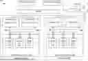
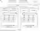


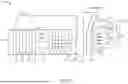
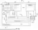
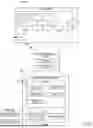
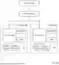


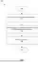


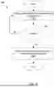


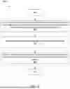
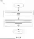

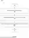
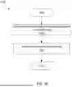
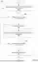


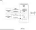

Sources:
- United States Patent and Trademark Office - verify current appl. status at the USPTO↗
Recent applications in this class:
- » 20260057086 2026-02-26
PROCESSING SYSTEM, PROCESSING METHOD, AND PROCESSING PROGRAM - » 20260057084 2026-02-26
PROXIMITY BASED AUTHENTICATION SYSTEM AND METHOD - » 20260057083 2026-02-26
BROWSER-BASED PROTECTION OF DATA FILES - » 20260057082 2026-02-26
INTERACTIVE OBFUSCATION AND INTERROGRATORIES - » 20260057081 2026-02-26
SYSTEMS AND METHODS FOR SELECTIVE ACCESS CONTROL FOR PORTIONS OF A BLOCKCHAIN - » 20260057080 2026-02-26
ENHANCED RAW DATA SECURITY - » 20260050678 2026-02-19
ELECTRONIC DEVICE AND METHOD FOR CONTROLLING ACCESS TO APPLET - » 20260050677 2026-02-19
WRITE PROTECT FUNCTION WITH SECURE CERTIFICATE AUTHENTICATION - » 20260050676 2026-02-19
Method for Providing a Digital Key - » 20260044614 2026-02-12
SEARCH MANAGEMENT DEVICE, COMPUTER SYSTEM, AND SEARCH MANAGEMENT METHOD