Fit Gripper
US20260061253A1
2026-03-05
19/263,993
2025-07-09
Smart Summary: Fit Gripper is a tool that helps improve hand grip strength while lifting weights. It has a spring-loaded lever that lets users exercise their fingers while holding onto weights. A collar clamp allows the lever to easily attach and detach from the weight bar. The design can be adjusted for different types of weights, like barbells or dumbbells. For heavier weights, it is made stronger, while a lighter version is available for easier use with lighter weights. 🚀 TL;DR
Abstract:
A removable grip strengthener for exercise weights. The present invention allows the user to exercise hand grip strength while simultaneously performing weight training exercises. The removable grip strengthener comprises a spring-loaded lever and a collar clamp. During lifting, the spring-loaded lever enables the user to train hand grip strength using one or more fingers while grasping the bar portion of the exercise weight with the remaining fingers. The collar clamp enables the spring-loaded lever to detachably connect to the bar portion of the exercise weight. The removable grip strengthener can be provided in multiple configurations to accommodate different types of exercise weights. For use with barbells, the present invention can include a more robust and rigid structure that provides greater resistance to the user exercising hand grip strength. For use with dumbbells, the present invention can include a lighter structure that is more practical to be used with lighter weights.
Applicant:
Interested in similar patents?
Get notified when new applications in this technology area are published.
Classification:
A63B23/16 » CPC main
Exercising apparatus specially adapted for particular parts of the body for limbs, i.e. upper or lower limbs, e.g. simultaneously for upper limbs or related muscles, e.g. chest, upper back or shoulder muscles for hands or fingers
A63B21/0726 » CPC further
Exercising apparatus for developing or strengthening the muscles or joints of the body by working against a counterforce, with or without measuring devices; User-manipulated weights; Dumb-bells, bar-bells or the like, e.g. weight discs having an integral peripheral handle Dumb bells, i.e. with a central bar to be held by a single hand, and with weights at the ends
A63B21/072 IPC
Exercising apparatus for developing or strengthening the muscles or joints of the body by working against a counterforce, with or without measuring devices; User-manipulated weights Dumb-bells, bar-bells or the like, e.g. weight discs having an integral peripheral handle
Description
FIELD OF THE INVENTION
The present invention generally relates to workout equipment and portable accessories. More specifically, the present invention discloses a portable workout device that can be attached to an exercise weight to strengthen the user's grip.
BACKGROUND OF THE INVENTION
Nowadays, many types of grip strengtheners have been made to help the user to strengthen their hand grip. In general, grip strengtheners are designed to be manually engaged using one hand by engaging two spring-loaded levers. The spring-loaded levers are connected to each other in such a way that the user can grab onto both levers using one hand. To exercise the grip, the user presses one lever against the other using all fingers, with the spring providing resistance against the pressing of the levers. This design allows grip strengtheners to be manufactured as portable devices that can be utilized anywhere. However, this design also prevents the user from utilizing the grip strengthener with other exercise equipment. For example, when lifting exercise weights, such as dumbbells, the user would benefit from also exercising their hand grip at the same time. Unfortunately, available grip strengtheners are not designed to be removably attached to an exercise weight. Some exercise equipment has been developed to include a grip strengthener. For example, some barbells have been designed with an integrated grip strengthener on the bar of the barbell. However, if the user does not want to utilize the grip strengthener, the user would not be able to remove the device since the grip strengthener is integrated into the structure of the bar. Therefore, a grip strengthener that can be removably attached to the bar portion of the exercise weight would be beneficial to the user.
An objective of the present invention is to provide a removable grip strengthener for exercise weights that enables the user to perform weight training while strengthening the hand grip. The present invention is designed to be removably attached to the bar portion of an exercise weight so that the user can train their hand grip strength while lifting the exercise weight. Another objective of the present invention is to provide a removable grip strengthener with a fastening mechanism that can be easily operated. The fastening mechanism of the present invention is designed to enable the user to easily fasten the device to the bar portion of the exercise weight without the use of other fasteners or devices. Another objective of the present invention is to provide a removable grip strengthener that can be provided in different designs to accommodate different exercise weights. The present invention can be designed for smaller bars of exercise weights, such as barbells, or larger bars of exercise weights, such as Olympic bars. Additional features and benefits of the present invention are further discussed in the sections below.
SUMMARY OF THE INVENTION
The present invention discloses a removable grip strengthener for exercise weights designed to be removably attached to the bar portion of the desired exercise weight. The present invention provides a portable exercise device that can be easily attached to the desired exercise weight to train hand grip strength while performing weight training. To do so, the present invention includes a spring-loaded lever and a collar clamp. The spring-loaded lever serves to help the user train hand grip strength while grabbing the bar of the exercise weight. The spring-loaded lever includes a handle portion that the user can safely engage with some fingers while still grabbing the bar with the remaining fingers. The handle portion includes a grip material that ensures the user safely grabs onto the handle portion to prevent injuries.
Further, the collar clamp is designed to be safely fastened to the bar of the exercise weight using different fastening mechanisms. For example, the fastening mechanism of the collar clamp can utilize a bolt with a wing nut that fastens the collar clamp to the bar of the exercise weight. Alternatively, the fastening mechanism can include a quick-release cam clamp that can be easily engaged by the user to fasten the collar clamp to the bar of the exercise weight. Further, the removable grip strengthener can be designed with different structural designs that can withstand different loads and that can be secured to different bars of exercise weights.
BRIEF DESCRIPTION OF THE DRAWINGS
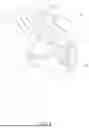
FIG. 1 is a top-front perspective view of a first embodiment of the present invention, shown in-use while attached to a barbell.
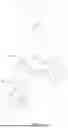
FIG. 2 is a top-front perspective view thereof, wherein the collar clamp is shown fastened without the barbell.
FIG. 3 is a top-rear perspective view thereof.
FIG. 4 is a bottom-front perspective view thereof.
FIG. 5 is a bottom-rear perspective view thereof.
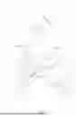
FIG. 6 is a top-front perspective view thereof, wherein the collar clamp is shown unfastened.
FIG. 7 is a top-rear perspective view thereof.
FIG. 8 is a bottom-front perspective view thereof.
FIG. 9 is a bottom-rear perspective view thereof.
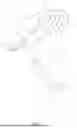
FIG. 10 is a front elevational view of a second embodiment of the present invention, shown-in use while attached to a dumbbell.
FIG. 11 is a top-front perspective view thereof, wherein the collar clamp is shown fastened without the dumbbell.
FIG. 12 is a top-rear perspective view thereof.
FIG. 13 is a bottom-front perspective view thereof.
FIG. 14 is a bottom-rear perspective view thereof.
FIG. 15 is a top-front perspective view thereof, wherein the collar clamp is shown unfastened.
FIG. 16 is a top-rear perspective view thereof.
FIG. 17 is a bottom-front perspective view thereof.
FIG. 18 is a bottom-rear perspective view thereof.
DETAIL DESCRIPTIONS OF THE INVENTION
All illustrations of the drawings are for the purpose of describing selected versions of the present invention and are not intended to limit the scope of the present invention.
The present invention discloses a removable grip strengthener 1 for exercise weights that enables the user to exercise hand grip strength while performing weight training exercises with the exercise weights. As can be seen in FIG. 1 through 18, the present invention can be provided with different structural designs that accommodate different designs of exercise weights. Each embodiment of the present invention can be designed to withstand different loads and accommodate different bar structures. For example, a first embodiment of the present invention can include a more robust and rigid structure that provides greater resistance to the user exercising the hand grip strength. A second embodiment of the present invention can include a lighter structure that is more practical to be used with lighter exercise weights.
In general, the present invention comprises a spring-loaded lever 2 and a collar clamp 3. The spring-loaded lever 2 enables the user to train hand grip strength while grabbing the bar portion 91 of the exercise weight 9 when the user lifts the exercise weight. The collar clamp 3 enables the spring-loaded lever 2 to removably attach to the bar portion 91 of the desired exercise weight. The collar clamp 3 allows the user to adjust the positioning of the spring-loaded lever 2 so that the spring-loaded lever 2 coincides with the positioning of the user's hand on the bar portion of the exercise weight 9.
The general configuration of the aforementioned components enables the user to safely perform weight training exercises while training the grip strength simultaneously. As can be seen in FIG. 1 through 18, the spring-loaded lever 2 is designed to facilitate the training of the user's hand grip by providing resistance when the user presses the spring-loaded lever 2 against the bar portion of the exercise weight. In general, the spring-loaded lever comprises an elongated rod 21, a handle 22, and a torsion spring 23. The elongated rod 21 supports the handle 22 and connects the handle to the torsion spring 23. The handle 22 provides a comfortable area for the user to engage the spring-loaded lever 2 using one or more fingers when exercising. The torsion spring 23 provides the resistance necessary for the user to train the hand grip strength.
As can be seen in FIG. 1 through 18, the spring-loaded lever 2 can be arranged as follows: the elongated rod 21 comprises a first rod end 21a and a second rod end 21b corresponding to the terminal ends of the elongated rod 21. The first rod end 21a is terminally connected to a proximal end 23a of the torsion spring 23, while the second rod end 21b is left free. Further, a distal end 23b of the torsion spring 23 is connected onto the collar clamp 3, thereby securing the spring-loaded lever 2 to the collar clamp 3. The handle 22 is mounted onto the elongated rod 21, adjacent to the second rod end 21b, thereby securing the handle to the elongated rod. As can be seen in FIG. 1, the positioning of the handle 22 is set so that when the use grabs onto the bar portion 91 of the exercise weight 9, the user can reach and grab onto the handle 22 of the spring-loaded lever 2 as well.
As best seen in FIG. 2, the elongated rod 21 is preferably oriented at an acute angle with the top surface of the collar clamp 3 so that the handle 22 can be easily grabbed onto with one or more fingers while holding onto the bar portion 91 of the exercise weight 9. For example, as seen in FIG. 10, the user can secure the collar clamp 3 near the weight portion 92 of the exercise weight 9, with the elongated rod 21 and the handle 22 being oriented away from the weight portion 92. The user can then first grab onto the bar portion 91 of the exercise weight 9 by wrapping one or more fingers around the bar portion 91, extending the hand towards the handle 22 of the spring-loaded lever, and then grabbing onto the handle 22 with one or more free fingers. The user can use four fingers to grab onto the bar portion 91 and one finger to hold onto the handle 22 of the spring-loaded lever, or vice versa.
As previously discussed, the present invention can be provided in different configurations to accommodate specific requirements. As can be seen in FIG. 1 through 9, in the first embodiment, the spring-loaded lever 2 is connected to the collar clamp 3 in a fixed position. In this embodiment, the handle 22 is preferably a removable metal handle that can be fastened along the elongated rod 21 adjacent to the second rod end 21b. The position of the handle 22 along the elongated rod 21 can be adjusted incrementally according to the user's preferences. More specifically, the handle 22 comprises a receiver opening 20 that traverses axially into the handle 22 from the distal end 22a of the handle. The second rod end 21b is configured to slidably engage with the receiver opening 20 and detachably connect to the handle 22. The handle can then be adjusted along the length of the elongated rod 21 by way of detents, annular grooves, or any other known technique in the industry. Further, the handle 22 may include a knurled outer surface that increases the grip of the user's fingers on the handle to increase the safety of the user. In other embodiments, different grip features can be provided on the metal handle 22.
As can be seen in FIG. 10 through 18, in the second embodiment, the spring-loaded lever 2 can be rotatably connected onto the collar clamp in a fixed location. In this embodiment, the handle 22 is preferably a foam grip handle that surrounds the elongated rod 21 near the second rod end 21b. For some users, this arrangement is more ergonomic and comfortable to grab using one or more fingers as compared to the first embodiment. Further, unlike the metal handle version, the foam grip handle 22 of the second embodiment is fixed in position on the elongated rod 21 adjacent to the second rod end 21b. In other embodiments, other soft materials can be implemented to replace the foam grip handle 22.
Similar to the spring-loaded handle 2, the collar clamp 3 can also be provided in different configurations to accommodate different user requirements. As can be seen in FIG. 1 through 9 of the first embodiment, the collar clamp 3 is a sturdy clamp that can be secured to the bar portion 91 of the exercise weight 9 using a bolt and a wing nut. To do so, the first embodiment of the collar clamp 3 comprises an upper flange 4, a lower flange 5, and a clamp mechanism 6. The upper flange 4 and the lower flange 5 correspond to arc-shaped structures with an inner diameter matching the outer diameter of the bar portion 91 of an exercise weight 9. In addition, the upper flange 4 and the lower flange 5 each comprise a first end 41,51 and a second end 42,52 corresponding to the terminal ends of each flange. The first end 41 of the upper flange 4 is hingedly connected to the first end 51 of the lower flange 5. The clamp mechanism 6 secures the second end 42 of the upper flange 4 to the second end 52 of the lower flange 5 in a closed position.
Continuing with the first embodiment, the clamp mechanism 6 is in the form of a screw clamp 60. The screw clamp 60 comprises a bolt fastener 61 and a wing nut 65. The head 62 of the bolt fastener is terminally and hingedly connected to the second end 42 of the upper flange 4. The bolt fastener 61 is also centered on the second end 42 of the upper flange 4. This arrangement enables the bolt fastener 61 to pivot and swing towards or away from the lower flange 5 while in the open position. Further, the second end 52 of the lower flange 5 is notched to clear the bolt fastener 61 while in the closed position. More specifically, the second end 52 of the lower flange 5 comprises a bolt cutout 53 with a size and shape matching the size and shape of the bolt fastener 61. The bolt cutout 53 is also positioned on the lower flange 5 to align with the bolt fastener 61 on the upper flange 4. This way, when the user wants to fasten the collar clamp 3 around the bar portion 91 of the desired exercise weight 9, the user first positions the upper flange 4 around the bar portion 91. Then, the user closes the collar clamp 3 by positioning the lower flange 5 around the bar portion 91. Specifically, the second end 52 of the lower flange 5 is rotated until adjacent to the second end 42 of the upper flange 4. This enables the bolt fastener 61 to be rotated into the bolt cutout 53. Finally, to secure the connection, the wing nut 65 is threadedly engaged along the distal end 63 of the bolt fastener 61. The wing nut 65 is then tightened until fully pressed against the lower flange 5. Thus, the wing nut 65 secures the second end 42 of the upper flange 4 with the second end 52 of the lower flange 5 in a closed configuration, thereby securing the present invention onto the exercise weight 9.
As previously discussed, the spring-loaded lever 2 is fixed in positioned on the collar clamp 3. As can be seen in FIG. 1 through 9, the upper flange 4 further comprises a spring slot 43 configured to receive a distal end 23b of the torsion spring 23, which in turn, secures the torsion spring to the upper flange 4 of the collar clamp 3. For clarity, the distal end 23b of the torsion spring 23 is opposite to the connection at the elongated rod 21. The distal end 23b of the torsion spring is preferably adapted to fit the spring slot 43. More specifically, the distal end 23b is shaped into a rectangular, elongated protrusion that fits into the spring slot 43 on the upper flange 4, which is also rectangular shaped.
The spring slot 43 is preferably centered on the concave side of the upper flange 4, which positions the torsion spring 23 against the bar portion 91 of the exercise weight when the collar clamp 3 is fastened to the bar portion. Stated another way, the spring slot 43 is laterally integrated onto the inside surface 44 of the upper flange 4, preferably centered between the first and second ends 41,42 of the upper flange. Further, a threaded fastener 8 can be utilized to fully secure the distal end 23b of the torsion spring 23 to the upper flange 4. As best seen in FIG. 6, a hex bolt fastener 8 extends through an aperture 45 from the outside surface 46 of the upper flange 4 and fastens into the distal end 23b of the torsion spring 23. In other embodiments, the spring-loaded lever 2 can be fully secured onto the collar clamp 3 using any other suitable means of attachment.
As can be seen in FIGS. 10 through 18 of the second embodiment, the lighter version of the collar clamp 3 can be easily fastened using a quick-release system. Similar the first embodiment, the second embodiment of the collar clamp 3 comprises an upper flange 4 and a lower flange 5. The upper flange 4 and the lower flange 5 correspond to arc-shaped structures with an inner diameter matching the outer diameter of the bar portion 91 of an exercise weight 9 selected by the user. In addition, the upper flange 4 and the lower flange 5 each comprise a first end 41,51 and a second end 42,52 corresponding to the terminal ends of each flange. The first end 41 of the upper flange 4 is hingedly connected to the first end 51 of the lower flange 5.
But unlike the first embodiment which utilizes a screw-type clamp for attaching onto the exercise weight 9, the second embodiment utilizes a quick-release lever. More specifically, the clamp mechanism 6 of the second embodiment is in the form of a cam clamp 70. The cam clamp 70 comprises a cam bolt 71 and a cam lever 75. As best seen in FIG. 18, the head 72 of the cam bolt is terminally and hingedly connected to the second end 42 of the upper flange 4. As best seen in FIG. 14, a base 76 of the cam lever is threadedly engaged with the distal end 73 of the cam bolt 71. As will be explained further, this arrangement enables the user to adjust the opening diameter of the collar clamp 3 to accommodate various size bars on exercise weights 9.
As can be seen in FIGS. 10 through 18, the second end 52 of the lower flange 5 is notched to clear the cam bolt 71 while in the closed position. More specifically, the second end 52 of the lower flange 5 comprises a bolt cutout 53 with a size and shape matching the size and shape of the cam bolt 71. The bolt cutout 53 is also positioned on the lower flange 5 to align with the cam bolt 71 on the upper flange 4. This way, when the user wants to fasten the collar clamp 3 around the bar portion 91 of the desired exercise weight 9, the user first positions the upper flange 4 around the bar portion 91. Then, the user closes the collar clamp 3 by positioning the lower flange 5 around the bar portion 91. Specifically, the second end 52 of the lower flange 5 is rotated until adjacent to the second end 42 of the upper flange 4. This enables the cam bolt 71 to be rotated into the bolt cutout 53. Finally, to secure the connection, the cam lever 75 is pressed against the lower flange 5 which presses the lower flange 5 against the upper flange 4.
As can be seen in FIG. 10 through 18 of the second embodiment, the spring-loaded lever 2 can be fixed in position on the upper flange 4 in such a way that the spring-loaded lever 2 can be rotated to adjust the orientation of the spring-loaded lever 2. To enable this function, the distal end 23b of the torsion spring 23 traverses through an opening in the upper flange 4 and is rotatably connected to the cam bolt 71. This arrangement allows the user to adjust the orientation of the spring-loaded lever 2 as needed for proper grip. For example, the user can adjust the orientation of the spring-loaded lever 2 before securing the collar clamp 3 onto the bar portion 91 of the exercise weight.
The working length of the cam bolt 71 can also be adjusted by tightening or loosening the cam lever 75 along the cam bolt 71 to accommodate smaller bars of exercise weights 9. Once the working length of the cam bolt 71 is achieved, the user can then engage the cam clamp 70 to secure the collar clamp 3 around the bar portion 91 of the exercise weight. In other embodiments, the collar clamp 3 can be modified to include various clamp mechanisms that can be quickly engaged and/or disengaged. Also in other embodiments, the spring-loaded lever 2 can be permanently fixed onto the upper flange 4.
Although the invention has been explained in relation to its preferred embodiment, it is to be understood that many other possible modifications and variations can be made without departing from the spirit and scope of the invention.
Claims
What is claimed is:1. A detachable grip strengthener comprising:
a spring-loaded lever;
a collar clamp;
the spring-loaded lever being connected to the collar clamp;
the spring-loaded lever comprising an elongated rod, a handle, and a torsion spring;
the elongated rod comprising a first rod end and a second rod end;
the first rod end being terminally connected to a proximal end of the torsion spring;
the second rod end being connected to the handle;
a distal end of the torsion spring being connected to the collar clamp; and
the collar clamp capable of detachably connecting to the bar portion of an exercise weight.
2. The detachable grip strengthener as claimed in claim 1 comprising:
the collar clamp comprising an upper flange, a lower flange, and a clamp mechanism;
a first end of the upper flange being hingedly connected to a first end of the lower flange; and
the clamp mechanism being configured to secure a second end of the upper flange to a second end of the lower flange in a closed position.
3. The detachable grip strengthener as claimed in claim 2, wherein the clamp mechanism is in the form of a screw clamp.
4. The detachable grip strengthener as claimed in claim 3 comprising:
the screw clamp comprising a bolt fastener and a wing nut;
the second end of the upper flange being hingedly connected to the head of the bolt fastener;
the second end of the lower flange being notched to clear the bolt fastener;
the wing nut being threadedly engaged with the bolt fastener; and
the wing nut being configured to secure the second end of the upper flange to the second end of the lower flange.
5. The detachable grip strengthener as claimed in claim 3 comprising:
a spring slot being laterally integrated onto an inside surface of the upper flange;
the distal end of the torsion spring being adapted to fit the spring slot; and
the distal end of the torsion spring being detachably connected to the upper flange.
6. The detachable grip strengthener as claimed in claim 5 comprising:
a threaded fastener; and
the threaded fastener extending through an aperture on the outside surface of the upper flange and fastened into the distal end of the torsion spring.
7. The detachable grip strengthener as claimed in claim 3 comprising:
the handle being constructed of metal;
a receiver opening traversing axially into a distal end of the handle; and
the second rod end being fastened to the handle through the receiver opening.
8. The detachable grip strengthener as claimed in claim 2, wherein the clamp mechanism is in the form of a cam clamp.
9. The detachable grip strengthener as claimed in claim 8 comprising:
the cam clamp comprising a cam bolt and a cam lever;
the second end of the upper flange being hingedly connected to the head of the cam bolt;
the second end of the lower flange being notched to clear the cam bolt;
a base of the cam lever being threadedly engaged with the cam bolt; and
the cam lever being configured to secure the second end of the upper flange to the second end of the lower flange.
10. The detachable grip strengthener as claimed in claim 9, wherein the distal end of the torsion spring extends through the upper flange and rotatably connects to the cam bolt.
11. The detachable grip strengthener as claimed in claim 8 comprising:
the handle being a foam grip; and
the foam grip being fixedly attached to the elongated rod.
12. A detachable grip strengthener comprising:
a spring-loaded lever;
a collar clamp;
the spring-loaded lever being connected to the collar clamp;
the spring-loaded lever comprising an elongated rod, a handle, and a torsion spring;
the elongated rod comprising a first rod end and a second rod end;
the first rod end being terminally connected to a proximal end of the torsion spring;
the second rod end being connected to the handle;
a distal end of the torsion spring being connected to the collar clamp;
the collar clamp comprising an upper flange, a lower flange, and a clamp mechanism;
a first end of the upper flange being hingedly connected to a first end of the lower flange;
the clamp mechanism being configured to secure a second end of the upper flange to a second end of the lower flange in a closed position;
the clamp mechanism being in the form of a screw clamp; and
the collar clamp capable of detachably connecting to the bar portion of an exercise weight.
13. The detachable grip strengthener as claimed in claim 12 comprising:
the screw clamp comprising a bolt fastener and a wing nut;
the second end of the upper flange being hingedly connected to the head of the bolt fastener;
the second end of the lower flange being notched to clear the bolt fastener;
the wing nut being threadedly engaged with the bolt fastener; and
the wing nut being configured to secure the second end of the upper flange to the second end of the lower flange.
14. The detachable grip strengthener as claimed in claim 12 comprising:
a spring slot being laterally integrated onto an inside surface of the upper flange;
the distal end of the torsion spring being adapted to fit the spring slot; and
the distal end of the torsion spring being detachably connected to the upper flange.
15. The detachable grip strengthener as claimed in claim 14 comprising:
a threaded fastener; and
the threaded fastener extending through an aperture on the outside surface of the upper flange and fastened into the distal end of the torsion spring.
16. The detachable grip strengthener as claimed in claim 12 comprising:
the handle being constructed of metal;
a receiver opening traversing axially into a distal end of the handle; and
the second rod end being fastened to the handle through the receiver opening.
17. A detachable grip strengthener comprising:
a spring-loaded lever;
a collar clamp;
the spring-loaded lever being connected to the collar clamp;
the spring-loaded lever comprising an elongated rod, a handle, and a torsion spring;
the elongated rod comprising a first rod end and a second rod end;
the first rod end being terminally connected to a proximal end of the torsion spring;
the second rod end being connected to the handle;
a distal end of the torsion spring being connected to the collar clamp;
the collar clamp comprising an upper flange, a lower flange, and a clamp mechanism;
a first end of the upper flange being hingedly connected to a first end of the lower flange;
the clamp mechanism being configured to secure a second end of the upper flange to a second end of the lower flange in a closed position;
the clamp mechanism being in the form of a cam clamp;
the cam clamp comprising a cam bolt and a cam lever;
the second end of the upper flange being hingedly connected to the head of the cam bolt;
the second end of the lower flange being notched to clear the cam bolt;
a base of the cam lever being threadedly engaged with the cam bolt;
the cam lever being configured to secure the second end of the upper flange to the second end of the lower flange; and
the collar clamp capable of detachably connecting to the bar portion of an exercise weight.
18. The detachable grip strengthener as claimed in claim 17, wherein the distal end of the torsion spring extends through the upper flange and rotatably connects to the cam bolt.
19. The detachable grip strengthener as claimed in claim 17 comprising:
the handle being a foam grip; and
the foam grip being fixedly attached to the elongated rod.
Images & Drawings included:


Sources:
- United States Patent and Trademark Office - verify current appl. status at the USPTO↗
Similar patent applications:
- » 20100084882
Clamping element for fitting on a clamping tongue of a gripper as well as gripper fitted with such a clamping element - » 12430433
Push to connect fitting with formed gripper teeth - » 20210033231
Push-to-connect-rotate-to-release sprinkler assembly and fitting with helical gripper ring - » 14575776
Media substrate gripper including a plurality of snap-fit fingers - » 15168014
Gripper for manipulating planar workpiece in tight-fitting receptacle - » 14986093
Gripper for manipulating planar workpiece in tight-fitting receptacle - » 20250050572
Gripper For A Draping Frame And For A Device, Draping Frame, Device And Method For The Forming Of And/Or Covering Using A Film Element, System For Manufacturing A Moulded Part Or A Covered Component, Method For Retro-Fitting A Device Of This Type, Method For Manufacturing A Covered Component - » 20220040904
Gripper for a draping frame and for a device, draping frame, device and method for the forming of and/or covering using a film element, system for manufacturing a moulded part or a covered component, method for retro-fitting a device of this type, method for manufacturing a covered component - » 20230138039
Gripper for a draping frame and for a device, draping frame, device and method for the forming of and/or covering using a film element, system for manufacturing a moulded part or a covered component, method for retro-fitting a device of this type, method for manufacturing a covered component
Recent applications in this class:
- » 20260014417 2026-01-15
Hand Grip Strengthener - » 20260014416 2026-01-15
Multi-Resistance Hand Gripper Ring - » 20250367503 2025-12-04
Multi-Orientation Nesting Grip Training Handle - » 20250367502 2025-12-04
CIRCULAR ANNULAR TRAINING EQUIPMENT - » 20250345655 2025-11-13
MULTI-FUNCTIONAL APPARATUS, KIT, AND METHOD FOR DEXTERITY ENHANCEMENT - » 20250319354 2025-10-16
HAND EXERCISE REHABILITATION SYSTEM AND METHOD - » 20250303231 2025-10-02
Therapeutic Glove - » 20250295952 2025-09-25
Palm Leverage Handheld Body Strengthening Apparatus - » 20250177814 2025-06-05
GRIP STRENGTH TRAINING AND MEASURING DEVICE - » 20250153000 2025-05-15
GRIP TRAINING SYSTEM