FINDING SUBSTRATE NOTCH ON SUBSTRATE IN A CHEMICAL MECHANICAL POLISHING SYSTEM
US20260061553A1
2026-03-05
18/820,182
2024-08-29
Smart Summary: A polishing system has different parts to help find a notch on a substrate. It includes a station for polishing, a station for finding the notch, and a system to move the substrate between these stations. At the notch finding station, a special holder keeps the substrate in place while a liquid is introduced to create a column of liquid above it. A light beam is directed through this liquid onto the substrate, and the system captures the reflections of the light to detect the notch. This setup helps ensure accurate polishing by identifying the exact location of the notch on the substrate. 🚀 TL;DR
Abstract:
A polishing apparatus has a polishing station, a notch finding station, and a substrate handling system to move a substrate therebetween. The substrate handling system includes a carrier to hold a substrate at the notch finding station. The notch finding station includes a housing including floor and sidewalls that form an open-topped reservoir, the sidewalls having a lower portion and an upper portion having an upper edge that is thinner than the lower portion, a passage to introduce a liquid into the open-topped reservoir to form a liquid column extending to the substrate, and an optical fiber extending through a floor of the housing and positioned to direct a light beam through the liquid column onto the substrate when held by the carrier at the notch finding station and to receive reflections of the light beam from the substrate.
Inventors:
- Justin Ho Kuen Wong 9 🇺🇸 Pleasanton, CA, United States
- Emily Augason 3 🇺🇸 San Mateo, CA, United States
- Tom C. Chen 2 🇺🇸 Sunnyvale, CA, United States
Applicant:
Interested in similar patents?
Get notified when new applications in this technology area are published.
Classification:
B24B49/12 » CPC main
Measuring or gauging equipment for controlling the feed movement of the grinding tool or work; Arrangements of indicating or measuring equipment, e.g. for indicating the start of the grinding operation involving optical means
B24B37/27 » CPC further
Lapping machines or devices; Accessories Work carriers
Description
TECHNICAL FIELD
This disclosure relates to detecting the angular position of a substate, such as the position of a substrate notch, in a chemical mechanical polishing (CMP) system.
BACKGROUND
An integrated circuit is typically formed on a substrate by the sequential deposition of conductive, semiconductive, or insulative layers on a silicon wafer. One fabrication step involves depositing a filler layer over a non-planar surface and planarizing the filler layer. For certain applications, the filler layer is planarized until the top surface of a patterned layer is exposed. A conductive filler layer, for example, can be deposited on a patterned insulative layer to fill the trenches or holes in the insulative layer. After planarization, the portions of the metallic layer remaining between the raised pattern of the insulative layer form vias, plugs, and lines that provide conductive paths between thin film circuits on the substrate. For other applications, such as oxide polishing, the filler layer is planarized until a predetermined thickness is left over the non-planar surface. In addition, planarization of the substrate surface is usually required for photolithography.
Chemical mechanical polishing (CMP) is one accepted method of planarization. This planarization method typically requires that the substrate be mounted on a carrier or polishing head. The exposed surface of the substrate is typically placed against a rotating polishing pad. The carrier head provides a controllable load on the substrate to push it against the polishing pad. An abrasive polishing slurry is typically supplied to the surface of the polishing pad.
SUMMARY
In one aspect, a polishing apparatus has a polishing station, a notch finding station, and a substrate handling system to move a substrate between the polishing station and the notch finding station. The substrate handling system includes a carrier to hold a substrate at the notch finding station. The notch finding station includes a housing including floor and sidewalls that form an open-topped reservoir, the sidewalls having a lower portion and an upper portion having an upper edge that is thinner than the lower portion, a passage to introduce a liquid into the open-topped reservoir to form a liquid column extending to the substrate, and an optical fiber extending through a floor of the housing and positioned to direct a light beam through the liquid column onto the substrate when held by the carrier at the notch finding station and to receive reflections of the light beam from the substrate.
In another aspect, a polishing apparatus has a polishing station, a notch finding station, a substrate handling system to move a substrate between the polishing station and the notch finding station and including a carrier hold a substrate at the notch finding station. The notch finding station includes a housing including floor and sidewalls that form an open-topped reservoir, a passage to introduce a liquid into the open-topped reservoir to form a liquid column extending to the substrate, and an optical fiber extending through a floor of the housing and positioned to direct a light beam through the liquid column onto the substrate when held by the carrier at the notch finding station and to receive reflections of the light beam from the substrate. A liquid source supplies the liquid, and a controller is configured to cause the liquid source to flow the liquid at a first flow rate when the notching finding station is operating to detect a notch and at a second reduced non-zero flow rate when the notching finding station is idling.
In another aspect, a polishing apparatus has a polishing station, a notch finding station, and a substrate handling system to move a substrate between the polishing station and the notch finding station and including a carrier hold a substrate at the notch finding station. The notch finding station includes a housing having an internal volume that provides forms a reservoir with a floor, a ceiling, and first sidewalls that extend from the floor to the ceiling. An aperture extends through the ceiling of the reservoir and a side-passage extends laterally from a region of the reservoir below the aperture to an entry port such that a liquid injected through the entry port flows through the side-passage into the region below the aperture and forms a liquid column that emerges from the reservoir through the aperture. An optical fiber extends through a floor of the reservoir and positioned to direct a light beam through the aperture and through the liquid column onto the substrate when held by the carrier at the notch finding station and to receive reflections of the light beam from the substrate.
In another aspect, a polishing apparatus has a polishing station, a notch finding station, and a substrate handling system to move a substrate between the polishing station and the notch finding station and including a carrier hold a substrate at the notch finding station. The notch finding station includes a housing having an internal volume that provides forms a reservoir with a floor, a ceiling, and first sidewalls that extend from the floor to the ceiling. An aperture extends through the ceiling of the reservoir such that a liquid injected into the reservoir flows forms a liquid column that emerges from the reservoir through the aperture. A cylindrical inner second sidewall projects upwardly from the floor of the reservoir, and an optical fiber extends through the floor of the reservoir with the cylindrical inner second sidewall surrounding the optical fiber. The optical fiber is positioned to direct a light beam through the aperture and through the liquid column onto the substrate when held by the carrier at the notch finding station and to receive reflections of the light beam from the substrate.
Implementations may include one or more of the following potential advantages. The notch of a substrate may be detected with high accuracy in a wet environment. An issue with the wet environment is that there might be liquid droplets near the substrate edges (e.g., in the grooves of a retaining ring) that have a different light refractive index than air. The liquid droplets can scatter a light beam used for notch detection and thus result in inaccurate reading of a substrate notch. However, a liquid column pointing upward towards the substrate may provide a consistent medium with a uniform refractive index. The uniform refractive index may enable a light beam to travel efficiently inside the liquid column with reduced signal distortion, both when travelling towards and when reflected from the substrate. In addition, wafer notch detection may be enabled without a need to remove the substrate from a carrier, which streamlines the manufacturing process and reduces manufacture cost.
The details of one or more implementations are set forth in the accompanying drawings and the description below. Other aspects, features and advantages will be apparent from the description and drawings, and from the claims.
DESCRIPTION OF DRAWINGS
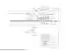
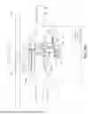
FIG. 1 is a schematic plan view of an example of a polishing apparatus.
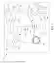
FIG. 2 is a schematic cross-sectional view of an example of a polishing apparatus.
FIGS. 3A and 3B are schematic top views of substrates with different notches.
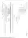
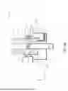
FIG. 4A is a schematic side view of a first implementation of an inter-platen notch finding station.
FIG. 4B is an enlarged view of the first implementation of the notch finding station of FIG. 4A.
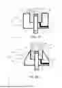
FIG. 4C is schematic cross-sectional view of a second implementation of a notch finding station.
FIG. 4D is a schematic cross-sectional view of a third implementation of a notch finding station.
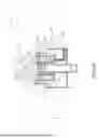
FIG. 4E is a schematic cross-sectional view of a fourth implementation of a notch finding station.
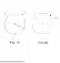
FIG. 4F is a schematic cross-sectional view of a fifth implementation of a notch finding station.
FIG. 4G is a schematic cross-sectional view of the implementation of FIG. 4F through line A-A.
FIG. 5A is a schematic bottom view of a substrate and a retaining ring showing a path of a sensing region along a circumference of the substrate.
FIG. 5B is an illustrative graph of intensity of reflected light as a function of an angular position of a carrier head in a dry measurement environment.
FIG. 5C is an illustrative graph of intensity of reflected light as a function of an angular position of a carrier head in a wet measurement environment before and after a liquid column is turned on.
FIG. 6 is an illustrative graph of flow rate of a liquid flowed from a liquid source during a start-up process.
DETAILED DESCRIPTION
In some polishing operations the substrate is held by a rotating carrier head and pressed against the rotating polishing pad. Rotation of the carrier head imparts rotation to the substrate.
For some processes, it is useful to have each substrate oriented to a consistent angular position before polishing commences. If the polishing operation has some inherent angular variation, e.g., due to a pattern of features on the substrate, then a consistent starting angular position can improve the ability of the polishing system to compensate for such variation, e.g., by application of appropriate pressures by the chambers inside the carrier head. In addition, a consistent starting angular position can improve the likelihood that a thickness sensor traces a consistent series of paths across the substrate on a wafer-to-wafer basis, thus making processing of the thickness measurement signal from the in-situ monitoring system more reliable.
One method to measure the angular position is to conduct a measurement before a polishing operation or between two separate polishing operations, e.g., at a station positioned between two platens of the polishing system, with a light beam. A light source can be positioned below the substrate with an air gap between the substrate and sensor. The light beam can be emitted from the light source and propagate in the air towards the edge of the substrate. A detector can measure an intensity of the reflected light. During this process, the carrier head can rotate. When the notch passes through the illuminated spot, the amount of reflected light should change, e.g., drop. This intensity of the reflected beam can be used to detect the wafer notch on a dry substrate and in a dry environment. However, this technique may be susceptible to noise in a wet environment. Here a “wet” environment generally refers to the possible presence of liquid droplets in the system atmosphere, e.g., slurry droplets scattered by the carrier head or other components, aerosolized water from a rinse system that sprays the polishing pad, condensed steam from a heating system, etc. An issue with the wet environment is that liquid droplets can be deposited on or near the substrate edges (e.g., on the substrate itself, on the carrier head membrane, or in the grooves of the retaining ring) that have different light refractive index than air. The water droplets can scatter the light beam when the light beam enters the liquid from air and thus result in inaccurate reading of substrate notches.
A technique to address this problem includes deploying a liquid column that points upward towards the substrate to submerge the light beam. The notch finding light beam travels only in one consistent medium (e.g., liquid) and thus the light beam would not be scattered due to differing reflective index between the liquid and air. Less scattering improves measurement precision. In addition, the liquid column can protect the optical fiber from environmental contaminants (e.g., chemical splashing from the nearby polishing platens), enhancing its operation life. Further, these techniques enable detection of the substrate notch with the substrate being held on a carrier head. Not requiring any additional operation to remove the substrate from the carrier head for notch detection enhances manufacturing efficiency and helps reduce manufacturing costs associated with operations.
FIG. 1 is a plan view of a chemical mechanical polishing apparatus 100 for processing one or more substrates. FIG. 2 is a schematic cross-sectional view of an example of an example polishing station 110. For ease of description, reference will be made to both figures when describing the chemical mechanical polishing apparatus 100.
The polishing apparatus 100 includes a plurality of polishing stations 110. For example, the polishing apparatus can include three polishing stations 110a, 110b, and 110c. The polishing apparatus 100 also includes at least one carrier head 140, e.g., four carrier heads 140. The polishing apparatus 100 also includes a transfer station 104 for loading and unloading substrates from the carrier heads 140. The stations of the polishing apparatus 100, including the transfer station 104 and the polishing stations 110, can be positioned at substantially equal angular intervals around the center of the platform.
Referring to FIG. 2, each polishing station 110 includes a polishing pad 130 supported on a rotatable platen 120. The polishing pad 130 can be a two-layer polishing pad with an outer polishing layer 132 and a softer backing layer 134. A top surface of the polishing layer 132 can provide a polishing surface 136.
Returning to FIG. 1, for a polishing operation, one carrier head 140 is positioned at each polishing station 110. Another additional carrier head 140 can be positioned in the transfer station 104 to exchange a polished substrate for an unpolished substrate while the other substrates are being polished at the polishing stations 110.
The carrier heads 140 are held by a support structure 150, e.g., a rotatable carousel or a carriage suspended from a track, that can cause carrier head to move along a 106 path that passes, in order, each polishing station 110a-110c and the transfer station 104. The support structure 150 and the carrier heads 140 can also be referred to as a substrate handling system 175 in this disclosure.
Referring to FIGS. 1 and 2, each polishing station 110 can include a port 160, e.g., at the end of an arm 162, to dispense polishing liquid 164, such as abrasive slurry, onto the polishing pad 130. Each polishing station 110 of the polishing apparatus 100 can also include pad conditioning apparatus 170 to abrade the polishing pad 130 to maintain the polishing surface 136 in a consistent abrasive state. For example, the conditioning apparatus can include a conditioning head 172 with a conditioning disk at the end of an arm 174.
As shown in FIG. 2, the platen 120 at each polishing station 110 is operable to rotate about an axis 122. For example, a motor 124 can turn a drive shaft 126 to rotate the platen 120.
Each carrier head 140 is operable to hold a substrate 10 against the polishing pad 130. Each carrier head 140 can include a retaining ring 142 to retain the substrate 10 below a flexible membrane 144. Each carrier head 140 can also include a plurality of independently controllable pressurizable chambers defined by the membrane, e.g., three chambers 146a-146c, that can apply independently controllable pressurizes to associated zones on the flexible membrane 144 and thus on the substrate 10. Although only three chambers are illustrated in FIG. 2 for ease of illustration, there could be one or two chambers, or four or more chambers, e.g., five chambers.
Each carrier head 140 is suspended from the support structure 150, and is connected by a drive shaft 154 to a carrier head rotation motor 156 so that the carrier head can rotate about an axis 152. Optionally each carrier head 140 can oscillate laterally, e.g., driven by a carriage on the track, by a motor that oscillates the carrier head radially, or by rotational oscillation of the carousel itself.
In operation, the platen 120 is rotated about its central axis 122, and each carrier head 140 is rotated about its central axis 152 and translated laterally across the top surface of the polishing pad 130.
An in-situ monitoring system can include a sensor 180 installed in the platen 120 to monitor the progress of the polishing operation and/or measure a thickness of the layer on the substrate 10 that is being polished. The sensor 180 could be an optical sensor, e.g., a spectrometer, an eddy current sensor, a capacitive sensor, a friction sensor, etc.
A controller 190, such as a programmable computer, is connected to each motor 124, 156 to independently control the rotation rate of the platen 120 and the carrier heads 140. For example, each motor 156 can include an encoder 158 that measures the angular position or rotation rate of the associated drive shaft 154. The associated drive shafts can have respective reference angular positions that are recognized by the encoder 158 to measure the number of revolutions of the drive shafts.
The controller 190 is also connected to pressure regulators to control the pressures in the chambers 146a-146c. In particular, the controller 190 can be configured to receive thickness measurements from the in-situ monitoring system and control the pressures in the chambers 146a-146c to provide improved polishing uniformity.
The controller 190 can include a central processing unit (CPU) 192, a memory 194, and support circuits 196, e.g., input/output circuitry, power supplies, clock circuits, cache, and the like. The memory is connected to the CPU 192. The memory is a non-transitory computable readable medium, and can be one or more readily available memory such as random access memory (RAM), read only memory (ROM), floppy disk, hard disk, or other form of digital storage. In addition, although illustrated as a single computer, the controller 190 could be a distributed system, e.g., including multiple independently operating processors and memories.
As noted above, for some processes, it is useful to have each substrate 10 oriented to a consistent angular position before polishing commences. The substrate 10 to be polished generally includes a notch that allows the substrate 10 to be angularly oriented, for example, by a specific angle from the notch. The notch provides a fiducial that is generally defined by removal of a portion of the substrate 10. For example, as shown in FIGS. 3A-3B, a circular substrate 10 can have a notch 12 formed by the removal of a portion from the edge 14 of the substrate 10. The substrate 10 can have a diameter D1 of 200 mm or 300 mm. As shown in FIG. 3A, the notch 12 can be triangular (with or without a rounded apex) in shape. Such a notch 12 can be relatively small, e.g., about 1 mm in depth from the substrate edge 14 and about 3 mm wide along the circumference (the size is significantly exaggerated in FIG. 3A for clarity). Alternatively, as shown in FIG. 3B, the notch 12ʹ can be a “flat.”
Referring back to FIG. 1, the polishing apparatus 100 can also include one or more notch-finding stations 200. In some implementations, a notch-finding station 200a is positioned on the path 106 at a spot between the transfer station 104 and a first polishing station, e.g., polishing station 110a. One or more notch-finding stations 200b, 200c can be positioned on the path 106 travelled by the carrier heads 140 between two polishing stations 110.
In some implementations, the polishing system includes two or more inter-platen notch-finding stations 200b, 200c. If there are two notch-finding stations, the two inter-platen notch-finding stations 200b, 200c could be on the path 106 on opposite sides of a polishing station, e.g., the second polishing station 110b.
In some modes of operation, the substrate orientation is measured at a notch-finding station 200 located before a polishing station 110 along the path 106, and then moved forward along the path 106 to the polishing station 110 and polished at that polishing station 110. However, in some modes of operation, the substrate 10 orientation can be measured at a notch-finding station 200 located after a polishing station 110 along the path 106, and then moved backward along the path 106 to the polishing station 110 and polished at that polishing station 110. The substrate 10 can then be moved forward again along the path 106 to the next polishing station, optionally stopping at the notch-finding station 200 before being polished at the next polishing station.
FIG. 4A illustrates a first implementation of a notch finding station 200 positioned between two platens 120 of two polishing stations 110 that are adjacent along the path. FIG. 4B is an enlarged view of the first implementation of the notch finding station 200 of FIG. 4A. FIG. 4C illustrates a second implementation of a notch finding station 200. FIG. 4D illustrates a third implementation of a notch finding station 200. FIG. 4E illustrates a fourth implementation of a notch finding station 200.
In some implementations, an assembly 440 of a light source 440a and detector 440b is utilized in the notch finding stations 200 that allows for emission of light and detection of reflected light along the same axis. Therefore, the light beam 410 can be emitted from the light source 440a of the assembly 440 and directed perpendicularly to the substrate surface, and reflected back along the same path to the detector 440b of the assembly 440. The assembly 440 can include a bifurcated optical fiber or a beam splitter to direct a portion of received light back to the detector.
As illustrated in FIGS. 4A-4E, the notch-finding station 200 includes a housing 302. The housing 302 includes floor 304 and sidewalls 306 that form an open-topped reservoir 308. In some implementations, the sidewalls 306 have a lower portion 314 and an upper portion 312 (FIG. 4A) that is narrower than the lower portion 314. The upper portion 312 can be the portion of the sidewall 306 that is closer to the substrate 10 during operation.
In some implementations, the upper portion 312 has an upper edge 316 that is thinner than the lower portion 314. For example, as illustrated in FIG. 4B and 4D, a thickness 322 of the upper edge 316 is smaller than a thickness 324 of the lower portion 314 along a lateral direction (e.g., X direction). In some implementations, the sidewalls 306 have a uniform thickness, so they are not divided into an upper portion and a lower portion, e.g., as illustrated in FIG. 4C.
In some implementations, the floor 304 and sidewalls 306 form a cylindrical cup (FIGS. 4A-4E). The inner diameter 332 of the cylindrical cup can be uniform throughout the lower portion 314 and/or the upper portion 312 along a vertical direction (e.g., Z direction) perpendicular to the substrate surface. In some implementations, the inner diameter 332 of the cylindrical cup is 10-20 mm.
In some implementations, the lower portion 314 and the upper portion 312 have a continuous vertical inner surface 330. A continuous surface is a surface that is unbroken without intentional gaps or discontinuities, as illustrated in FIGS. 4A-4E. A continuous surface may reduce friction and disruptions to fluid movement.
In some implementations, an outer surface of the upper portion 312 is recessed relative to an outer surface of the lower portion 314. For example, as illustrated in FIG. 4B, the upper portion 312 has an outer surface 334, and the lower portion 314 has an outer surface 336. The outer surface 334 of the upper portion 312 is recessed such that it is closer to the vertical inner surface 330. Therefore, the thickness 326 of the upper portion 312 is smaller than the thickness 324 of the lower portion 314 along a lateral direction (e.g., X direction).
In some implementations, the sidewall 306 includes an angularly tapered portion, as illustrated in FIG. 4D. In some implementations, the sidewall 306 tapers such that an outer surface 352 of the sidewall 306 is angled. For example, the outer surface 352 of the sidewall 306 has an angle θ relative to the vertical direction, e.g., Z direction. The angle θ can be an acute angle. The angularly tapered portion has a narrower upper portion 312 compared to the lower portion 314.
In some implementations, an outer dimension 402 of the sidewall 306 is identical or substantial similar to an outer dimension 404 of the floor 304, as illustrated in FIG. 4C. In some implementations where the sidewalls 306 have variable outer dimensions 402, as illustrated in FIGS. 4B and 4D, the minimum outer dimension 402 of the sidewall 306 is smaller than an outer dimension 404 of the floor 304.
In some implementations, the upper portion 312 projects 3-5 mm above the lower portion 314. For example, as illustrated in FIG. 4B, the upper portion 312 has a height 338 along a vertical direction that is perpendicular to the substrate surface, where the height 338 is about 1-10 mm, e.g., 3-5 mm.
The notch-finding station 200 also includes a passage 310 to introduce a liquid into the reservoir 308 to form a liquid column 320 extending to the substrate 10. In some implementations, the liquid is water. In some implementations, the liquid column 320 is a laminar flow water column that points upwards towards the substrate 10. In some implementations, the flow rate of the liquid is between 0.1 to 4 liters per minutes (LPM), e.g., between 0.6 and 2 LPM. In some implementations, the liquid column 320 has a diameter between 5 mm and 25 mm. For example, the liquid column 320 can have a diameter of about 18-20 mm.
During operations, the liquid column 320 can be in contact with the wafer edge and the retaining ring 142, as shown in FIG. 4A. A narrower liquid column 320 can reduce the contact between the liquid column 320 and the retaining ring 142. The diameter of the liquid column 320 can be influenced by the configuration of housing 302. For example, a flat and wide upper edge 316 of the housing 302 may produce a wider liquid column 320, compared to a tapered configuration, as the liquid column 320 may spread over the flat and wide upper edge 316 (comparing FIG. 4C and FIG. 4D).
In short, configurations in which the upper edge of the sidewall 306 narrows can assist in maintaining a more uniform width of the liquid column. This can help avoid generation of bubbles that could introduce scattering of light within the liquid column, and thus can improve of notch finding reliability.
In some implementations, the notch-finding station 200 includes a liquid source 360 to supply the liquid, as illustrated in FIG. 4A. The liquid source 360 can be coupled to a lower end of the passage 310. The liquid source 360 can be controlled by the controller 350 to produce a flow at a predetermined flow rate, as described with further details below in reference to FIG. 6.
The notch-finding station 200 further includes an optical fiber 420 that extends through a floor 304 of the housing 302 and positioned to direct a light beam 410 through the liquid column 320 onto the substrate 10 when held by the carrier 140 at the notch-finding station 200 and to receive reflections of the light beam 410 from the substrate 10. The optical fiber 420 can be optically coupled to a light source 440a of the assembly 440. The light source 440a can be a reflectance beam light source that allows for emission of light and detection of reflected light from a single side. As illustrated in FIG. 4A, the incident light beam 410 can be directed perpendicularly to the substrate surface. In some implementations, the light beam 410 has a wavelength greater than 620nm. In some implementations, a spot diameter of the light beam 410 is between 1mm and 5mm. The spot diameter can be the diameter D2 shown in FIG. 5A below.
The notch-finding station 200 includes a lens 430 positioned on an end of the optical fiber 420 in the housing 302. The lens 430 can allow the light beam 410 to transmit and reflect to the optical fiber 420. The lens 430 can protect the optical fiber 420 from liquid contaminants (e.g., water, slurry) or other contaminants.
As illustrated in FIG. 4E, the notch-finding station 200 can include a transparent window 450 positioned over the optical fiber 420 (and over the lens 430 if present). The housing 302 can include inner sidewalls 452 that project upwardly from the floor 304, forming an annular cup between the inner sidewalls 452 and the sidewalls 306. The top edge 456 of the inner sidewalls 452 is below the top edge 316 of the sidewalls 306. The inner sidewalls 452 can be coaxial with the sidewalls 306.
The window 450 can be secured at the upper edge of the inner side walls with a fluid-tight seal. The transparent window 450 can be plastic or glass, e.g., borosilicate glass. The combination of the inner sidewalls 452 and the window 450 form an interior chamber 454 which is free of liquid. This protects against moisture build-up on the optical fiber 420 and/or lens 430-, and can enable the optical fiber 420 to be withdrawn and replaced without having to completely dry the annular cup.
As illustrated in FIGS. 4F and 4G, the notch-finding station 200 can include various features to improve the laminar flow of and reduce the presence of bubbles in the liquid column 320. Tests have indicated that having the liquid follow an indirect path, rather than flow directly, into a region 460 in the housing 304 from which the water column 410 emerges through an aperture 462. For example, water can flow laterally into the region 460 from a side passage 464, rather than from a vertical passage into the floor 304 of the reservoir 308. A cylindrical second sidewall 316 can extend upwardly from the aperture 462 to held define the shape of the liquid column 320 that emerges from the aperture 463 at the upper edge 316 of the cylindrical second sidewall 316.
A baffle 470 can be placed in the side passage 464 in the flow path of the water from an entry port 466 to the cavity 460. The baffle 470 can descend from the ceiling 468 of the reservoir side passage 464. The baffle 470 disrupts the directional flow and tends to retain bubbles in an entry volume 472 of the side passage 464. The entry port 466 can placed in the floor of the 304 of the reservoir 308 in the entry volume 472 of the side passage 464. Water can be delivered through a pipe 480 to the entry port 466. However, the center of the entry port 466 can be laterally offset relative to the centerline 484 of the passage 482 in the pipe 480, i.e., the entry port 466 is not colinear or concentric with the passage 482. This offset can also disrupt a directional flow pattern. The side passage 464 can be wider at the cavity 460 than at the entry port 466. A diverging flow path can permit a more laminar flow to develop.
Various features of the implementation of FIGS. 4F and 4G, e.g., the side passage, baffle, widening passage, and/or offset entry port can be incorporated with the other configurations for the housing 302, e.g., the configurations for the sidewalls 306, described with respect to FIGS. 4A-4D.
In some implementations, the carrier 140 is configured to hold the substrate 10 at a height of no more than 10 mm above the upper edge 316 of the upper portion 312. As illustrated in FIG. 4A, the distance 340 between the substrate 10 and the upper edge 316 of the upper portion 312 can be no more than 10 mm.
In some implementations, as illustrated in FIG. 4A, the notch-finding station 200 includes a controller 350 configured to cause an actuator 432 to position the carrier 140 such that the substrate 10 is positioned at the notch-finding station 200 such that sensing region of a sensor is at an edge of the substrate 10.
To enable both the emitted beam from the light source 440a and the reflected beam from the detector 440b to be substantially normal to the primary face of the substrate 10, the optical fiber 420 can be a bifurcated optical fiber with the trunk having an end positioned in the housing 302, and one branch coupled to the light source 440a, and the second branch coupled to the detector 440b. The sensing region 224 of the sensor can be defined by the spot diameter size of the light beam 410, as described with further details below in reference to FIGS. 5A-5C. In some implementations, the controller 350 can be implemented as the controller 190 in FIG. 2.
The notch-finding station 200 can include a mechanism to adjust the vertical height of the optical components (e.g., the optical fiber 420 and the lens 430) from which the light beam 410 passes directly to the substrate 10. For example, as illustrated in FIG. 4A, the optical components can be supported on an optical plate or frame 240. A second actuator 242 can adjust the vertical position of the optical plate or frame 240. In some implementations, the second actuator 242 can also include an XY actuator system that includes two independent linear actuators to move the optical plate or frame 240 independently along two orthogonal axes. In some implementations, the second actuator 242 can adjust a position of an end of the fiber.
The light source 440a can be coupled to the controller 350 such that it can be turned on or off, or the intensity controlled, in response to control commands from the controller 350. The intensity of the light source 440a can be adjusted depending on the type of substrate or environmental factors. As noted above, the detector 440b can detect the reflected light beam. The measured values and characteristics of the reflected light beam can be transmitted back to the controller 350 for subsequent signal processing and analysis.
In some modes of operations, referring to FIG. 4A, the carrier head can rotate the substrate, and the notch-finding station 200 can be positioned below the substrate with a distance 340 no more than 10mm. The liquid source can be turned on, which flows a fluid through the passage 310 upward towards the substrate 10. The fluid forms a liquid column 320 between the floor 304 and the substrate 10. The liquid column 320 can be a laminar flow. A light beam 410 is emitted from the light source 440a and directed at the edge of the substrate 10. The incident light beam 410 can propagate through the optical fiber 420 and the liquid column 320 unit it reaches the substrate 10 at a right angle.
When the notch 12 is not within the sensing region 224, the light beam 410 should be reflected by the substrate 10 and/or a portion of the retaining ring 142. In contrast, when the notch 12 is within the sensing region 224, the light beam 410 can pass across the notch 12 and reaches the membrane 144. Upon reaching the substrate 10 or the membrane 144, the light beam 410 is reflected. The reflected light beam may follow the same path as the incident light beam 410 back towards the assembly 440. A detector 440b can measure an intensity of the reflected light. When the notch passes through the illuminated spot, the intensity of reflected light should be different, e.g., lower, as described with further details below in reference to FIGS. 5A-5C. The intensity of reflected light can be transmitted to the controller 350 for signal processing and analysis. The controller 350 can determine an angular position of the substrate notch 12 relative to the polishing head 140 based on the intensity of reflected light as the substrate rotates. The angular position of the substrate relative to a stationary frame of reference of the polishing system can calculated from the angular position of the substrate notch 12 relative to the polishing head and the angular position of the polishing head, e.g., as measured by an optical encoder. The controller 350 can then cause the carrier head 140 to rotate to place the substrate notch 12 in a desired angular position.
Referring now to FIG. 5A, to operate, the carrier head 140 is positioned such that the light beam 220 impinges the substrate 10 in a sensing region 224 that contacts or overlaps the substrate edge 14. The controller 350 can cause the motor 156 (FIG. 2) to rotate the carrier head 140 such that the sensing region 224 of the sensor scans along a circumference of the substrate 10. Since the membrane 144 will have a different reflectivity than the substrate 10, the reflected light signal received by the detector 440b should change when the light beam 410 passes across the notch 12 and reflects off the membrane 144. The controller 350 can detect an angular position of the notch 12 in the edge 14 of the substrate 10 based on a signal from the detector 440b. In some implementations, the head rotation velocity is between 1 and 60 revolutions per minute (RPM), e.g., between 20 and 30 RPM.
Hypothetically, the scan of the light beam 410 along the circumference of the substrate 10 would result in a uniform signal, except for change where the notch is located. However, in practice, the situation is complicated. First, during the loading operation at the transfer station, the center of the substrate may not be precisely aligned with the axis of rotation of the carrier head. Second, during polishing, the substrate 10 can be driven laterally by frictional force from the polishing pad into contact with the retaining ring 142. Third, the carrier head itself can contribute to runout due to assembly of parts and stack up tolerances. As a result, referring to FIG. 5A, the center point 16 of the substrate 10 can be offset from the axis of rotation 152 of the carrier head. This results the substrate edge 14 being closer to the inner diameter surface 143 of the retaining ring 142 in one region, e.g., at point 18a, and farther from the inner diameter surface 143 of the retaining ring 142 at an opposite region, e.g., at point 18b. This difference can be larger than the depth of the notch 12, e.g., 0.5-1 mm. Moreover, in some cases the sensing region 224 may partially overlap the retaining ring 142. Thus, for the light beam 220 to reliably catch the notch 12, the light beam needs to be wide enough that the notch 12 will fall within the sensing region 224, regardless of the angular position of the substrate 10 relative to the carrier head 140. As such, the sensing region 224 can be about 2-5 mm wide, e.g., a diameter D2 of 2-5 mm for a circular sensing region.
In general, the membrane 146 can be expected to have a lower reflectivity than the substrate 10. Thus, at angle α1 where substrate 10 is farthest from the retaining ring 142, reflected light should be at a minimum IMIN. In contrast, at angle α2 where substrate 10 is closest to the retaining ring 142 and which should be offset from α1 by 180º, the reflected light should be at a maximum IMAX. At other positions between α1 and α2 the reflected light should vary between IMIN and IMAX, resulting in a signal from the sensor in the form of a sinusoidal wave 250 as shown in FIG. 5B. In the example of FIGS. 5A and 5B, the substrate 10 starts at angle α0 with the reflected intensity first dropping and then increasing. But this is not required; the phase of the sinusoidal wave 250 relative to the starting position α0 depends on the position of the closest point 18a along the circumference of the substrate 10.
When the carrier head 140 is at an angular position αX where the sensing region 224 overlaps the notch 12, there should be a drop 252 in the intensity of reflected light. As the notch 12 is relatively small compared to the sensing region 224, the intensity difference ΔI of this drop can be smaller than the amplitude (IMAX - IMIN) of the sinusoidal wave 250.
However, a variety of techniques can still be used to detect this drop 252 in signal intensity, and thus the angular position αX of the notch 12. For example, the first derivative of the reflected light intensity signal can be monitored, and the controller 350 can detect where the first derivate exceeds a threshold value. Where the first derivative exceeds the threshold value indicates the presence of the notch 12. As another example, the second derivative of the reflected light intensity signal can be monitored, and the controller 350 can detect where the second derivative exceeds a threshold value. The second derivative exceeding the threshold value can indicate the presence of the notch 12. As another example, a sinusoidal function can be fit to the signal from the sensor, this sinusoidal function can be subtracted from the signal, and then the resulting difference can be analyzed to detect the drop 252. As yet another example, the signal can be subject to a high-pass filter.
The encoder 158 for the drive shaft 154 outputs a signal indicating the angular position of some arbitrary (but fixed) point αF on the drive shaft. Once the angular position αX of the carrier head 140 at which the notch is detected is known, the angular offset Δα of the notch 12 relative to the carrier head 140 can be calculated. The fixed point might be at α0, in which case Δα = αX, but more generically Δα = αF - αX.
With the angular offset Δα known, the carrier head 140 can be rotated by the controller 350 to bring the substrate 10 into a desired starting substrate angular orientation αD before the polishing process, e.g., before lowing the substrate 10 into contact with the polishing pad. For example, the carrier head can be rotated to a starting carrier head angle αS, where αS = αD - Δα.
Although FIG. 5B illustrates a smooth sinusoidal wave 250, in practice the signal may be subject to noise, particularly for a light beam that propagates through an air gap in a wet environment. For example, as previously mentioned, there can be liquid droplets (e.g., water droplets) near the substrate notches 12 which have a different light refractive index than air. The liquid droplets can scatter the beam light and thus result in inaccurate reading of perceived notches in the substrate 10.
FIG. 5C is an illustrative graph of intensity of reflected light as a function of an angular position of a carrier head in a wet measurement environment before and after a liquid column 320 is turned on. In the coordinate system, the horizontal axis represents time, whereas the vertical axis represents the reflected light intensity. As illustrated, before the liquid column 320 is utilized before time t1, the reflected light intensity can be subject to multiple noises 602 due to the presence of liquid droplets in a wet environment, which mask the true notch detection signal. After the liquid column 320 is turned on at time t1, noises from the liquid droplets are reduced or eliminated, revealing the true notch detection signal, e.g., the intensity drop 252 corresponding to the notch position. This noise reduction is attributed to the uniform medium provided by the liquid column 320. The light beam 410 can propagate through this uniform medium until it is reflected by the substrate 10. This uniform medium reduces light scattering by avoiding abrupt changes in refractive index between the air and any liquid droplets, thus mitigating noise in the reflected signals. Therefore, with a liquid column 410, the notch detection accuracy can be enhanced.
FIG. 6 is an illustrative graph of flow rate of a liquid flowed from a liquid source during an example start-up process. In the coordinate system, the horizontal axis represents time, whereas the vertical axis represents the flow rate of the liquid in the notch-finding station 200. As illustrated in FIG. 6, a start-up process 600 can include multiple periods: a first ramp-up period 502 where the flow rate of the liquid is ramped from zero to a second flow rate at a first ramp-up rate; an idle period 504 when the notch-finding station 200 is idling; a second ramp-up period 506 where the flow rate of the liquid is ramped from the second flow rate to a first flow rate at a second ramp-up rate; a detection period 508 when the notch-finding station 200 is operating to detect the notch 12; a ramp-down period 510 when the flow rate of the liquid is decreased from the first flow rate to the second flow rate; and another idle period 512.
In some implementations, the controller 350 can be configured to cause the liquid source 360 to flow the liquid at a first flow rate when the notch-finding station 200 is operating to detect the notch and at a second reduced non-zero flow rate when the notch-finding station 200 is idling. The first flow rate is greater than the second flow rate. The first flow rate can be configured to produce a laminar flow in the liquid column 320. In some implementations, the first flow rate is 0.5-4 liters per minute (LPM), e.g., 0.8-2 LPM. In some implementations, the second flow rate is 0.1 to 1 LPM. When the second flow rate is non-zero, the flow can protect the optical fiber 420 from chemical contaminants (e.g., slurry) in the wet environment from adjacent CMP polishing platens 120 during wafer polishing processes (see FIG. 4A).
In some implementations, the second ramp-up rate is greater than the first ramp-up rate, as illustrated in FIG. 6. The ramp rate of the water flow can be controlled to ramp gradually to reduce air bubbles that may build up and persist on the lens 430. In some implementations, the first ramp-up rate and/or the second ramp-up rate is in a range of 0.5LPM/s to 4LPM/s.
The above described polishing apparatus and methods can be applied in a variety of polishing systems. The platen may orbit rather than rotate. The polishing pad can be a circular (or some other shape) pad secured to the platen. The polishing layer can be a standard (for example, polyurethane with or without fillers) polishing material, a soft material, or a fixed-abrasive material.
The controller and other computing devices part of systems described herein can be implemented in digital electronic circuitry, or in computer software, firmware, or hardware. For example, the controller can include a processor to execute a computer program as stored in a computer program product, e.g., in a non-transitory machine-readable storage medium. Such a computer program (also known as a program, software, software application, or code) can be written in any form of programming language, including compiled or interpreted languages, and it can be deployed in any form, including as a standalone program or as a module, component, subroutine, or other unit suitable for use in a computing environment.
In context of the controller, “configured” indicates that the controller has the necessary hardware, firmware or software or combination to perform the desired function when in operation (as opposed to simply being programmable to perform the desire function).
A number of implementations have been described. Nevertheless, it will be understood that various modifications may be made without departing from the spirit and scope of the description. Accordingly, other implementations are within the scope of the following claims.
Claims
What is claimed is:1. A polishing apparatus, comprising:
a polishing station;
a notch finding station; and
a substrate handling system to move a substrate between the polishing station and the notch finding station and including a carrier hold a substrate at the notch finding station;
wherein the notch finding station includes
a housing including floor and sidewalls that form an open-topped reservoir, the sidewalls having a lower portion and an upper portion having an upper edge that is thinner than the lower portion,
a passage to introduce a liquid into the open-topped reservoir to form a liquid column extending to the substrate, and
an optical fiber extending through a floor of the housing and positioned to direct a light beam through the liquid column onto the substrate when held by the carrier at the notch finding station and to receive reflections of the light beam from the substrate.
2. The polishing apparatus of claim 1, wherein the sidewalls include an angularly tapered portion.
3. The polishing apparatus of claim 2, wherein the sidewalls taper such that an outer surface of the sidewalls is angled.
4. The polishing apparatus of claim 3, wherein the lower portion and the upper portion have a continuous vertical inner surface.
5. The polishing apparatus of claim 1, wherein the upper portion has a uniform thickness along a vertical axis.
6. The polishing apparatus of claim 5, wherein an outer surface of the upper portion is recessed relative to an outer surface of the lower portion.
7. The polishing apparatus of claim 6, wherein the lower portion and the upper portion have a continuous vertical inner surface.
8. The polishing apparatus of claim 5, wherein the upper portion projects 3-5 mm above the lower portion.
9. The polishing apparatus of claim 1, wherein the floor and sidewalls form a cylindrical cup.
10. The polishing apparatus of claim 9, wherein an inner diameter of the cylindrical cup is 10-20 mm.
11. The polishing apparatus of claim 1, wherein the carrier is configured to hold the substrate at a height of no more than 10 mm above the upper edge of the upper portion.
12. The polishing apparatus of claim 1, further comprising a lens positioned on an end of the optical fiber in the housing.
13. The polishing apparatus of claim 1, further comprising a controller configured to
cause an actuator to position the carrier such that the substrate is positioned at the notch finding station such that sensing region of a sensor is at an edge of the substrate,
cause a motor to rotate the carrier such that a sensing region of the sensor scans along a circumference of the substrate, and
detect an angular position of a notch in an edge of the substrate based on a signal from the sensor.
14. A polishing apparatus, comprising:
a polishing station;
a notch finding station;
a substrate handling system to move a substrate between the polishing station and the notch finding station and including a carrier hold a substrate at the notch finding station;
wherein the notch finding station includes
a housing including floor and sidewalls that form an open-topped reservoir,
a passage to introduce a liquid into the open-topped reservoir to form a liquid column extending to the substrate, and
an optical fiber extending through a floor of the housing and positioned to direct a light beam through the liquid column onto the substrate when held by the carrier at the notch finding station and to receive reflections of the light beam from the substrate;
a liquid source to supply the liquid; and
a controller configured to cause the liquid source to flow the liquid at a first flow rate when the notching finding station is operating to detect a notch and at a second reduced non-zero flow rate when the notching finding station is idling.
15. The polishing apparatus of claim 14, wherein during a start-up the controller configured to ramp up a flow rate of the liquid from zero to the second reduced non-zero flow rate at a first ramp-up rate during a start-up operation of the notch finding station and to ramp up the flow rate of the liquid from the second reduced non-zero flow rate to the first flow rate at a second ramp-up rate during operation of the notch finding station, and wherein the second ramp-up rate is greater than the first ramp-up rate.
16. The polishing apparatus of claim 14, wherein the first flow rate is 0.8-2 liters per minute.
17. The polishing apparatus of claim 14, wherein the second reduced non-zero flow rate is 0.1 to 1LPM.
18. The polishing apparatus of claim 14, wherein the liquid is water.
19. The polishing apparatus of claim 15, wherein the carrier is configured to hold the substrate at a height of 3-6 mm above an upper edge of an upper portion.
Images & Drawings included:


Sources:
- United States Patent and Trademark Office - verify current appl. status at the USPTO↗
Similar patent applications:
Recent applications in this class:
- » 20260061554 2026-03-05
FINDING SUBSTRATE NOTCH ON SUBSTRATE IN A CHEMICAL MECHANICAL POLISHING SYSTEM - » 20260048476 2026-02-19
CHEMICAL MECHANICAL PLANARIZATION (CMP) PADS WITH INTEGRATED WEAR INDICATOR - » 20260034639 2026-02-05
ONLINE MONITORING DEVICE FOR CMP - » 20260001194 2026-01-01
PAD-SURFACE DETERMINATION METHOD AND PAD-SURFACE DETERMINATION SYSTEM - » 20250387874 2025-12-25
DEVICES, SYSTEMS, AND METHODS FOR SKATE BLADE ALIGNMENT IN A SKATE SHARPENING SYSTEM - » 20250332685 2025-10-30
ABRASIVE ARTICLES, SYSTEMS AND METHODS OF USE - » 20250289090 2025-09-18
APPARATUS FOR MEASURING THICKNESS OF WORKPIECE, METHOD FOR MEASURING THICKNESS OF WORKPIECE, AND SYSTEM FOR POLISHING WORKPIECE - » 20250178157 2025-06-05
METHOD AND SYSTEM FOR ONLINE INSPECTION OF SURFACE CONDITION OF POLISHING PAD - » 20250153309 2025-05-15
SIGNAL PROCESSING FOR FINDING SUBSTRATE NOTCH - » 20250100108 2025-03-27
PROCESSING DEVICE AND METHOD FOR MANUFACTURING PROCESSED ARTICLE