FIXTURE OF TOP MOUNTING FAUCET
US20260062901A1
2026-03-05
19/315,464
2025-08-29
Smart Summary: A new fixture is designed for top mounting faucets. It has a base with holes for mounting and a threaded rod that can rotate. A moveable block is attached to the threaded rod, which helps control its position. The pressing hook is shaped to fit through a hole in the countertop and press against its bottom surface securely. This design makes it easier to install the faucet firmly in place. 🚀 TL;DR
Abstract:
A fixture of a top mounting faucet is provided. The fixture includes a base, a threaded rod, a moveable block, and a pressing hook. The base includes a mounting hole, an insertion hole, and a first stopping rod. The threaded rod is pivotally connected to the insertion hole and a bottom of the first stopping rod and rotatable. The moveable block is threaded on the threaded with its rotation limited by the first stopping rod. The pressing hook is eccentrically arranged at the moveable block and having first and second curved portions and a connection portion connected to one another to form a mounting space with a notch. The first stopping rod and the threaded rod are inserted through the mounting space. Thereby the titled pressing hook can be inserted through an installation hole on a countertop smoothly and pressed against a bottom surface of the countertop firmly.
Applicant:
Interested in similar patents?
Get notified when new applications in this technology area are published.
Classification:
E03C1/0402 » CPC main
Domestic plumbing installations for fresh water or waste water; Sinks; Plumbing installations for fresh water; Water-basin installations specially adapted to wash-basins or baths; Fixing a tap to the sanitary appliance or to an associated mounting surface, e.g. a countertop with mounting from only one side
E03C1/04 IPC
Domestic plumbing installations for fresh water or waste water; Sinks; Plumbing installations for fresh water Water-basin installations specially adapted to wash-basins or baths
Description
FIELD OF THE INVENTION
The present invention relates to a fixture of a faucet, especially to a fixture of a top mounting faucet able to be mounted from a top surface of a countertop.
BACKGROUND OF THE INVENTION
Conventional faucets need to be installed with a fitting or fixture tightened from beneath a countertop. Such installation has certain shortcomings. Thus there are some designs available now allow users to install the faucet from above the countertop. For example, refer to Chinese Pat. Pub. No. CN1102982 C, a faucet with a quick-mounting design is provided. Refer to US Pat. Pub. No. US 2012/0137427 A1, a fixture of faucets and method of operating the same are provided. Both of the above prior arts can be installed from above the countertop. However, they still have certain shortcomings. Refer to Chinese Pat. Pub. No. CN203247650 U, an above-deck installation assembly of faucets which overcomes the shortcomings of the above prior arts is provided.
This above-deck installation assembly of faucets mainly includes a mounting seat, a screw rod, an overturning pressure ring, and a lifting seat. The mounting seat is provided with a mounting hole and a hole is formed on one side of the mounting hole. The screw rod is inserted through the hole from an upper part of the hole. The overturning pressure ring is mounted to the screw rod and having a length larger than a diameter of the mounting hole on a countertop and a width smaller than the diameter of the mounting hole. The lifting seat is provided with a threaded hole matched with the screw rod. The overturning pressure ring is eccentrically pivoted to the lifting seat so that the overturning pressure ring can be inserted through the mounting hole on the countertop from top to bottom after being turned a certain angle. The above-deck installation assembly further includes an anti-rotation structure fixed on a bottom of the mounting seat, in parallel to the screw rod, and inserted through a stopping rod of the lifting seat for preventing the lifting seat from rotation with the screw rod. Thereby installers can rotate the screw rod from above the countertop so that the lifting seat drives the overturning pressure ring to move vertically until a part of the overturning pressure ring is in contact with a bottom surface of the countertop. When the screw rod is continuously rotated, the overturning pressure ring is forced to turn from a tilt state to a horizontal state and press against a bottom surface around the mounting hole of the countertop. Thus the installation of the above-deck installation assembly of faucets from above the countertop is completed. Then the faucet with water supply lines are mounted from above the countertop.
However, the design of the above-deck installation assembly of faucets mentioned above still has certain shortcomings. For example, the overturning pressure ring is a closed. Although a space in the overturning pressure ring allows the water supply lines of the faucet to insert through, the overturning pressure ring needs to be designed with a sufficient length for smooth insertion of the water supply lines. Especially some faucets have two water supply lines such as cold-water line and hot-water line instead of a single water supply line. As to a common pull-out faucet, it even includes a pull-out tube, and a mixed water supply pipe. Thereby the overturning pressure ring has limits on its minimum width. Some problems are derived once the reduction of the width is limited. The mounting holes of the countertop have different sizes. If the width of the overturning pressure ring is unable to be reduced, the above-deck installation assembly has a certain width and unable to be mounted into the mounting holes with smaller diameters. For instance, the common sizes of the mounting holes of the countertop are 38 mm, 32 mm, and 25.4 mm. The overturning pressure ring can't pass through the mounting holes with the diameter of 32 mm or 25.4 mm.
Moreover, the lifting seat is provided with a pressing platform which is abutted against by the bottom surface of the overturning pressure ring so that a packing force acted on a pivot shaft between the overturning pressure ring and the lifting seat is reduced. Yet the design of the pressing platform limits a tilt angle of the overturning pressure ring so that a volume of a space formed by vertical movement of the tilted overturning pressure ring through the installation hole is unable to be reduced anymore. The overturning pressure ring is unable to pass through the installation hole with smaller diameters smoothly. For example, the diameter of the installation hole is 32 mm or 25.4 mm.
SUMMARY
Therefore, it is primary object of the present invention to provide a fixture of a top mounting faucet, which is able to be mounted and fixed in an installation hole with various sizes of a countertop firmly and allowing water lines under the faucet to be inserted through smoothly.
In order to achieve the above object, a fixture of a top mounting faucet according to the present invention includes a base, a threaded rod, a moveable block, and a pressing hook.
The base consists of a circular wall abutting against the countertop, a bottom wall and a mounting hole both located in the circular wall. The bottom wall is provided with an insertion hole and a first stopping rod arranged at a bottom of the bottom wall.
The threaded rod is held between the insertion hole of the base and a bottom of the first stopping rod and rotatable.
The moveable block is threaded to and rotatable on the threaded rod and rotation of the moveable block is limited by the first stopping rod.
The pressing hook is composed of a first curved portion, a second curved portion, and a connection portion connected between the first curved portion and the second curved portion. A rear end of the first curved portion is pivotally connected to the moveable block so that the pressing hook can be turned and switched between an installation position and a tilt position at which the pressing hook is falling naturally. The first curved portion, the second curved portion, and the connection portion are connected to form a mounting space among them. A notch is formed between the rear end of the first curved portion and a rear end of the second curved portion and communicating with the mounting space. The first stopping rod and the threaded rod can be inserted through the mounting space.
Thereby the pressing hook at the tilt position can be inserted through an installation hole of the countertop. By rotation of the threaded rod, the moveable block is forced to drive the pressing hook moving upward until the first curved portion is contacting with and abutting against a bottom surface of the countertop. Then keep rotating the threaded rod and the pressing hook is forced to turn from the tilt position to the installation position. While being at the installation position, both the first curved portion and the second curved portion are pressed against the bottom surface of the countertop tightly at the same time. Thus the base is fixed above the countertop.
Preferably, the bottom of the first stopping rod of the fixture of a top mounting faucet is provided with a pivoting lug and the threaded rod is pivotally connected to the insertion hole and the pivoting lug of the base and rotatable.
Preferably, the fixture of a top mounting faucet further includes a limit end cap which is fixed on the bottom of the threaded rod under the pivoting lug to limit upward movement of the threaded rod and prevent the threaded rod from coming off.
Preferably, in the fixture of a top mounting faucet, one side of the first stopping rod facing the moveable block is provided with a leaning wall while an against wall is formed at one side of the moveable block facing the first stopping rod. The against wall is leaning against the leaning wall and able to slide vertically along the leaning wall.
Preferably, the fixture of a top mounting faucet further includes a rotating shaft which is penetrating and pivotally connected to both the moveable block and the pressing hook.
Preferably, a curved positioning wall is extending downward from one side of the bottom wall of the base facing the first stopping rod and able to abut against an inner peripheral wall of the installation hole of the countertop.
Preferably, the fixture of a top mounting faucet further includes a waterproof gasket. The base is provided with a pressing wall formed around the curved positioning wall. The waterproof gasket is tightly pressed between the pressing wall and a top surface around the installation hole of the countertop.
Preferably, the whole of or at least most part of the pressing hook is tightly pressed against the bottom surface around the installation hole of the countertop. A diameter of the installation hole is ranging from 25.4 mm to 38 mm
Preferably, the pressing hook at the tilt position is allowed to pass through the installation hole with the diameter of at least 25.4 mm.
Preferably, an outer surface of the first curved portion of the pressing hook is provided with a support projection. While the pressing hook is at the tilt position, the support projection is abutting against the bottom surface around the installation hole of the countertop.
Preferably, a tilt angle of the pressing hook relative to the horizontal surface is ranging from 67 to 77 degrees when the pressing hook is at the tilt position.
Preferably, a second stopping rod is disposed on the bottom of the bottom wall of the base and arranged in parallel to the first stopping rod. Two sides of the pivoting lug are connected to the bottom of the first stopping rod and the bottom of the second stopping rod correspondingly. The moveable block is limited to be moved between the first stopping rod and the second stopping rod.
Preferably, the bottom of the bottom wall of the base is provided with a second stopping rod arranged in parallel to the first stopping rod and a connection wall connected to the same sides of the first stopping rod and the second stopping rod. The first stopping rod, the second stopping rod, and the connection wall are connected to form a limiting sliding groove among them. The moveable block is mounted in the limiting sliding groove with limits on its rotation and able to be moved vertically along the limiting sliding groove.
Preferably, the fixture of a top mounting faucet further includes a limit end cap fixed on a bottom of the threaded rod under the first stopping rod, the second stopping rod, and the connection wall to limit upward movement of the threaded rod and prevent the threaded rod from coming off.
Preferably, the bottom of the bottom wall of the base is provided with a second stopping rod arranged in parallel to the first stopping rod. Both the first stopping rod and the second stopping rod are penetrating and slidably mounted to the moveable block to limit rotation of the moveable block.
Preferably, the fixture of a top mounting faucet further includes a limiting block. The limiting block allows the bottom of the first stopping rod and a bottom of the second stopping rod to insert through and fix thereof and the bottom of the threaded rod is pivotally connected to the limiting block.
Preferably, the pressing hook has an open-style design. That means the mounting space formed inside the pressing hook is communicating with the notch to be in an open state. Thus the mounting space and the notch work together to form a larger space for allowing the water lines located under the faucet with different specifications to insert through the space smoothly. There is no need to increase volume or width of the pressing hook. While at the tilt position, the pressing hook can be smoothly passed through the installation holes with different sizes on the countertop smoothly with smaller width or smaller volume of a space formed by vertical movement of the pressing hook through the installation hole, especially the installation hole with the smallest diameter.
Preferably, the open-style design allows the pressing hook able to be shifted toward one side of the installation hole of the countertop during installation. Thus the pressing hook is shifted outward while being mounted in the installation hole to form a larger installation space and ensure smooth insertion of the water lines under the faucet with quite a large volume.
Preferably, the pressing hook can have a larger tilt angle while at the tilt position. Thereby the volume of the space formed by vertical movement of the tilted pressing hook passed through the installation hole is quite small and this ensures smooth movement of the pressing hook through the installation hole with the smaller diameter.
BRIEF DESCRIPTION OF THE DRAWINGS
FIG. 1 is perspective view of a first embodiment according to the present invention;
FIG. 2 is an exploded view of the embodiment in FIG. 1 according to the present invention;
FIG. 3 is a longitudinal sectional view along a center of a threaded rod of the embodiment in FIG. 1 according to the present invention;
FIG. 4 is a cross sectional view along a center of a rotating shaft of the embodiment in FIG. 1 according to the present invention;
FIG. 5 is perspective view of a base of the first embodiment according to the present invention;
FIG. 6 is a schematic drawing showing a pressing hook of the embodiment in FIG. 3 at a tilt position inserted through an installation hole of a countertop according to the present invention;
FIG. 7 is a schematic drawing showing a moveable block together with the pressing hook driven by rotation of the threaded rod to move upward of the embodiment in FIG. 6 according to the present invention;
FIG. 8 is a schematic drawing showing the pressing hook butting against a bottom surface of a countertop and going to rotate toward a horizontal direction due to continuous rotation of the threaded rod of the embodiment in FIG. 7 according to the present invention;
FIG. 9 is a schematic drawing showing the pressing hook rotated to and fixed at an installation position roughly in the horizontal direction after continuous rotation of the threaded rod of the embodiment in FIG. 8 according to the present invention;
FIG. 10 is a perspective view of a moveable block and a pressing hook of another embodiment according to the present invention;
FIG. 11 is an exploded view of the embodiment in FIG. 10 according to the present invention;
FIG. 12 is a perspective view of pressing hook of a further embodiment according to the present invention;
FIG. 13 is a schematic drawing showing a support projection of a pressing hook abutting against a bottom surface of a countertop of the embodiment in FIG. 12 according to the present invention;
FIG. 14 is a schematic drawing showing a cross section of an embodiment along a curved positioning wall in an installation state after being installed on a countertop according to the present invention;
FIG. 15 is a perspective view of second embodiment according to the present invention;
FIG. 16 is a perspective sectional view showing a third embodiment above a pressing hook according to the present invention;
FIG. 17 is a perspective sectional view showing a fourth embodiment above a pressing hook according to the present invention.
DETAILED DESCRIPTION
Please refer to the following embodiments and related figures for further details.
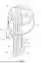
Refer to FIG. 1-6, a fixture of a top mounting faucet 1 according to the present invention is mounted on a countertop 2 for installation and fixing a faucet with water lines under the faucet. The fixture of a top mounting faucet 1 includes a base 10, a threaded rod 20, a moveable block 30, and a pressing hook 40.
The base 10 consists of a circular wall 11 abutting against the countertop 2, a bottom wall 12, and a mounting hole 13. The bottom wall 12 and the mounting hole 13 are located in the circular wall 11. The bottom wall 12 is provided with an insertion hole 121, a first stopping rod 122 extending downward from the bottom wall 12, and a pivoting lug 123 integrally formed at a rear end of the first stopping rod 122. The mounting hole 13 allows the water lines under the faucet to pass through.
The threaded rod 20 is pivotally connected to the insertion hole 121 and the pivoting lug 123 of the base 10 and rotatable.
The moveable block 30 is threaded to and rotatable on the threaded rod 20 and rotation of the moveable block 30 is limited by the first stopping rod 122. In this embodiment, the moveable block 30 is provided with a threaded hole 301 with which the threaded rod 20 is engaged.
The pressing hook 40 consists of a first curved portion 41, a second curved portion 42, and a connection portion 43 located between and connected with the first curved portion 41 and the second curved portion 42. The moveable block 30 is pivotally connected between a rear end of the first curved portion 41 and a position of first curved portion 41 opposite to the rear end. The first curved portion 41, the second curved portion 42, and the connection portion 43 are connected to form a mounting space 44 among them. The mounting space 44 is surrounded by the first curved portion 41, the second curved portion 42, and the connection portion 43. A notch 45 is formed between the rear end of the first curved portion 41 and a rear end of the second curved portion 42 and is communicating with the mounting space 44. The threaded rod 20 and the first stopping rod 122 can be inserted through the mounting space 44.
According to the above structural design, it is clearly shown in FIG. 2 and FIG. 3 that the moveable block 30 is pivotally connected to the pressing hook 40 at the position close to the first curved portion 41. An eccentric design together with the pivotal connection causes the pressing hook 40 on the removable block 30 to rotate or fall naturally at a tilt position due to self-weight of the pressing hook 40. Thus the pressing hook 40 can be passed through an installation hole 2a of the countertop 2, as shown in FIG. 6. As shown in FIG. 7, while rotating the threaded rod 20, the moveable block 30 is forced to drive the pressing hook 4 moving upward until the first curved portion 41 is contacting with and abutting against a bottom surface 2b of the countertop 2, as shown in FIG. 8. Keep rotating the threaded rod 20 and the pressing hook 4 is forced to turn from the tilt position to an installation position, as shown in FIG. 9. While being at the installation position, both the first curved portion 41 and the second curved portion 42 are pressed against the bottom surface 2b of the countertop 2 tightly at the same time. Thereby the base 10 is fixed above the countertop 2.
In this embodiment, the fixture of a top mounting faucet 1 further includes a limit end cap 50 which is fixed on a bottom of the threaded rod 20 under the pivoting lug 123 to limit upward movement of the threaded rod 20 and prevent the threaded rod 20 from coming off.
In this embodiment, as shown in FIG. 2 and FIG. 4, a leaning wall 124 is formed at one side of the first stopping rod 122 facing the moveable block 30. An against wall 31 is formed at one side of the moveable block 30 facing the first stopping rod 122. The against wall 31 is leaning against the leaning wall 124 and able to slide and move vertically along the leaning wall 124. It is understood that one side of the moveable block 30 is leaning against an inner wall surface of the rear end of the first curved portion 41 of the pressing hook 40 while the other side of the moveable block 30 is leaning against the leaning wall 124 of the first stopping rod 122. Thus the moveable block 30 is unable to rotate but only able to move vertically along the threaded rod 20 along with rotation of the threaded rod 20.
In this embodiment, the fixture of a top mounting faucet 1 further includes a rotating shaft 60. As shown in FIG. 2 and FIG. 4, the rotating shaft 60 is penetrating and pivotally connected to both the moveable block 30 and the pressing hook 40 so that the pressing hook 40 is able to be turned and switched between the tilt position and the installation position by rotation around the rotating shaft 60. For convenient assembly of the rotating shaft 60, the moveable block 30 is provided with a first shaft hole 32. A second shaft hole 411 is mounted to each of two opposite positions at the first curved portion 41 of the pressing hook 40. Thereby the rotating shaft 60 is inserted through and pivotally connected to the first shaft hole 32 and the second shaft holes 411.
In another feasible embodiment shown in FIG. 10 and FIG. 11, a pin 33 is directly projecting from one side of the moveable block 30 facing an inner side of the rear end of the first curved portion 41. The pin 33 is directly inserted in and pivotally connected to the second shaft holes 411 and the pivot connection can also be achieved.
As shown in FIG. 5, in this embodiment, a curved positioning wall 125 is extending downward from one side of the bottom wall 12 of the base 10 facing the first stopping rod 122 and able to abut against and position at an inner peripheral wall of the installation hole 2a of the countertop 2. The curved positioning wall 125 is designed to form a positioning reference point during installation and operation process in order to ensure that the mounting space 44 and the notch 45 of the pressing hook 40 can form sufficient installation region or area inside the installation hole 2a of the countertop 2 while at this position, as shown in FIG. 14. At the same time, the above design also ensures that the pressing hook 40 at the installation position can be tightly pressed against the bottom surface 2b around the installation hole 2a of the countertop 2 tightly with the better position or state. Thereby stability and quality of each installation and operation are ensured.
As shown in FIG. 3, in this embodiment, the fixture of a top mounting faucet 1 further includes a waterproof gasket 70. A bottom of the base 10 is provided with a pressing wall 14 formed around the curved positioning wall 125. As shown in FIG. 3, it is clear that the pressing wall 14 is arranged at a bottom of the circular wall 11 and the waterproof gasket 70 is tightly pressed between the pressing wall 14 and a top surface 2c around the installation hole 2a of the countertop 2. Thereby a better sealing and leak-resistant effect between the base 10 and the top surface 2c of the countertop 2 is ensured.
In this embodiment, the whole of or at least most part of the pressing hook 40 is tightly pressed against the bottom surface 2b around the installation hole 2a of the countertop 2. A diameter of the installation hole 2a is ranging from 25.4 mm to 38 mm. In other words, the present fixture of a top mounting faucet 1 can be mounted in the installation hole 2a with different sizes of general countertops.
In this embodiment, the pressing hook 40 at the tilt position is allowed to pass through the installation hole 2a with the diameter of at least 25.4 mm.
It should be noted that the diameter of the common installation hole 2a of the countertop 2 includes three sizes—38 mm, 32 mm, and 25.4 mm. Take the largest diameter 38 mm as an example. During installation and operation, users generally worry about that the fixture available now is unable to be locked on the bottom of the countertop smoothly. But it is ensured that the pressing hook 40 of the present fixture of a top mounting faucet 1 can be locked on the bottom surface 2b of the countertop 2 smoothly while being at the installation position.
Take the smallest diameter 25.4 mm as an example. During installation and operation, users generally worry about that the fixture available now is unable to be inserted through the installation hole 2a smoothly. As to the present top mounting faucet 1, it is ensured that the pressing hook 40 at the tilt position can be inserted through the installation hole 2a smoothly. Moreover, the water lines with different specifications and amount and under the faucet are allowed to be inserted through the installation hole 2a and the mounting space 44 and the notch 45 both in the installation hole 2a smoothly. After insertion and installation of the water lines, a main body or a housing of the faucet is mounted and fixed on the base 10 by various kinds of common ways. Thereby the faucet is fixed above the countertop 2 smoothly. The assembly of the main body or the housing of the faucet with the base 10 is quite common so that related details are not repeated here.
The above faucets can be in various forms. For example, the faucet can be either a kitchen faucet or a basin faucet, a single-handle faucet or a two-handle faucet, a pull-out faucet or a pull-down faucet. The pipeline can be a single water inlet pipe, two water inlet lines for cold and hot water, or four water lines for cold water, hot water, a pull-out tube, and mixed water. The present fixture of a top mounting faucet 1 can be applied to all types of faucets mentioned above. There is no need to prepare fixtures with different specifications so that installers or consumers can get and install the fixtures easily and conveniently.
As shown in FIG. 12 and FIG. 13, an outer surface of the first curved portion 41 of the pressing hook 40 is provided with a support projection 46. While the pressing hook 40 is at the tilt position, the support projection 46 is abutting against the bottom surface 2b around the installation hole 2a of the countertop 2 to form a longer lever arm and further ensure that the pressing hook 40 is able to turned to the installation position.
Refer to FIG. 3, in this embodiment, when the pressing hook 40 is at the tilt position, a tilt angle θ of the pressing hook 40 relative to the horizontal surface is ranging from 67 to 77 degrees. For example, the angle is about 72 degrees. This ensures a volume of a space formed by vertical movement of the pressing hook 40 passed through the installation hole 2a is smaller. Thus the pressing hook 40 can be smoothly passed through the installation hole 2a with the smallest diameter such as 25.4 mm.
As shown in FIG. 15, another embodiment of a fixture of a top mounting faucet 1 is provided. This embodiment is about the same as the above embodiment and a difference between this embodiment and the above one is in that this embodiment further includes a second stopping rod 126 which is disposed on a bottom of the bottom wall 12 of the base 10 and arranged in parallel to the first stopping rod 122. Two sides of the pivoting lug 123 are connected to the bottom of the first stopping rod 122 and a bottom of the second stopping rod 126 correspondingly. The moveable block 30 is limited to be moved between the first stopping rod 122 and the second stopping rod 126. Such design not only further limits rotation of the moveable block 30 but also improves structural strength of both the first stopping rod 122 and the second stopping rod 126. Thus the first stopping rod 122 and the second stopping rod 126 will not have deformation once improper force is applied to them and smooth movement of the moveable block 30 is further ensured.
As shown in FIG. 16, a third embodiment of a fixture of a top mounting faucet 1 is provided. This embodiment is similar to the second one mentioned above and a difference between them is in that this embodiment further includes a connection wall 127 and a limiting sliding groove 128.
The connection wall 127 is connected to the same sides of the first stopping rod 122 and the second stopping rod 126. The first stopping rod 122, the second stopping rod 126, and the connection wall 127 are connected to form a limiting sliding groove 128 among them. The limiting sliding groove 128 is surrounded by the first stopping rod 122, the second stopping rod 126, and the connection wall 127. The moveable block 30 is mounted in the limiting sliding groove 128 with limits on its rotation and able to be moved vertically along the limiting sliding groove 128.
A cross section of the first stopping rod 122, the second stopping rod 126, and the connection wall 127 connected with each other is about in a U-shape.
In this embodiment, the pivoting lug 123 is omitted and the limit end cap 50 is stopped by the first stopping rod 122, the second stopping rod 126, and a bottom of the connection wall 127. And upward movement of the threaded rod 20 is further limited and the threaded rod 20 will not come off.
As shown in FIG. 17, a fourth embodiment of a fixture of a top mounting faucet 1 is provided. This embodiment is similar to the second embodiment mentioned above. The difference between this embodiment and the above second one is only in that the first stopping rod 122 and the second stopping rod 126 of the base 10 are both cylindrical. Top ends of the first and the second stopping rods 122, 126 are inserted through and mounted to the bottom wall 12 while bottom ends of the first and the second stopping rods 122 are penetrating and slidably mounted to the moveable block 30. Such design can also limit rotation of the moveable block 30. The design not only helps production and assembly of the first stopping rod 122 and the second stopping rod 126 but also reduces molding difficulty and cost of parts.
Moreover, a limiting block 501 having function similar to that of the above limit end cap 50 in this embodiment. The limiting block 501 allows the bottom end of the first stopping rod 122 and the bottom end of the second stopping rod 126 to insert through and fix thereof and the bottom end of the threaded rod 20 is pivotally connected to the limiting block 501. The above design improves structural strength of the bottom of the first stopping rod 122 and the bottom of the second stopping rod 126. Thus the first stopping rod 122 and the second stopping rod 126 will not have deformation once improper force is applied to them and a gap with a certain length between them is ensured. Thereby smooth movement of the moveable block 30 is further ensured.
In summary, the pressing hook 40 has an open-style design. That means the mounting space 44 is communicating with the outside through the notch 45. A larger space is formed by the mounting space 44 combined with the notch 45, allowing water lines under the faucet with various sizes to insert through smoothly. Thus there is no need to increase the volume or width of the pressing hook 40. Moreover, the pressing hook 40 with smaller width or volume of the space formed by its vertical movement through the installation hole 2a can be passed through the installation hole 2a with different sizes on the countertop 2, especially the installation hole 2a with the smallest diameter such as 25.4 mm.
Furthermore, the open-style design allows the pressing hook 40 able to be shifted toward one side of the installation hole 2a of the countertop 2 during installation, as shown in FIG. 14. Thus the pressing hook 40 is shifted outward while being mounted in the installation hole 2a to form a larger installation space and ensure smooth insertion of the water lines under the faucet with quite a large volume. It is easily understood that the conventional closed loop design not only can't increase any space required, but also makes the space allowing the water lines to insert through become narrower when the looped pressing hook is shifted to one side of the installation hole of the countertop. The problem of insufficient installation space is getting worse.
At the tilt position, the pressing hook 40 can have a larger tilt angle relative to the horizontal surface. Thus the volume of the space formed by vertical movement of the tilted pressing hook 40 passed through the installation hole 2a is quite small. This ensures smooth movement of the pressing hook 40 through the installation hole 2a with the smaller diameter.
Additional advantages and modifications will readily occur to those skilled in the art. Therefore, the invention in its broader aspects is not limited to the specific details, and representative devices shown and described herein. Accordingly, various modifications may be made without departing from the spirit or scope of the general inventive concept as defined by the appended claims and their equivalent.
Claims
1. A fixture of a top mounting faucet comprising:
a base having a circular wall abutting against a countertop, and a bottom wall and a mounting hole both mounted in the circular wall; the bottom wall provided with an insertion hole and a first stopping rod arranged at a bottom of the bottom wall;
a threaded rod held by the insertion hole and a bottom of the first stopping rod of the base and rotatable;
a moveable block rotatably threaded to the threaded rod and rotation of the moveable block limited by the first stopping rod; and
a pressing hook having a first curved portion, a second curved portion, and a connection portion located between and connected with the first curved portion and the second curved portion; a rear end of the first curved portion pivotally connected to the moveable block so that the pressing hook is able to be turned and switched between an installation position and a tilt position at which the pressing hook is falling naturally; the first curved portion, the second curved portion, and the connection portion connected to one another form a mounting space among them; a notch formed between the rear end of the first curved portion and a rear end of the second curved portion and communicating with the mounting space; the first stopping rod and the threaded rod able to be inserted through the mounting space.
2. The fixture of a top mounting faucet as claimed in claim 1, wherein a pivoting lug is disposed on the bottom of the first stopping rod; the threaded rod is pivotally connected to the insertion bole and the pivoting lug of the base and rotatable.
3. The fixture of a top mounting faucet as claimed in claim 2, wherein the fixture of a top mounting faucet further includes a limit end cap which is fixed on a bottom of the threaded rod under the pivoting lug to limit upward movement of the threaded rod and prevent the threaded rod from coming off.
4. The fixture of a top mounting faucet as claimed in claim 1, wherein one side of the first stopping rod facing the moveable block is provided with a leaning wall while an against wall is formed at one side of the moveable block facing the first stopping rod; the against wall is leaning against the leaning wall and able to slide vertically along the leaning wall.
5. The fixture of a top mounting faucet as claimed in claim 1, wherein the fixture of a top mounting faucet further includes a rotating shaft which is penetrating and pivotally connected to both the moveable block and the pressing hook.
6. The fixture of a top mounting faucet as claimed in claim 1, wherein a curved positioning wall is extending downward from one side of the bottom wall of the base facing the first stopping rod and used for abutting against an inner peripheral wall of the installation hole of the countertop.
7. The fixture of a top mounting faucet as claimed in claim 6, wherein the fixture of a top mounting faucet further includes a waterproof gasket; the base is provided with a pressing wall formed around the curved positioning wall; the waterproof gasket is tightly pressed between the pressing wall and a top surface around the installation hole of the countertop.
8. The fixture of a top mounting faucet as claimed in claim 6, wherein the whole of or at least most part of the pressing hook is tightly pressed against a bottom surface around the installation hole of the countertop;
a diameter of the installation hole is ranging from 25.4 mm to 38 mm.
9. The fixture of a top mounting faucet as claimed in claim 8, wherein the pressing hook at the tilt position is allowed to pass through the installation hole with the diameter of at least 25.4 mm.
10. The fixture of a top mounting faucet as claimed in claim 1, wherein an outer surface of the first curved portion of the pressing hook is provided with a support projection; while the pressing hook is at the tilt position, the support projection is abutting against a bottom surface around the installation hole of the countertop.
11. The fixture of a top mounting faucet as claimed in claim 1, wherein a tilt angle of the pressing hook is ranging from 67 to 77 degrees when the pressing hook is at the tilt position.
12. The fixture of a top mounting faucet as claimed in claim 2, wherein a second stopping rod is disposed on the bottom of the bottom wall of the base and arranged in parallel to the first stopping rod; two sides of the pivoting lug are connected to the bottom of the first stopping rod and a bottom of the second stopping rod correspondingly; the moveable block is limited to be moved between the first stopping rod and the second stopping rod.
13. The fixture of a top mounting faucet as claimed in claim 1, wherein the bottom of the bottom wall of the base is provided with a second stopping rod arranged in parallel to the first stopping rod and a connection wall connected to the same sides of the first stopping rod and the second stopping rod; the first stopping rod, the second stopping rod, and the connection wall are connected to form a limiting sliding groove among them; the moveable block is mounted in the limiting sliding groove with limits on its rotation and able to be moved vertically along the limiting sliding groove.
14. The fixture of a top mounting faucet as claimed in claim 13, wherein the fixture of the top mounting faucet further includes a limit end cap fixed on a bottom of the threaded rod under the first stopping rod, the second stopping rod, and the connection wall to limit upward movement of the threaded rod and prevent the threaded rod from coming off.
15. The fixture of a top mounting faucet as claimed in claim 1, wherein the bottom of the bottom wall of the base is provided with a second stopping rod arranged in parallel to the first stopping rod, both the first stopping rod and the second stopping rod are penetrating and slidably mounted to the moveable block to limit rotation of the moveable block.
16. The fixture of a top mounting faucet as claimed in claim 15, wherein the fixture of a top mounting faucet further includes a limiting block; the limiting block allows the bottom of the first stopping rod and a bottom of the second stopping rod to insert through and fix thereof and a bottom of the threaded rod is pivotally connected to the limiting block.
Images & Drawings included:


Sources:
- United States Patent and Trademark Office - verify current appl. status at the USPTO↗
Recent applications in this class:
- » 20260062900 2026-03-05
FAUCET SUPPORT ASSEMBLY - » 20250369209 2025-12-04
Snap-fit quick installation device on faucet platform - » 20250243649 2025-07-31
PRE-EMBEDDED BASE DEVICE - » 20250101723 2025-03-27
BASIN FAUCET QUICK-MOUNTING BASE DEVICE - » 20250092649 2025-03-20
QUICK MOUNTING AND DISMOUNTING METHOD FOR FAUCET, AND QUICK-MOUNTING FAUCET - » 20250059737 2025-02-20
FAUCET - » 20240384512 2024-11-21
DUAL HANDLE CENTER MOUNTED FAUCET - » 20240384511 2024-11-21
ARRANGEMENT COMPRISING A SINK AND A TAP, AND COMPRISING A SPECIFIC CLAMPING DEVICE, AND METHOD - » 20240376697 2024-11-14
SYSTEMS AND METHODS FOR COUPLING OF A TUB SPOUT - » 20240309619 2024-09-19
MOUNTING ASSEMBLY FOR USE WITH A PLUMBING FIXTURE