PLATFORM SUPPORT RING AND METHOD OF USE
US20260062913A1
2026-03-05
19/309,705
2025-08-26
Smart Summary: A support ring is designed to make a modified grate stronger. It consists of two rings that are held together with fasteners, clamping part of the grate in between. The modified grate has a grid structure made of cross bars and bearing bars, with an opening for a construction member. This support ring fits around the opening to provide extra strength. It helps ensure the grate can handle weight and pressure around the area where the opening is located. 🚀 TL;DR
Abstract:
A support ring for strengthening a grate modified to form an aperture therein, wherein the support ring includes a first and a second ring. The first and second rings are secured to one another with one or more fasteners such that a portion of a modified grate is clamped between the first ring and the second ring. The support ring is installed on a modified grate. The modified grate includes a plurality of cross bars installed in or on a surface and a plurality of bearing bars installed in or one the surface which together form a grid. The modified gate includes an aperture bounded and defined by a portion of the plurality of the cross bars and a portion of the plurality of bearing bars to receive a construction member therethrough. The support ring operably engages with the grate adjacent the aperture.
Inventors:
- Michael Darwin Russo 4 🇺🇸 Minerva, OH, United States
- Ryan Christopher Hallgren 6 🇺🇸 Clinton, OH, United States
Assignee:
- OHIO GRATINGS, INC. 20 🇺🇸 Canton, OH, United States
Applicant:
Interested in similar patents?
Get notified when new applications in this technology area are published.
Classification:
E03F5/06 » CPC main
Sewerage structures; Gullies inlets, road sinks, floor drains with or without odour seals or sediment traps Gully gratings
Description
REFERENCE TO RELATED APPLICATIONS
This application claims the benefit of U.S. Provisional Application Ser. No. 63/689,092, filed on Aug. 30, 2024; the disclosure of which is incorporated herein by reference.
TECHNICAL FIELD
The present disclosure is directed to a grating with an aperture for an object such as a pipe to pass therethrough, where the grating is installed in a sidewalk or a road or is used for flooring or walkways. More specifically, the present disclosure relates to a platform support ring for use in a grating having an aperture formed therein, and to a grating incorporating the platform support ring. Specifically, the present disclosure is directed to a grate having a platform support ring installed therein during manufacture.
BACKGROUND ART
Gratings configured for supporting vehicle and/or pedestrian traffic are commonly used on sidewalks and road surfaces that require venting and/or drainage. Gratings are further commonly configured for use in overhead catwalks, platforms, flooring, walkways, trench covers and/or security enclosures. Typically, gratings are configured to permit variously sized wheel and/or foot traffic to pass thereover without catching or presenting a hazard thereto. Additionally, because gratings are installed in areas where they are seen and not easily concealed, they are typically designed to be both functional and aesthetically pleasing.
Gratings may be placed in locations that require an object, such as a pipe, to pass through the grating. During manufacture, an aperture may be cut or formed in the grate to provide a region for the object to pass therethrough. It is difficult to maintain the structural stability of the grating once the aperture is formed therein. Manufacturers will therefore commonly add additional support to the grating in the form of a collar which is welded to the grating so as to circumscribe the aperture formed therein. Other manufacturers will use a grating penetration collar or a toeboard link to support the grating. However, even with the additional support added during manufacture, it is not uncommon that a grating with an aperture formed therein will not have the same load capacity as the grating would have had before the aperture was formed therein.
SUMMARY OF THE INVENTION
In one aspect, an exemplary embodiment of the present disclosure may provide a support ring for strengthening a grate modified to form an aperture therein, wherein the support ring includes a first ring; a second ring; and a first set of connectors securing the first ring and the second ring to one another such that a portion of a modified grate is clamped between the first ring and the second ring.
In another aspect, an exemplary embodiment of the present disclosure may provide wherein the first ring includes a top surface; a bottom surface opposite to the top surface and being adapted to contact a top of the modified grate; and a ledge extending outwardly from the top surface and being adapted to protect a portion of a construction member. In another aspect, an exemplary embodiment of the present disclosure may provide wherein the first ring is formed from a first half and a second half. In another aspect, an exemplary embodiment of the present disclosure may provide further including a pair of tabs extending outwardly from the ledge. In another aspect, an exemplary embodiment of the present disclosure may provide wherein the first half and second half of the first ring are removably securable to one another at the pair of tabs. In another aspect, an exemplary embodiment of the present disclosure may provide further including a second set of connectors securing the first half and the second half of the first ring to one another. In another aspect, an exemplary embodiment of the present disclosure may provide wherein the second ring is formed from a first half and a second half.
In one aspect, an exemplary embodiment of the present disclosure may provide a modified grate including a plurality of cross bars installed in or on a surface; a plurality of bearing bars installed in or one the surface; wherein the plurality of cross bars and the plurality of bearing bars, together, form a grid; an aperture bounded and defined by a portion of the plurality of the cross bars and a portion of the plurality of bearing bars, said aperture being configured to receive a construction member therethrough; and a support ring operably engaged with the grate adjacent the aperture to provide structural support therein.
In another aspect, and exemplary embodiment of the present disclosure may provide wherein the support ring includes a first ring and a second ring; wherein the first ring and the second ring contact a top and a bottom of the grate; and one or more fasteners secure the first ring and the second ring to one another. In another aspect, and exemplary embodiment of the present disclosure may provide wherein an opening defines by the first ring and the second ring is in fluid communication with the aperture defined by the grate. In another aspect, and exemplary embodiment of the present disclosure may provide wherein the first ring and the second ring circumscribe the aperture. In another aspect, and exemplary embodiment of the present disclosure may provide wherein the first ring further includes a top surface; a bottom surface opposite to the top surface and being adapted to contact a top of the modified grate; and a ledge extending outwardly from a top surface and being adapted to protect a portion of a construction member.
In one aspect, an exemplary embodiment of the present disclosure may provide a method of modifying and strengthening a grate including determining a size and location of an aperture to be formed in the grate; modifying the grate by forming the aperture in the grate; providing a support ring comprising a first ring and a second ring; placing the first ring on a top surface of the grate so that the first ring circumscribes the aperture; placing the second ring on the bottom surface of the grate so that the second ring circumscribes the aperture; and securing the first ring and the second ring to one another.
In another aspect, and exemplary embodiment of the present disclosure may provide wherein the aperture extends from the top surface of the grate to the bottom surface thereof. In another aspect, and exemplary embodiment of the present disclosure may provide wherein the aperture is sized to receive a construction member therethrough. In another aspect, and exemplary embodiment of the present disclosure may provide wherein securing the first ring and the second ring further comprises clamping the portion of the grate surrounding the aperture between the first ring and the second ring. In another aspect, and exemplary embodiment of the present disclosure may provide further including securing a first half and a second half of the first ring to one another at a first set of tabs. In another aspect, and exemplary embodiment of the present disclosure may provide further including securing a first half and a second half of the second ring to one another at a second set of tabs. In another aspect, and exemplary embodiment of the present disclosure may provide further including extending a ledge upwardly from an upper surface of the first ring; and protecting a length of the construction member against impact with the ledge. In another aspect, and exemplary embodiment of the present disclosure may provide wherein clamping the portion of the grate including extending a pair of tabs from the ledge of each half of the first ring; and securing the respective halves of the first ring with one another, by one or more connectors, at the pair of tabs.
BRIEF DESCRIPTION OF THE DRAWINGS
Sample embodiments of the present disclosure are set forth in the following description, are shown in the drawings and are particularly and distinctly pointed out and set forth in the appended claims.
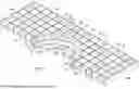
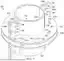
FIG. 1 is isometric view of a modified grate installed within a surface such as a sidewalk or road, wherein the modified grate defines an aperture therein and includes a first embodiment of a platform support ring in accordance with the present disclosure circumscribing the aperture.
FIG. 2 is an enlarged isometric view of the first embodiment of the platform support ring in accordance with the present disclosure shown in isolation.
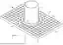
FIG. 3 is an enlarged isometric cross-section view taken along line 3-3 of FIG. 1 showing, in isolation, the modified grate including the first embodiment of the platform support ring.
FIG. 3A is a cross-section of the grate and the first embodiment of the platform support ring, in isolation, and taken along line 3-3 of FIG. 1.
FIG. 4 is an isometric view of the modified grate and the first embodiment of the platform support ring.
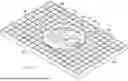
FIG. 5 is a isometric view of the modified grate including the first embodiment of the platform support ring which circumscribes the aperture and showing a construction member passing through the aperture.
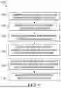
FIG. 6 is a flowchart depicting a method of installing and using the support ring on the grate.
FIG. 7 is an enlarged isometric view of a second embodiment of the platform support ring in accordance with the present disclosure shown in isolation.
FIG. 8 is an enlarged isometric view of the second embodiment of the platform support ring as shown in FIG. 7.
Similar numbers refer to similar parts throughout the drawings.
DETAILED DESCRIPTION
FIG. 1 shows a sidewalk (or road) “S” into which a modified grate 10 has been installed. The modified grate 10 may also be referred to herein as a “grate”, an “installed grate”, a “grating” or a “grating assembly”. Grate 10 comprises a grate frame 12, a plurality of cross bars 14, and a plurality of bearing bars 16.
Referring now to FIG. 3A, modified grate 10 includes a top 10A and a bottom 10B opposite and spaced apart from one another. Modified grate 10 further includes a first end 10C and a second end 10D opposite and spaced apart from one another. Modified grate 10 defines an imaginary horizontal axis “X” extending between top 10A and bottom 10B and an imaginary vertical axis “Y” extending between first end 10C and second end 10D.
Grate frame 12 includes a first frame member 12A, a second frame member 12B, a third frame member 12C, and a fourth frame member 12D. First frame member 12A and second frame member 12B are opposed to one another, spaced a distance apart from one another, and are arranged parallel to one another. Third frame member 12C and fourth frame member 12D are opposed to one another, spaced a distance apart from one another, and are arranged parallel to one another. Each of the first frame member 12A, second frame member 12B, third frame member 12C, and fourth frame member 12D comprises a rolled metal component which is welded or otherwise secured at each end to an end of an adjacent frame member in order to form an integral grate frame.
The configuration of each frame member 12A, 12B, 12C, 12D, may vary depending on the particular application and location of grate 10. It will be understood that the overall height of the first frame member 12A, second frame member 12B, third frame member 12C, and fourth frame 12D will vary based on the desired overall size of grate 10. In the embodiment illustrated in FIG. 1, first frame member 12A, second frame member 12B, third frame member 12C, and fourth frame member 12D will be of the same height as one another.
Cross bars 14 extend between first frame member 12A and second frame member 12B and bearing bars 16 extend between third frame member 12C and fourth frame member 12D. Ends of cross bars 14 may be secured to first frame member 12A and second frame member 12B while ends of bearing bars 16 may be secured to third frame member 12C and fourth frame member 12D. Ends of cross bars and bearing bars 14, 16 may be welded to the respective first, second, third, and fourth frame member 12A, 12B, 12C, and 12D. It will be understood that cross bars 14 and bearing bars 16 may alternatively extend between and be secured or welded to any of the first, second, third and fourth frame members 12A, 12B, 12C, and 12D.
It will be understood that grate 10 may include any number of cross bars 14 and bearing bars 16. It will be understood that each cross bar 14 of the plurality of cross bars 14 is substantially identical in structure and function. Similarly, each bearing bar 16 of the plurality of bearing bar 16 is substantially identical in structure and function.
The plurality of cross bars 14 and the plurality of bearing bars 16 are configured to intersect one another to form a grid. The cross bars 14 and bearing bars 16, together, bound and define a plurality of small openings 15 through which air and water may flow from above the grate 10 to below the grate 10.
It will be understood that grate frame 12 of grate 10 may alternatively be outer grate bearing bars or end bands and a grate frame or a structural support may be external to grate 10.
Grate 10 as illustrated in FIG. 1 is generally rectangular in shape, but it will be understood that, in other embodiments, grate 10 may alternatively be square or of any other desired shape.
The frame 12 of grate 10 is illustrated as being permanently installed into sidewalk or road “S” via a compound material “CM”. The compound material “CM” may be any suitable material used to construct sidewalk or road “S”. Suitable materials for use as the compound material “CM” include, but are not limited to, concrete and asphalt. It should be understood that any other compound material which dries and hardens, may be used instead of concrete or asphalt. The compound material “CM” may be any material that can achieve the strength necessary for pedestrians and/or vehicles to move across the installed grate 10. Additionally, while grate 10 depicted herein is illustrated as installed within sidewalk or road “S”, the grate 10 may be utilized in any application where there is a need for a grating to be permanently installed within a compound material “CM”.
It will be understood that modified grate 10 may, alternatively, be utilized for overhead catwalks, platforms, flooring, walkway, trench cover and/or security enclosures and are secured in alternative ways other than by using a compound material “CM”. In these applications, the grating 10 may be welded or otherwise secured to a supporting structure such as metal scaffolding which includes support posts and support beams.
Referring still to FIG. 1, grate 10 defines an aperture 18 which is cut or otherwise formed in the grid of intersecting cross bars 14 and bearing bars 16. Aperture 18 is located and sized so as to be able to receive at least a portion of a construction member “C” therethrough. The construction member “C” may, for example, be a pipe or a conduit. When the construction member “C” is received through the aperture, the construction member is oriented orthogonally to an upper surface of the grate 10. The grate 10 with the aperture 18 formed therein may also be referred to herein as “modified grate” 10.
In accordance with an aspect of the present disclosure, a first embodiment of a support ring 20 is provided for engagement with the modified grate 10. The support ring 20 is configured to be placed on grate 10 in such a manner as to provide structural strength and support to that part of the modified grate 10 into which the aperture 18 has been cut or formed. In accordance with an aspect of the present disclosure, support ring 20 comprises a first ring 22 and a second ring 24 which are arranged adjacent opposite surfaces of the grate 10. The first ring 22 and second ring 24 are arranged substantially parallel to one another and parallel to an upper surface and a lower surface of the grate 10. As will be discussed later herein, portions of the grate 10 surrounding the aperture 18 are clamped or clampingly engaged between the first ring 22 and second ring 24.
Referring now to FIGS. 2-3A, first ring 22 is an annular ring having a top surface 22A and a bottom surface 22B opposite one another and defining the upper and lower limits of first ring 22. As best seen in FIG. 3A, the bottom surface 22B of first ring 22 is planar, i.e., flat. First ring 22 further includes a circumferential inner edge 22C and a circumferential outer edge 22D opposite one another. Inner edge 22C bounds and defines an opening 22E which extends from the top surface 22A to the bottom surface 22B of first ring 22. The distance of first ring 22 between inner edge 22C and outer edge 22D may vary based on the specific application in which support ring 20 is utilized.
First ring 22 further includes a ledge 26 which extends outwardly from top surface 22A of first ring 22. Ledge 26 is oriented generally at ninety degrees to top surface 22A. As illustrated in FIGS. 1-3A, a portion of the inner edge 22C extends upwardly beyond top surface 22A to form part of the ledge 26. When support ring 22 is installed on grate 10 and construction member “C” is extended through aperture 18, ledge 26 will form a toe kick or toe guard around the construction member “C”.
Referring now to FIGS. 1-3A, first ring 22 defines at least one hole 28 extending from the top surface 22A through to the bottom surface 22B thereof. Hole 28 is configured to receive a portion of a fastener 30, also referred to herein as first set of fasteners 30 or first set of connectors 30, therethrough. It will be understood that first ring 22 may include any number of holes 28 and therefore be engaged with any number of respective connectors or fasteners 30.
First ring 22 is illustrated in the attached figures as being generally circular in shape and defining a generally circular opening 22E therein so as to be generally complementary to aperture 18 in grate 10. It will be understood, however, that in other embodiments, first ring 22 may be square in shape or of any other desired shape and that the opening 22E defined therein will be complementary in shape to the aperture 18 defined in grid 10. It will further be understood that the size of opening 22E defined in first ring 22 will be complementary to the size of aperture 18 defined in grid 10.
It will further be understood that first ring 22 as illustrated herein is formed as one singular piece, but in other embodiments, first ring 22 may, alternatively, be formed in sections such as a first half and a second half or any number of pieces operatively engaged with one another.
Referring now to FIGS. 2-4, second ring 24 of support ring 20 is an annular ring having a top surface 24A and a bottom surface 24B opposite one another and defining the upper and lower limits of second ring 24. As best seen in FIG. 3A, top surface 24A of second ring 24 is substantially planar, i.e., flat. Second ring 24 further includes a circumferential inner edge 24C and a circumferential outer edge 24D opposite one another. Inner edge 24C bounds and defines an opening 24E which extends from top surface 24A through to bottom surface 24B of second ring 24. The distance of second ring 24 between inner edge 24C and outer edge 24D may vary based on the specific application in which support ring 20 is utilized. Opening 24E defined by second ring 24 is substantially complementary in shape and size to opening 22E defined in first ring 22 and to aperture 18 defined in grate 10. Second ring 24 differs from first ring 22 in that second ring 24 does not include a ledge similar to ledge 26 on first ring 22.
Second ring 24 defines at least one bore 32 extending from the top surface 24A through bottom surface 24B. Each bore 32 is configured to receive a portion of fastener 30 therein. It will be understood that the number and location of holes 28 of first ring 22 and bores 32 of second ring 24 is substantially complementary and that each bore 32 is located so as to be alignable with a respective hole 28 when first ring 22 and second ring 24 are installed on grate 10. Fasteners 30 will extend through the aligned holes 28 and bores 32 and will secure first ring 22 and second ring 24 to one another.
It will be understood that second ring 24 is illustrated as being generally circular in shape but it will be understood that in other embodiments, second ring 24 may be square or of any other desired shape to be suitable for engagement with grate 10. As indicated earlier herein, opening 24E defined in second ring 24 will be complementary to aperture 18 and opening 22E in first ring 22. Opening 24E may therefore be circular or square or another different shape as is necessary to allow for the construction member “C” to pass through aperture 18.
It will further be understood that while second ring 24 is illustrated as being formed as a singular piece, in other embodiments, second ring may, alternatively, be formed as two separate pieces or may be formed as any other number of pieces which are operatively engaged with one another.
Referring now to FIGS. 1-3A, support ring 20 is engaged with grate 10 as described hereafter. First ring 22 is operatively engageable with grate 10 by placing bottom surface 22B of first ring 22 in direct contact with an upper surface or the top 10A of grate 10. In other words, bottom surface 22B of first ring 22 is placed in direct contact with the upper ends 14A of cross bars 14 and the upper ends 16A of bearing bars 16 which bound and define aperture 18. As illustrated in FIG. 3A, when first ring 22 is positioned in contact with the upper surface of grate 10, the bottom surface 22B of first ring 22 is substantially parallel to the upper ends 14A, 16A of cross bars 14 and bearing bars 16 circumscribing aperture 18.
Referring now to FIGS. 3-4, second ring 24 is operatively engageable with grate 10 by placing top surface 24A of second ring 24 in direct contact with the bottom ends 14B of cross bars 14 and the bottom ends 16B of bearing bars 16 which bound and define aperture 18. As illustrated in FIG. 3A, once second ring 24 is placed in contact with the lower surface or the bottom 10B of grate 10, top surface 24A of second ring 24 is substantially parallel to bottom ends 14B, 16B of cross bars 14 and bearing bars 16. The top surface 24A of second ring 24 is also parallel to bottom surface 22b of first ring 22.
When first ring 22 is placed in abutting contact with top ends 14A, 16A of cross bars 14 and bearing bars 16 and second ring 24 is placed in abutting contact with bottom ends 14B, 16B of cross bars 14 and bearing bars 16, the rings 22, 24 are rotated relative to one another in order to bring the holes 18 and bores 32 into vertical alignment with one another. Fasteners 30 are then inserted through the aligned holes 18 and bores 32 and thereby extend between top surface 22A of first ring 22 and bottom surface 24B of second ring 24. A nut 34 is engaged with each fastener 30 to secure first ring 22 and second ring 24 to one another and to thereby clamp a portion of grate 10 surrounding aperture 18 therebetween. Support ring 20, when clampingly engaging the portion of grate 10 therebetween, reinforces the aperture 18 and provides improved structural strength and stability to the modified grate 10. FIG. 5 shows the modified grate 10 with a construction member “C” passing through the aperture 18 which has been reinforced with the support ring 20. Opening 22E is in fluid communication with aperture 18 when support ring 20 is installed on modified grate 10. Opening 24E is in fluid communication with aperture 18 when support ring 20 is installed on modified grate 10.
Having now described the structural features of grate 10 and support ring 20, a method 100 of installing and using support ring 20 on grate 10 will be described in greater detail (see FIG. 6). A purchaser will order a grate 10 with the specifications that at least a portion of the grate 10 will need to be removed in order to allow for a construction member “C” to pass through the grate 10.
A first step 102 includes a worker determining the location and size of the aperture 18 needed in grate 10 to allow construction member “C” to pass therethrough. The worker will determine the location and size of aperture 18 from the specification sent by the purchaser or by any other appropriate means. A second step 104 includes modifying the grate 10 by forming the aperture 18 in the grate 10. Specifically, the grate 10 is modified by cutting the cross bars 14 and bearing bars 16 to form the required aperture 18.
Another step 106 includes providing a support ring 20 having the first ring 22 and the second ring 22. The first ring 22 and the second ring 24 are generally complementary to one another and to aperture 18. In one specific embodiment, the support ring 20 is purchased from a manufacturer. In another specific embodiment, the worker fabricates the support ring 20.
Another step 108 includes placing the first ring 22 on a top surface 10B of the grate 10 so that the first ring 22 circumscribes the aperture 18. Specifically, the worker places first ring 22 in physical contact with upper ends 14A, 16A of cross bars 14 and bearing bars 16 surrounding aperture 18 and so that the opening 22E defined by inner edge 22C aligns with aperture 18. Another step 110 includes placing the second ring 24 on a bottom surface 10B of the grate 10 so that the second ring 24 circumscribes the aperture 18. Specifically, the worker places second ring 24 in physical contact with bottom ends 14B, 16B of cross bars 14 and bearing bars 16 and so that the opening 24E defined by inner edge 24C aligns with aperture 18 and with the opening 22E.
Another step 112 includes securing the first ring 22 and the second ring 24 to one another. This step 112 may further include that once first ring 22 and second ring 24 are in position on grate 10, worker rotates one or both of first ring 22 and second ring 24 to bring holes 28 in first ring 22 and bores 32 in second ring 24 into vertical alignment with one another. The worker then inserts fasteners 30 through the aligned holes 28 and bores 32. The head of each fastener 30 will rest upon top surface 22A of first ring 22, and the worker will thread a nut 34 onto the shaft of the fastener 30 and will rotate the same until the nut 34 contacts the bottom surface 24B of second ring 24. When nut 34 is tightened to secure fasteners 30 in place, first ring 22 and second ring 24 are clampingly secured to grate 10 and thereby provide increased structural strength and support to grate 10 in the immediate vicinity of the aperture 18 formed therein.
The method 100 may further include that the aperture 18 extends from the top surface 10A to the bottom surface 10B of the grate 10. The method 100 may also include that the aperture 18 is sized to receive the construction member “C” therethrough. The method 100 may further include that securing the first ring 22 and the second ring 24 includes clamping the portion of the grate 10 surrounding the aperture 18 between the first ring 22 and the second ring 24.
The method 100 may further include an additional or optional step of extending the ledge 26 upwardly from the upper surface 22A of the first ring 22. The method 100 may further include an additional or optional step of protecting a length of the construction member “C” against impact with the ledge 26.
The method 100 may further include an additional or optional step of inserting one or more fasteners 30 into one or more holes 28 defined in each of the first ring 22 and the second ring 24 and tightening the one or more fasteners 30 to clamp the portion of the grate 10.
Referring now to FIGS. 7 and 8, in accordance with another aspect of the present disclosure, a second embodiment of a support ring 220 is provided for engagement with the modified grate 10. Support ring 220 is substantially identical in function to support ring 20, and the support ring 220 is configured to be placed on grate 10 in such a manner as to provide structural strength and support to that part of the modified grate 10 into which the aperture 18 has been cut or formed. In accordance with an aspect of the present disclosure, support ring 220 comprises a first ring 222 and a second ring 224 which are arranged adjacent opposite surfaces of the grate 10. The first ring 222 and second ring 224 are arranged substantially parallel to one another and parallel to an upper surface and a lower surface of the grate 10. Support ring 220 is substantially identical in function to support ring 20, as such, portions of the grate 10 surrounding the aperture 18 are clampingly engaged between the first ring 222 and second ring 224.
First ring 222 and second ring 224 are substantially identical to one another and are mirror images of one another along the imaginary horizontal axis “X” (FIG. 3A) of modified grate 10. Therefore, the following description of first ring 222 will be understood to apply equally to second ring 224.
First ring 222 includes a first half 222′ and a second half 222″. It will be understood that first half 222′ and second half 222″ are substantially identical to one another and mirror image of one another along the imaginary vertical axis “Y” (FIG. 3A) of the modified grate. Therefore, the following description of first half 222′ will be understood to apply equally to second half 222″.
First half 222′ includes a top surface 222A and a bottom surface 222B opposite one another and defining the upper and lower limits of first half 222′. The bottom surface 222B of first half 222′ is planar, i.e., flat. First half 222′ further includes a circumferential inner edge 222C and a circumferential outer edge 222D opposite one another. Inner edge 222C bounds and defines an opening 222E which extends from the top surface 222A to the bottom surface 222B of first half 222′. The distance of first half 222′ between inner edge 222C and outer edge 222D may vary based on the specific application in which support ring 220 is utilized.
First half 222′ further includes a ledge 226 which extends outwardly from top surface 222A of first half 222′. Ledge 226 is oriented generally at ninety degrees to top surface 222A. A portion of the inner edge 222C extends upwardly beyond top surface 222A to form part of the ledge 226. When support ring 222 is installed on grate 10 and construction member “C” is extended through aperture 18, ledge 226 will form a toe kick or toe guard around the construction member “C”.
Ledge 226 includes a first end 226A and a second end 226B defining the ends of the ledge 226. It will be understood that first end 226A and second end 226B are spaced apart from one another such that ledge 226 circumvents approximately half the distance of first ring 222.
Referring now to FIG. 1-3A, first half 222′ defines at least one hole or slot 228 extending from the top surface 222A through to the bottom surface 222B thereof. Hole 228 is configured to receive a portion of a fastener 230, also referring to herein as first set of fasteners 230 or first set of connectors 230, therethrough for securing the first half 222′ of first ring 222 with an opposing first half of the second ring 224. It will be understood that first half 222′ may include any number of holes 228 and therefore be engaged with any number of respective connectors or fasteners 230 for securing the first half 222′ of first ring 222 with an opposing first half of the second ring 224.
First half 222′ further includes a pair of tabs 234A,234B extending outwardly from ledge 226. It will be understood that the pair of tabs 234A,234B extending outwardly from ledge 226 at first end 226A and second end 226B respectively.
Each of the pair of tabs 234 defines at least one hole 236 extending through each of the pair of tabs 224. Hole 236 is configured to receive a portion of a fastener 238, also referred to herein as second set of fasteners 238 or second set of connectors 238, therethrough for securing the first half 222′ of first ring 222 with the opposing second half 222″ of the first ring 222. It will be understood that each of the pair of tabs 234 may include any number of holes 236 and therefore be engaged with any number of respective connectors or fasteners 238 for securing the first half 222′ of first ring 222 with the opposing second half 222″ of the first ring 222.
As best seen in FIG. 7, fasteners 238 are configured to secure first half 222′ and 222″ of first ring 222 to one another to form first ring 222 in its entirety.
Both first half 222′ and second half 222″ of first ring 222 are illustrated in the attached figures as being generally circular in shape and defining a generally circular opening (opening 222E of each the first half 222′ and second half 222″ together) therein so as to be generally complementary to aperture 18 in grate 10. It will be understood, however, that in other embodiments, first ring 222 may be square in shape or of any other desired shape and that the opening defined therein will be complementary in shape to the aperture 18 defined in grid 10. It will further be understood that the size of opening defined in first ring 222 will be complementary to the size of aperture 18 defined in grid 10.
It will further be understood that first ring 222 as illustrated herein is formed as a first half and a second half, but in other embodiments, first ring 222 may, alternatively, be formed in any number of pieces operatively engaged with one another.
It will be understood that support ring 220 may be engaged with grate 10 in an identical fashion as support ring 20, described above, expect for difference outlined hereafter.
It will be understood that before or after first ring 222 is operably engaged with the upper surface of grate 10, the first half 222′ and the second half 222″ are removably secured to one another. Specifically, the first half 222′ and the second half 222″ are removably secured to one another by threading and tightening fastener 238 through the at least one hole 236 on each the first half 222′ and the second half 222″ thereby securing first half 222′ and second half 222″ to one another.
It will also be understood that before or after second ring 224 is operably engaged with the bottom surface of grate 10, the first half and second half of second ring 224 are removably secured to one another identical to first half 222′ and second half 222″ of first ring 222.
Unless explicitly stated that a particular shape or configuration of a component is mandatory, any of the elements, components, or structures discussed herein may take the form of any shape. Thus, although the figures depict the various elements, components, or structures of the present disclosure according to one or more exemplary embodiments, it is to be understood that any other geometric configuration of that element, component, or structure is entirely possible. For example, instead of the first and second rings being circular, the first and second rings 22 and 24 can be semi-circular triangular, rectangular or square, pentagonal, hexagonal, heptagonal, octagonal, decagonal, dodecagonal, diamond shaped or another parallelogram, or trapezoidal.
Various inventive concepts may be embodied as one or more methods, of which an example has been provided. The acts performed as part of the method may be ordered in any suitable way. Accordingly, embodiments may be constructed in which acts are performed in an order different than illustrated, which may include performing some acts simultaneously, even though shown as sequential acts in illustrative embodiments.
While various inventive embodiments have been described and illustrated herein, those of ordinary skill in the art will readily envision a variety of other means and/or structures for performing the function and/or obtaining the results and/or one or more of the advantages described herein, and each of such variations and/or modifications is deemed to be within the scope of the inventive embodiments described herein. More generally, those skilled in the art will readily appreciate that all parameters, dimensions, materials, and configurations described herein are meant to be exemplary and that the actual parameters, dimensions, materials, and/or configurations will depend upon the specific application or applications for which the inventive teachings is/are used. Those skilled in the art will recognize or be able to ascertain using no more than routine experimentation, many equivalents to the specific inventive embodiments described herein. It is, therefore, to be understood that the foregoing embodiments are presented by way of example only and that, within the scope of the appended claims and equivalents thereto, inventive embodiments may be practiced otherwise than as specifically described and claimed. Inventive embodiments of the present disclosure are directed to each individual feature, system, article, material, kit, and/or method described herein. In addition, any combination of two or more such features, systems, articles, materials, kits, and/or methods, if such features, systems, articles, materials, kits, and/or methods are not mutually inconsistent, is included within the inventive scope of the present disclosure.
All definitions, as defined and used herein, should be understood to control over dictionary definitions, definitions in documents incorporated by reference, and/or ordinary meanings of the defined terms.
The articles “a” and “an,” as used herein in the specification and in the claims, unless clearly indicated to the contrary, should be understood to mean “at least one.” The phrase “and/or,” as used herein in the specification and in the claims (if at all), should be understood to mean “either or both” of the elements so conjoined, i.e., elements that are conjunctively present in some cases and disjunctively present in other cases. Multiple elements listed with “and/or” should be construed in the same fashion, i.e., “one or more” of the elements so conjoined. Other elements may optionally be present other than the elements specifically identified by the “and/or” clause, whether related or unrelated to those elements specifically identified. Thus, as a non-limiting example, a reference to “A and/or B”, when used in conjunction with open-ended language such as “comprising” can refer, in one embodiment, to A only (optionally including elements other than B); in another embodiment, to B only (optionally including elements other than A); in yet another embodiment, to both A and B (optionally including other elements); etc. As used herein in the specification and in the claims, “or” should be understood to have the same meaning as “and/or” as defined above. For example, when separating items in a list, “or” or “and/or” shall be interpreted as being inclusive, i.e., the inclusion of at least one, but also including more than one of a number or list of elements, and, optionally, additional unlisted items. Only terms clearly indicated to the contrary, such as “only one of” or “exactly one of,” or, when used in the claims, “consisting of,” will refer to the inclusion of exactly one element of a number or list of elements. In general, the term “or” as used herein shall only be interpreted as indicating exclusive alternatives (i.e. “one or the other but not both”) when preceded by terms of exclusivity, such as “either,” “one of,” “only one of,” or “exactly one of.” “Consisting essentially of,” when used in the claims, shall have its ordinary meaning as used in the field of patent law.
As used herein in the specification and in the claims, the phrase “at least one,” in reference to a list of one or more elements, should be understood to mean at least one element selected from any one or more of the elements in the list of elements, but not necessarily including at least one of each and every element specifically listed within the list of elements and not excluding any combinations of elements in the list of elements. This definition also allows that elements may optionally be present other than the elements specifically identified within the list of elements to which the phrase “at least one” refers, whether related or unrelated to those elements specifically identified. Thus, as a non-limiting example, “at least one of A and B” (or, equivalently, “at least one of A or B,” or, equivalently “at least one of A and/or B”) can refer, in one embodiment, to at least one, optionally including more than one, A, with no B present (and optionally including elements other than B); in another embodiment, to at least one, optionally including more than one, B, with no A present (and optionally including elements other than A); in yet another embodiment, to at least one, optionally including more than one, A, and at least one, optionally including more than one, B (and optionally including other elements); etc.
While components of the present disclosure are described herein in relation to each other, it is possible for one of the components disclosed herein to include inventive subject matter, if claimed alone or used alone. In keeping with the above example, if the disclosed embodiments teach the features of A and B, then there may be inventive subject matter in the combination of A and B, A alone, or B alone, unless otherwise stated herein.
As used herein in the specification and in the claims, the term “effecting” or a phrase or claim element beginning with the term “effecting” should be understood to mean to cause something to happen or to bring something about. For example, effecting an event to occur may be caused by actions of a first party even though a second party actually performed the event or had the event occur to the second party. Stated otherwise, effecting refers to one party giving another party the tools, objects, or resources to cause an event to occur. Thus, in this example a claim element of “effecting an event to occur” would mean that a first party is giving a second party the tools or resources needed for the second party to perform the event, however the affirmative single action is the responsibility of the first party to provide the tools or resources to cause said event to occur.
When a feature or element is herein referred to as being “on” another feature or element, it can be directly on the other feature or element or intervening features and/or elements may also be present. In contrast, when a feature or element is referred to as being “directly on” another feature or element, there are no intervening features or elements present. It will also be understood that, when a feature or element is referred to as being “connected”, “attached” or “coupled” to another feature or element, it can be directly connected, attached or coupled to the other feature or element or intervening features or elements may be present. In contrast, when a feature or element is referred to as being “directly connected”, “directly attached” or “directly coupled” to another feature or element, there are no intervening features or elements present. Although described or shown with respect to one embodiment, the features and elements so described or shown can apply to other embodiments. It will also be appreciated by those of skill in the art that references to a structure or feature that is disposed “adjacent” another feature may have portions that overlap or underlie the adjacent feature.
Spatially relative terms, such as “under”, “below”, “lower”, “over”, “upper”, “above”, “behind”, “in front of”, and the like, may be used herein for ease of description to describe one element or feature's relationship to another element(s) or feature(s) as illustrated in the figures. It will be understood that the spatially relative terms are intended to encompass different orientations of the device in use or operation in addition to the orientation depicted in the figures. For example, if a device in the figures is inverted, elements described as “under” or “beneath” other elements or features would then be oriented “over” the other elements or features. Thus, the exemplary term “under” can encompass both an orientation of over and under. The device may be otherwise oriented (rotated 90 degrees or at other orientations) and the spatially relative descriptors used herein interpreted accordingly. Similarly, the terms “upwardly”, “downwardly”, “vertical”, “horizontal”, “lateral”, “transverse”, “longitudinal”, and the like are used herein for the purpose of explanation only unless specifically indicated otherwise.
Although the terms “first” and “second” may be used herein to describe various features/elements, these features/elements should not be limited by these terms, unless the context indicates otherwise. These terms may be used to distinguish one feature/element from another feature/element. Thus, a first feature/element discussed herein could be termed a second feature/element, and similarly, a second feature/element discussed herein could be termed a first feature/element without departing from the teachings of the present disclosure.
An embodiment is an implementation or example of the present disclosure. Reference in the specification to “an embodiment,” “one embodiment,” “some embodiments,” “one particular embodiment,” “an exemplary embodiment,” or “other embodiments,” or the like, means that a particular feature, structure, or characteristic described in connection with the embodiments is included in at least some embodiments, but not necessarily all embodiments, of the invention. The various appearances “an embodiment,” “one embodiment,” “some embodiments,” “one particular embodiment,” “an exemplary embodiment,” or “other embodiments,” or the like, are not necessarily all referring to the same embodiments. Furthermore, the use of any and all examples or exemplary language (“e.g.,” “such as,” or the like) is intended merely to better illustrate or illuminate the embodiments and does not pose a limitation on the scope of that or those embodiments. No language in this specification should be construed as indicating any unclaimed element as essential to the practice of the disclosed embodiment.
If this specification states a component, feature, structure, or characteristic “may”, “might”, or “could” be included, that particular component, feature, structure, or characteristic is not required to be included. If the specification or claim refers to “a” or “an” element, that does not mean there is only one of the element. If the specification or claims refer to “an additional” element or “another” element, that does not preclude there being more than one of the additional element or the another element.
Additionally, the method of performing the present disclosure may occur in a sequence different than those described herein. Accordingly, no sequence of the method should be read as a limitation unless explicitly stated. It is recognizable that performing some of the steps of the method in a different order could achieve a similar result.
In the claims, as well as in the specification above, all transitional phrases such as “comprising,” “including,” “carrying,” “having,” “containing,” “involving,” “holding,” “composed of,” and the like are to be understood to be open-ended, i.e., to mean including but not limited to. Only the transitional phrases “consisting of” and “consisting essentially of” shall be closed or semi-closed transitional phrases, respectively.
To the extent that the present disclosure has utilized the term “invention” in various titles or sections of this specification, or in the context of those sections, this term has been included as required by the formatting requirements of word document submissions (i.e., docx submissions) pursuant the guidelines/requirements of the United States Patent and Trademark Office and shall not, in any manner, be considered a disavowal of any subject matter.
In the foregoing description, certain terms have been used for brevity, clearness, and understanding. No unnecessary limitations are to be implied therefrom beyond the requirement of the prior art because such terms are used for descriptive purposes and are intended to be broadly construed.
Moreover, the description and illustration of various embodiments of the disclosure are examples and the disclosure is not limited to the exact details shown or described.
Claims
What is claimed is:1. A support ring for strengthening a grate modified to form an aperture therein, wherein the support ring comprises:
a first ring;
a second ring; and
a first set of connectors securing the first ring and the second ring to one another such that a portion of a modified grate is clamped between the first ring and the second ring.
2. The support ring according to claim 1, wherein the first ring comprises:
a top surface;
a bottom surface opposite to the top surface and being adapted to contact a top of the modified grate; and
a ledge extending outwardly from the top surface and being adapted to protect a portion of a construction member.
3. The support ring according to claim 2, wherein the first ring is formed from a first half and a second half.
4. The support ring according to claim 3, further comprising:
a pair of tabs extending outwardly from the ledge.
5. The support ring according to claim 4, wherein the first half and second half of the first ring are removably securable to one another at the pair of tabs.
6. The support ring according to claim 3, further comprising:
a second set of connectors securing the first half and the second half of the first ring to one another.
7. The support ring according to claim 4, wherein the second ring is formed from a first half and a second half.
8. A modified grate comprising:
a plurality of cross bars installed in or on a surface;
a plurality of bearing bars installed in or one the surface;
wherein the plurality of cross bars and the plurality of bearing bars, together, form a grid;
an aperture bounded and defined by a portion of the plurality of the cross bars and a portion of the plurality of bearing bars, said aperture being configured to receive a construction member therethrough; and
a support ring operably engaged with the grate adjacent the aperture to provide structural support therein.
9. The modified grate according to claim 8, wherein the support ring comprises:
a first ring and a second ring;
wherein the first ring and the second ring contact a top and a bottom of the grate; and
one or more fasteners secure the first ring and the second ring to one another.
10. The modified grate according to claim 9, wherein an opening defines by the first ring and the second ring is in fluid communication with the aperture defined by the grate.
11. The modified grate according to claim 9, wherein the first ring and the second ring circumscribe the aperture.
12. The modified grate according to claim 9, wherein the first ring further comprises:
a top surface;
a bottom surface opposite to the top surface and being adapted to contact a top of the modified grate; and
a ledge extending outwardly from a top surface and being adapted to protect a portion of a construction member.
13. A method of modifying and strengthening a grate comprising:
determining a size and location of an aperture to be formed in the grate;
modifying the grate by forming the aperture in the grate;
providing a support ring comprising a first ring and a second ring;
placing the first ring on a top surface of the grate so that the first ring circumscribes the aperture;
placing the second ring on the bottom surface of the grate so that the second ring circumscribes the aperture; and
securing the first ring and the second ring to one another.
14. The method according to claim 13, wherein the aperture extends from the top surface of the grate to the bottom surface thereof.
15. The method according to claim 13, wherein the aperture is sized to receive a construction member therethrough.
16. The method according to claim 13, wherein securing the first ring and the second ring further comprises clamping the portion of the grate surrounding the aperture between the first ring and the second ring.
17. The method according to claim 13, further comprising:
securing a first half and a second half of the first ring to one another at a first set of tabs.
18. The method according to claim 17, further comprising:
securing a first half and a second half of the second ring to one another at a second set of tabs.
19. The method according to claim 15, further comprising:
extending a ledge upwardly from an upper surface of the first ring; and
protecting a length of the construction member against impact with the ledge.
20. The method according to claim 19, wherein clamping the portion of the grate comprising:
extending a pair of tabs from the ledge of each half of the first ring; and
securing the respective halves of the first ring with one another, by one or more connectors, at the pair of tabs.
Images & Drawings included:


Sources:
- United States Patent and Trademark Office - verify current appl. status at the USPTO↗
Recent applications in this class:
- » 20260062912 2026-03-05
METHOD AND APPARATUS FOR MODIFYING GRATE ASSEMBLIES - » 20250243656 2025-07-31
BAR ASSEMBLY FOR USE IN GRATINGS - » 20250146267 2025-05-08
Ligature Mitigation Drain - » 20250129591 2025-04-24
Inlet Guard - » 20250012069 2025-01-09
GRATING FRAME ASSEMBLY AND METHOD OF INSTALLATION - » 20240271406 2024-08-15
GRATING AND METHOD OF MANUFACTURING A GRATING - » 20240247478 2024-07-25
TRENCH DRAIN - » 20240247477 2024-07-25
WATER STORAGE SYSTEM - » 20240191492 2024-06-13
SURFACE SUPPORTED DRAIN GRATE SYSTEM - » 20230081504 2023-03-16
Ligature mitigation drain
Recent applications for this Assignee:
- » 20260062912 2026-03-05
METHOD AND APPARATUS FOR MODIFYING GRATE ASSEMBLIES - » 20250243665 2025-07-31
GRATING HAVING BEARING BARS WITH UNIQUE CROSS SECTION - » 20250243656 2025-07-31
BAR ASSEMBLY FOR USE IN GRATINGS - » 20250012073 2025-01-09
UNIVERSAL ANCHOR FOR USE WITH A GRATING FRAME - » 20250012069 2025-01-09
GRATING FRAME ASSEMBLY AND METHOD OF INSTALLATION - » 20240228250 2024-07-11
METHOD AND APPARATUS FOR LIFTING GRATES - » 20240132334 2024-04-25
METHOD AND APPARATUS FOR LIFTING GRATES - » 20230321756 2023-10-12
SYSTEM AND METHOD FOR MANUFACTURING PROTRUDING FEATURES ON A SUBSTRATE - » 20230304250 2023-09-28
FOLDING BARRIER ASSEMBLY AND METHOD OF USE - » 20220412087 2022-12-29
Heavy cycle grating system