CLAMPING HEAD ARRANGEMENT
US20260063005A1
2026-03-05
19/311,142
2025-08-27
Smart Summary: A clamping head arrangement is designed to hold a drill rod securely. It has several clamping jaws that grip the drill rod's surface. These jaws can move along special tracks that are angled, allowing them to adjust both sideways and up and down. Each clamping jaw has a round or partially round shape that fits into curved channels in the main body. This design helps the jaws move smoothly and hold the drill rod firmly in place. 🚀 TL;DR
Abstract:
The invention relates to a clamping head arrangement, in particular for clamping a drill rod element, having a plurality of clamping jaw elements, each of which has a clamping surface which is designed in particular for clamping contact with a contact side of the drill rod element, and a main body with guide tracks, along which the clamping jaw elements are displaceably mounted, wherein the guide tracks are angled to a centre axis of the clamping head arrangement, so that displacement of the clamping jaw elements along the guide tracks causes axial and radial displacement of the clamping jaw elements with respect to the centre axis. According to the invention it is provided that the clamping jaw elements are each designed with a cylindrical or partially cylindrical guide body, and that the guide tracks in the main body are formed as partially cylindrical guide channels, in each of which a clamping jaw element with the cylindrical or partially cylindrical guide body is displaceably mounted.
Assignee:
- EURODRILL GMBH 15 🇩🇪 Drolshagen, Germany
Applicant:
Interested in similar patents?
Get notified when new applications in this technology area are published.
Classification:
E21B17/03 » CPC main
Drilling rods or pipes; Flexible drill strings; Kellies; Drill collars; Sucker rods; Casings Cables; ; Tubings; Couplings; joints between drilling rod or pipe and drill motor or surface drive , e.g. between drilling rod and hammer
Description
The invention relates to a clamping head arrangement, in particular for clamping a drill rod element, having a plurality of clamping jaw elements, each of which has a clamping surface which is designed in particular for clamping contact with a contact side of the drill rod element, and a main body with guide tracks, along which the clamping jaw elements are displaceably mounted, wherein the guide tracks are angled to a centre axis of the clamping head arrangement, so that displacement of the clamping jaw elements along the guide tracks causes axial and radial displacement of the clamping jaw elements with respect to the centre axis, according to the preamble of claim 1.
Such a clamping head arrangement is known, for example, from EP 4 339 417 A1. A further clamping head arrangement is disclosed in U.S. Pat. No. 7,775,270 B1. These clamping head arrangements are used for releasably clamping a cylindrical or tubular drill rod element in order to be able to transmit a drilling torque from a rotary drill drive. During operation, a drilling tool is attached to a distal end of a drill string, which is formed by one or more drill rod elements, by means of which soil material can be removed or displaced, for example during pile drilling.
In these clamping head arrangements, the individual clamping jaw elements are mounted for linear displacement along a main body in or on guide tracks. The guide tracks are designed centrally to a centre axis with a certain angle of attack. This means that the clamping jaw elements can also be adjusted radially during axial displacement in order to clamp or release the drill rod element.
The clamping jaw elements must be displaceable along these guide tracks and at the same time be held in position so that they do not fall out of the guide track when the clamped drill rod element is removed.
At this juncture, the guide tracks are usually designed with an undercut and can, in particular, be manufactured as a dovetail guide, a T-guide or a comparable guide with an undercut. These guides enable good guidance and reliable fixture of the clamping jaw elements on the main body indeed. However, these guides are sensitive to dirt and damage and are expensive to manufacture. Guide tracks with an undercut, such as a dovetail guide, generally require special and therefore expensive mould cutters for production. Subsequently, hardening and fine machining, for example through complex grinding or honing, is still required to ensure exact formation of the guide surfaces. Specially designed grinding or honing tools must be used to match with the undercut guide tracks. This leads to correspondingly high manufacturing costs for such a clamping head arrangement. This also applies in a similar way to the manufacture of the associated clamping jaw elements, which must be designed to match with the undercut guide tracks.
The invention addresses the object of providing a clamping head arrangement with a particularly simple and robust structure.
According to the invention, the object is solved by a clamping head arrangement with the features of claim 1. Preferred embodiments of the invention are specified in the dependent claims.
The clamping head arrangement according to the invention is characterised in that the clamping jaw elements are each designed with a cylindrical or partially cylindrical guide body and in that the guide tracks in the main body are designed as partially cylindrical guide channels, in each of which a clamping jaw element with the cylindrical or partially cylindrical guide body is displaceably mounted.
A first aspect of the invention lies in departing from the complex guide tracks with undercut flat guide surfaces and instead forming the guide tracks in the main body as partially cylindrical guide channels. Cylindrical channels can be created relatively easily using conventional drilling tools, which is relatively simple in terms of production technology. After any necessary hardening, a partially cylindrical guide surface can also be very precisely and efficiently smooth finished with correspondingly cylindrical grinding or reaming tools. A partially cylindrical guide channel in the sense of the invention is to be understood as a cylindrical recess or bore which is open along an axial portion, so that an open guide channel is formed of which the otherwise existing guide wall is formed symmetrically to a centre or channel axis. The partially cylindrical channel or guide wall extends in this context over an angular range of more than 180°, preferably between 240° and 300°, so that a certain undercutting configuration is ensured. The remaining angular range is open.
A further aspect of the invention resides in forming the clamping jaw elements with a cylindrical or partially cylindrical guide body corresponding to the partially cylindrical guide channels. To this end, the guide body can form a type of guide strip along the actual clamping jaw element or, preferably, the clamping jaw element itself can be realised from a cylindrical main body with a clamping surface formed or attached thereto. This means that such a clamping jaw element with a cylindrical or partially cylindrical guide body can also be manufactured relatively easily, for example using a conventional lathe or turning machine.
The inner diameter of the guide channel and the outer diameter of the guide body of the clamping jaw element are designed to match to each other and preferably form a very fine clearance fit, so that the respective clamping jaw element is guided precisely and reliably along the associated guide channel and mounted so that it can be displaced.
A preferred embodiment of the invention resides in that the partially cylindrical guide channels are open on the side that is facing the drill rod element to be clamped. This ensures good and secure guidance of the clamping jaw elements in the guide channels with stable and good transmission of even high clamping forces.
A particularly advantageous configuration of the clamping head arrangement according to the invention can be achieved in that the main body is configured annular with a free interior for receiving the drill rod element and that the guide channels are open towards the interior. Such a clamping head arrangement with an annular main body can thus be designed to clamp a cylindrical drill rod element on the outside. The free interior space in the annular main body has for this end a larger diameter than the maximum diameter of a drill rod element to be clamped.
The drill rod element can be accommodated in the interior and be clamped by moving the clamping jaw elements along the guide tracks from a radially outer release position to a radially inner clamping position, in which the clamping jaw elements are pressed against the outside of the drill rod element and the drill rod element is thus held at least in a frictionally engaged manner.
For clamping a tubular drill rod element on its inner side, the clamping head arrangement according to the invention can alternatively be further developed in that the main body is designed in the type of a shaft or block with an outer circumferential side in which the partially cylindrical guide channels with the clamping jaw elements are arranged, wherein a tubular drill rod element can be clamped on an inner side. An outer diameter of the shaft-like or block-like main body is here smaller than an inner diameter of the tubular free space of the drill rod element to be clamped.
The shaft-like or block-like main body can thus be pushed relatively into the tubular interior of the drill rod element. By moving the clamping jaw elements along the guide channels, the clamping jaw elements can be moved from a radially inner release position to a radially outer clamping position. In the clamping position, the clamping jaw elements can be pressed against the inside of the tubular drill rod element. In this way, a tubular drill rod element can be clamped and held on its inner side at least in a frictionally engaged manner, so that a torque can be transmitted to the tubular drill rod element, for example.
According to a further embodiment of the clamping head arrangement, it is preferable that the clamping jaw elements are connected to at least one actuator, which is mounted so as to be adjustable relative to the main body for displacing the clamping jaw elements. In particular, the actuator can be designed annular for an external chuck or disc-shaped or block-shaped for an internal chuck. The actuator is connected to the individual clamping jaw elements firmly or preferably with a certain amount of play. By moving the actuator, the individual clamping jaw elements are moved together along the guide tracks in order to execute in this way a clamping movement or respectively a releasing movement.
In principle, the actuator can be adjusted in any suitable way using suitable means. According to a further development of the invention, it is particularly advantageous for the at least one actuator to be axially displaceable by means of at least one actuating cylinder, in particular a hydraulic cylinder. Particularly preferably, two or more actuating cylinders are arranged, which are distributed as evenly as possible along the circumference of the actuator. The actuator can thus be adjusted or displaced relative to the main body, preferably in an axial direction. The actuating forces applied in the process are transmitted to the individual clamping jaw elements by the guide tracks angled towards the centre axis in the manner of a wedge slide mechanism in corresponding clamping or releasing forces.
According to a further development of the invention, it is preferable that each clamping jaw element is connected to the actuator with a clearance via a connecting device. In particular, the connecting device is designed such that the clamping jaw elements can be axially displaced with the actuator. A certain amount of play is provided here in a radial direction and/or axial direction, i.e. a certain freedom of movement of the respective connected clamping jaw element relative to the actuator. This means that certain relative movements between the actuator and the respective clamping jaw element can be compensated for by means of the respective connecting device when the clamping jaw elements are adjusted.
A contact surface can be formed on the respective clamping jaw element on a contact member, which is mounted on the clamping jaw element with a certain amount of play. In this way, minor misalignments can be compensated for and secure, firm clamping can be achieved.
According to a further development of the invention, it is particularly advantageous that a hook arrangement is formed on a rear region of each clamping jaw element to form the connecting device and engages in an associated receiving mount on the actuator. The hook arrangement can be formed in particular by the fact that a groove-like recess is formed in the preferably cylindrical clamping jaw element in a transverse direction. The receiving mount on the actuator can, in particular be designed as a bracket or a corresponding recess in the actuator.
In particular, the hook arrangement can be formed in one piece with the clamping jaw element or by a separate hook element attached to the clamping jaw element. The receiving mount can be formed accordingly in one piece or as a separate part being attached to the actuator. In principle, the connecting device can be formed in any suitable way, wherein the hook arrangement can also be formed on the actuator and the receiving mount on the respective clamping jaw element in the opposite way.
According to one embodiment of the invention, it is particularly expedient that the clamping jaw arrangement for forming a drill drive arrangement, in particular on a drill drive carriage, can be driven in rotation via at least one rotary drive. The clamping jaw arrangement can thus serve to transmit a drilling torque from one or more rotary drives to a drill rod element. In particular, the drill drive arrangement can be used for earth or rock drilling in civil engineering or mining, wherein relatively high torques are reliably to transmit to a drill rod element.
In particular, the drill drive arrangement formed with the clamping head arrangement can be arranged on a drill drive carriage with a carriage main body. The carriage main body has here the clamping head arrangement with the at least one rotary drive on one side, while a linear guide device can be formed on the other side, with which the drill drive carriage can be guided along a leader or a drill mount, for example.
The invention further comprises a drilling device for creating a borehole, in particular in a soil, with at least one drill rod element, wherein a clamping head arrangement according to the invention is provided. In particular, the drilling device can be designed with a chassis, in particular a crawler chassis. The drilling device can also have a mast or a mount, which preferably has a linear guide for guiding a drill drive carriage with the clamping head arrangement and at least one rotary drive. The mast or the mount can be displaceably mounted.
The invention is described further below with reference to a preferred exemplary embodiment, which is shown schematically in the drawings, in which show:
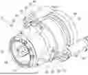
FIG. 1 a perspective view of an annular main body with a clamping jaw element for a clamping head arrangement according to the invention from the rear;
FIG. 2 a perspective view of the annular main body with the clamping jaw element of FIG. 1 from the front; and
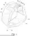
FIG. 3 a perspective view of a clamping head arrangement according to the invention.
According to FIGS. 1 and 2, a main body 12 for a clamping head arrangement 10 according to the invention can be formed annular with an interior 13 in which a cylindrical or tubular rod element (not shown) can be accommodated and clamped. Guide tracks 14 for receiving and guiding clamping jaw elements 20 are preferably formed along an inner ring side of the main body 12 with a uniform angular spacing. In the design shown, three guide tracks 14 are formed as an example.
In FIGS. 1 and 2, a clamping jaw element 20 is only inserted in one guide track 14 for reasons of clarity. According to the invention, the guide tracks 14 in the main body 12 are formed as partially cylindrical guide channels 15, i.e. with a cylindrical or partially cylindrical channel wall, wherein the respective guide channel 15 is open towards the interior 13. The opening width W of the guide channel 15 is here smaller than the cylinder diameter, which corresponds to the maximum channel width of the guide channel 15, wherein an undercut is formed in the guide channel 15.
Matching the shaping of the guide channels 15, the clamping jaw elements 20 are formed with a cylindrical or partially cylindrical guide body 22 with a guide surface 24. The outer diameter of the guide body 22 forms a fit with the inner diameter of the associated guide channel 15, so that the respective clamping jaw element 20 is precisely displaceably mounted in the guide channel 15.
The guide tracks 14 or respectively the guide channels 15 each have a longitudinal or central guide axis, which each is angled in relation to a central centre axis of the annular main body 12. This angled arrangement ensures that an axial displacement of the clamping jaw elements 20 in the guide channels 15 also leads to a radial displacement of the clamping jaw element 20 in relation to the central centre axis. Radial adjustment of this kind can, for example, bring a clamping surface 26 formed in the clamping jaw element 20 into contact with an outer side of the drill rod element to be clamped. In this way, a frictionally engaged holding of the drill rod element in the annular main body 12 is achieved.
To adjust or respectively displace the individual clamping jaw elements 20, they can have a hook arrangement 32 at their rear region, via which they can be connected to an actuator not shown in FIGS. 1 and 2. The hook arrangement 32 can be formed in one piece on the clamping jaw element 20 by inserting a groove-like recess 34 or can be attached to the clamping jaw element 20 as a separate part.
FIG. 3 shows an example of a clamping head arrangement 10 according to the invention with the annular main body 12 as shown in FIGS. 1 and 2. The clamping jaw elements 20, which are displaceably mounted in the annular main body 12, are held at their rear end region on an annular actuator 40 via the hook arrangement 32. For this purpose, bracket-like receiving mounts 36 are attached to a front side of the annular actuator 40 and form a receiving window 37 into which the hook arrangement 32 engages. A connecting device 30 for the clamping jaw element 20 on the annular actuator 40 is each formed by the hook arrangement 32 and the associated receiving mount 36.
On its rear side facing away from the clamping jaw elements 20, the annular actuator 40 is co-rotating with a drive flange 46, through which a torque can be transmitted by a rotary drive, not shown. Furthermore, the annular actuator 40 is axially displaceable via at least one adjusting cylinder 50 relative to a centre or drilling axis of the clamping head arrangement 10, which is not shown in detail.
The annular main body 12 has an end ring 18 on its front side, which end ring surrounds the interior 13 in an annular shape. On its rear side facing away from this, the annular main body 12 is firmly connected to the drive flange 46 via a connecting sleeve 19 for transmitting a torque, in particular a relatively high drilling torque. The annular actuator 40 is displaceably arranged on the outside of the connecting sleeve 19.
By axially displacing the annular actuator 40 by means of the at least one adjusting cylinder 50, the individual clamping jaw elements 20 are displaced in the partially cylindrical guide channels 15, which are not shown in detail in FIG. 3, via the respective connecting devices 30. Due to the angled arrangement of the guide channel axes to the central centre axis of the clamping head arrangement 10, the individual clamping jaw elements 20 are also adjusted radially in this relation.
By extending the at least one actuating cylinder 50, which can in particular be a hydraulic cylinder, the actuator 40 together with the clamping jaw elements 20 can be moved axially downwards towards the end ring 18, wherein the individual clamping jaw elements 20 can slide radially inwards towards the inner chamber 13 and can radially clamp a drill rod element arranged there and can hold it in a frictionally engaged manner. In this way, the drilling torque from the drive flange 46 can be transmitted to a rod element clamped in this way.
By retracting the at least one adjusting cylinder 50, the annular actuator 40 can be moved backwards again accordingly, wherein the clamping jaw elements 20 are retracted axially and also returned radially outwards to their starting position. In this reset position, a linkage element can be removed again from the clamping head arrangement 10 and a new element can be inserted.
Claims
1. Clamping head arrangement, in particular for clamping a drill rod element, having
a plurality of clamping jaw elements, each of which has a clamping surface which is designed, in particular for clamping contact with a contact side of the drill rod element, and
a main body with guide tracks, along which the clamping jaw elements are displaceably mounted, wherein the guide tracks are angled to a centre axis of the clamping head arrangement, so that displacement of the clamping jaw elements along the guide tracks causes axial and radial displacement of the clamping jaw elements with respect to the centre axis,
wherein
the clamping jaw elements are each designed with a cylindrical or partially cylindrical guide body and
the guide tracks in the main body are formed as partially cylindrical guide channels, in each of which a clamping jaw element with the cylindrical or partially cylindrical guide body is displaceably mounted.
2. Clamping head arrangement according to claim 1,
wherein
the partially cylindrical guide channels are open on the side facing the drill rod element to be clamped.
3. Clamping head arrangement according to claim 1,
wherein
the main body is designed annularly with a free interior for receiving the drill rod element and
the guide channels are open to the interior.
4. Clamping head arrangement according to claim 1,
wherein
the main body is designed in the form of a shaft or block with an outer circumferential side in which the partially cylindrical guide channels with the clamping jaw elements are arranged, wherein a tubular drill rod element can be clamped on an inner side.
5. Clamping head arrangement according to claim 1,
wherein
the clamping jaw elements are connected to at least one actuator, which is mounted so as to be displaceable relative to the main body for displacing the clamping jaw elements.
6. Clamping head arrangement according to claim 5,
wherein
the at least one actuator is axially displaceable by means of at least one actuating cylinder, in particular a hydraulic cylinder.
7. Clamping head arrangement according to claim 5,
wherein
each clamping jaw element is connected to the actuator with a clearance via a connecting device.
8. Clamping head arrangement according to claim 7,
wherein
a hook arrangement is formed on a rear region of each clamping jaw element to form the connecting device and engages in an associated receiving mount on the actuator.
9. Clamping head arrangement according to claim 1,
wherein
this clamping jaw arrangement for forming a drill drive arrangement, in particular on a drill drive carriage, can be driven in rotation via at least one rotary drive.
10. Drilling device for creating a borehole, in particular in a soil, with at least one drill rod element,
wherein
a clamping head arrangement according to claim 1 is provided.
Images & Drawings included:


Sources:
- United States Patent and Trademark Office - verify current appl. status at the USPTO↗
Similar patent applications:
Recent applications in this class:
- » 20250314134 2025-10-09
NICKEL BASED WEAR AND CORROSION PROTECTED SHANK ADAPTER - » 20240418043 2024-12-19
LATCH RELEASE MECHANISM - » 20240401417 2024-12-05
APPARATUS AND METHOD FOR SUPPORTING A COLLAR REGION OF A BLAST HOLE DURING DRILLING - » 20240141733 2024-05-02
Cable swivel - » 20230193698 2023-06-22
Drill rod coupling and method for actuating the drill rod coupling - » 20230151699 2023-05-18
Rotary percussive hydraulic drill provided with a shank equipped with coupling splines - » 20230008314 2023-01-12
Apparatus for connecting a drill pipe to the drilling drive of a drilling rig, and drilling assembly for boreholes comprising such an apparatus - » 20210348450 2021-11-11
Apparatus and method relating to managed pressure drilling - » 20210115739 2021-04-22
Couplers for connecting a power source to a drilling string - » 20210010331 2021-01-14
Downhole motor that improved thread fastening structure
Recent applications for this Assignee:
- » 20250369286 2025-12-04
DRILL DRIVE ARRANGEMENT - » 20240352797 2024-10-24
Device for generating oscillations for a construction machine and method of operation - » 20240084652 2024-03-14
Clamping head assembly for clamping a drill pipe element - » 20230358099 2023-11-09
Impact piston device for a impact drill drive - » 20220228439 2022-07-21
Rotary drive arrangement for a drill rod - » 20220178204 2022-06-09
Drill drive device for an earth drilling apparatus - » 20220152655 2022-05-19
Device for generating percussive pulses or vibrations for a construction machine - » 20190249496 2019-08-15
Drilling device for earth or rock drilling and method for retrofitting such a drilling device - » 20190085638 2019-03-21
Double head drilling device and method for producing a bore - » 20180361432 2018-12-20
Device and method for generating percussive pulses or vibrations for a construction machine