VENTED OIL CHANGE CAP
US20260063059A1
2026-03-05
19/311,648
2025-08-27
Smart Summary: A vented oil change cap helps remove oil from an oil reservoir more easily. It has a hollow plug around the main part of the cap, which connects to a neck that creates a pathway for oil to flow out. There is also a vent tube that sticks out from the bottom of the cap, allowing air to escape while oil is being drained. This design includes a separate vent channel that works with the vent tube for better gas exchange. Overall, it makes changing oil simpler and more efficient. 🚀 TL;DR
Abstract:
Systems and methods for removing oil from an oil reservoir utilizing a removable vented oil cap are described. In an aspect, a cap includes, but is not limited to, a cap body including a body portion having a hollow plug positioned around the body portion, the cap body having a bottom surface; a neck extending from the cap body, the cap body and the neck defining an oil channel extending from and through the bottom surface through the cap body and the neck to provide a continuous pathway; and a vent tube coupled with the cap body and extending beyond the bottom surface of the cap body in a direction opposite the neck, the vent tube defining an interior passage, wherein the cap body further defines a vent channel offset and separate from the oil channel, the vent channel aligning with the interior passage to provide gas exchange.
Inventors:
- Jed H. Brown 3 🇺🇸 Omaha, NE, United States
- Benjamin G Shaw 1 🇺🇸 Danbury, CT, United States
- Michael T Heckly 1 🇺🇸 Fishers, IN, United States
Applicant:
Interested in similar patents?
Get notified when new applications in this technology area are published.
Classification:
F01M11/0408 » CPC main
Component parts, details or accessories, not provided for in, or of interest apart from, groups - ; Filling or draining lubricant of or from machines or engines Sump drainage devices, e.g. valves, plugs
F01M1/10 » CPC further
Pressure lubrication Lubricating systems characterised by the provision therein of lubricant venting or purifying means, e.g. of filters
F01M2011/0425 » CPC further
Component parts, details or accessories, not provided for in, or of interest apart from, groups - ; Filling or draining lubricant of or from machines or engines; Sump drainage devices, e.g. valves, plugs; Plugs with a device facilitating the change of oil
F01M11/04 IPC
Component parts, details or accessories, not provided for in, or of interest apart from, groups - Filling or draining lubricant of or from machines or engines
Description
CROSS-REFERENCE TO RELATED APPLICATIONS
The present application claims the benefit under 35 U.S.C. § 119(e) of U.S. Provisional Application Serial No. 63/688,047, entitled VENTED OIL CHANGE CAP, filed August 28, 2024. U.S. Provisional Application Serial No. 63/688,047 is herein incorporated by reference in its entirety.
BACKGROUND
Oil caps are primarily used for sealing an oil reservoir of a motor. Oil caps are removable to facilitate oil changes and addition of oil to the oil reservoir.
SUMMARY
Systems and methods for removing oil from an oil reservoir utilizing a removable vented oil cap are described. In an aspect, a removable vented oil cap includes, but is not limited to, a cap body including a body portion having a hollow plug positioned around the body portion, the cap body having a bottom surface configured to be introduced through the opening on the oil reservoir with the hollow plug adjacent the opening; a neck extending from the cap body, the cap body and the neck defining an oil channel extending from and through the bottom surface through the cap body and the neck to provide a continuous pathway for oil to flow from the oil reservoir through the oil channel to exit the removable vented oil cap; and a vent tube coupled with the cap body and extending beyond the bottom surface of the cap body in a direction opposite the neck, the vent tube defining an interior passage through which gas exchange occurs, wherein the cap body further defines a vent channel offset and separate from the oil channel, the vent channel aligning with the interior passage of the vent tube to provide gas exchange through the vent tube and through the cap body to prevent vacuum formation during passage of oil through the oil channel.
In an aspect, a method of removing oil from an oil reservoir of an engine includes, but is not limited to, inserting a portion of a removable vented oil cap into an opening of the oil reservoir, the removeable vented oil cap including a cap body including a body portion having a hollow plug positioned around the body portion, the cap body having a bottom surface configured to be introduced through the opening on the oil reservoir with the hollow plug adjacent the opening, a neck extending from the cap body, the cap body and the neck defining an oil channel extending from and through the bottom surface through the cap body and the neck to provide a continuous pathway for oil to flow from the oil reservoir through the oil channel to exit the removable vented oil cap, and a vent tube coupled with the cap body and extending beyond the bottom surface of the cap body in a direction opposite the neck, the vent tube defining an interior passage through which gas exchange occurs, wherein the cap body further defines a vent channel offset and separate from the oil channel, the vent channel aligning with the interior passage of the vent tube to provide gas exchange through the vent tube and through the cap body to prevent vacuum formation during passage of oil through the oil channel; securing a container to the neck of the removeable vented oil cap; and tilting the engine to introduce oil from the oil reservoir into the oil channel and then into the container.
This Summary is provided to introduce a selection of concepts in a simplified form that are further described below in the Detailed Description. This Summary is not intended to identify key features or essential features of the claimed subject matter, nor is it intended to be used as an aid in determining the scope of the claimed subject matter.
DRAWINGS
The Detailed Description is described with reference to the accompanying figures. The use of the same reference numbers in different instances in the description and the figures may indicate similar or identical items.
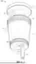
FIG. 1 is an isometric view of a bottom of a removable vented oil cap in accordance with embodiments of the present disclosure.
FIG. 2 is another isometric view of a top of the removable vented oil cap of FIG. 1.
FIG. 3 is a bottom view of the removable vented oil cap of FIG. 1.
FIG. 4A is a cross-sectional view of the removable vented oil cap of FIG. 3 taken along line 4-4 in accordance with embodiments of the present disclosure.
FIG. 4B is a cross-sectional view of the removable vented oil cap of FIG. 3 taken along line 4-4 in accordance with embodiments of the present disclosure.
FIG. 5 is a cross-sectional view of the removable vented oil cap of FIG. 1 shown interfacing with an opening in an oil reservoir to permit drainage of oil from the oil reservoir through the removable vented oil cap and the exchange of gas between the oil reservoir and the removable vented oil cap in accordance with embodiments of the present disclosure.
DETAILED DESCRIPTION
Overview
Small engine devices require proper maintenance to ensure adequate operability of the device. Some maintenance procedures are performed when the device is prepared for long-term storage, such as in preparation for a seasonal storage period, while other maintenance procedures occur more regularly. For example, one regular maintenance procedure includes changing the oil of the small engine device. Multiple methods may be used to change the oil. One method includes removing the oil reservoir cap and using a siphon pump to remove the oil from the oil fill tube and collect the oil into a container. However, using a siphon pump includes downsides, such as not being able to fully collect all the old oil, leakage of the oil as it is transferred into a collection pan for disposal, and the like. Another method for changing oil includes removal of the entire oil cap and angling the device in a manner to allow the oil to collect into an oil collection pan. This method is physically difficult to maintain an oil cap secured against an opening of the small engine while also positioning an oil collection container relative to the oil cap. A further method for changing oil include placing an oil collection cap over the oil reservoir of the small engine device and angling the device to allow the oil to collect into a container, however the container and oil collection cap can form a vacuum, preventing oil from flowing into the container, causing unpredictable flow rates of oil into the container, preventing complete drainage of oil from the container, and the like.
Each of these methods, however, may lead to oil leaking over the edge of the pan or container causing safety hazards because of slick surfaces. Oil leaks can also lead to environmental degradation due to oil accumulating in the surrounding soil or in water run-off. Spilled oil may present a direct harm to children, pets, or other animals that may contact or ingest the spilled oil. Fines may also be imposed for negative environmental impact.
Accordingly, the present disclosure is directed, at least in part, to systems and methods for changing oil from an oil reservoir (e.g., oil pan or oil sump) utilizing a removable vented oil cap configured to pass oil through the cap into a container secured to the cap while venting gases to prevent formation of a vacuum within the oil reservoir. The removeable vented oil cap defines an oil channel through a cap body of the cap to permit oil to flow from the oil reservoir through the cap body and into the container secured to the cap. A tapered plug surrounds a portion of the cap body to interface with (e.g., press against) an opening in the oil reservoir to prevent the passage of oil between the removeable vented oil cap and the oil reservoir, with the oil instead permitted to flow through the oil channel in the cap body. The cap body also defines a vent channel offset from the oil channel to permit ambient gases to pass through the vent channel while oil passes through the oil channel to prevent the formation of a vacuum in the oil reservoir. In aspects, the removable vented oil cap includes a vent tube coupled with the vent channel, with the vent tube extending from the cap body to permit the vent tube to pass into the oil reservoir for a distance beyond the level of oil in the oil reservoir (e.g., as the small engine is angled, inverted, or otherwise tilted) such that no substantial vacuum builds within the oil reservoir due to the transfer of gas through the vent tube and the vent channel.
The cap body can be formed as one or more body portions, such as through a unitary construction or as separate pieces joined together (e.g., as a screw and nut configuration, as separate pieces fused or otherwise joined together, or the like). The cap body can define the vent channel according to any suitable vent mechanism. In aspects, the cap body forms a continuous vent channel through the cap body. In aspects, the cap body and the tapered plug each form portions of the vent channel, such as to have the vent channel extend through a side portion of the removeable vented oil cap.
In aspects, the removable vented oil cap includes a cap body having a hollow tapered plug positioned between a first flange and a second flange. The cap body defines an oil channel and a vent channel offset from the oil channel, with the vent channel extending through each of the flanges in a continuous manner. The vent tube is inserted into the first flange at a bottom portion of the cap body permitting the vent tube to extend beyond the first flange while interfacing with the continuous vent channel to extend into the oil reservoir for a distance beyond the level of oil in the oil reservoir (e.g., as the small engine is angled, inverted, or otherwise tilted) such that no substantial vacuum builds within the oil reservoir due to the transfer of gas through the vent tube and out through the port in the second flange.
In aspects, the removable vented oil cap includes a hollow tapered plug into which a hollow screw of the cap body fits, where the screw interfaces with a nut of the cap body. As the nut and screw tighten, the hollow tapered plug is compressed to press fit against an opening in the engine to block the passage of oil around the removable vented oil cap, causing the oil to flow through the interior of the nut and into the interior of the hollow screw. The hollow screw can define a channel into which a portion of the vent tube fits with a second portion passing through an aperture in the screw head, permitting the vent tube to extend beyond the screw head. The hollow tapered plug defines a corresponding channel to receive an opposing end of the vent tube and further defines a port passing through one or more of a sidewall of the hollow tapered plug or a top portion of the hollow tapered plug to permit the exchange of gas through the port and the vent tube. The portion of the vent tube extending beyond the screw head can pass into the oil reservoir for a distance beyond the level of oil in the oil reservoir (e.g., as the small engine is angled, inverted, or otherwise tilted) such that no substantial vacuum builds within the oil reservoir due to the transfer of gas through the vent tube and out through the port in the hollow tapered plug.
Example Implementations
Referring generally to FIGS. 1 through 5, a removable vented oil cap (“cap 100”) is described in accordance with example implementations of the present disclosure. The cap 100 is shown generally including a cap body 102 configured to be introduced to an opening in an oil reservoir, a neck 104 configured to interface with a container to receive oil from the oil reservoir, such as when the engine housing the oil reservoir is angled inverted, or otherwise tilted, and a vent tube 106 secured to the cap body 102 and extending outwardly from the bottom of the cap 100 (e.g., in a direction opposite the neck 104) to be introduced into the oil reservoir when the cap body 102 is introduced to the opening of the oil reservoir (e.g., described further herein with respect to FIG. 5). The cap body 102 includes a first flange 108, a second flange 110, and a third flange 112, with the neck 104 extending between the second flange 110 and the third flange 112, and with a tapered plug 114 positioned about the cap body 102 between the first flange 108 and the second flange 110.
The cap body 102 and the neck 104 define an oil channel 116 extending through the cap 100 to provide a passageway for oil to drain from the oil reservoir through the cap 100 when the cap body 102 is introduced to the opening of the oil reservoir. In implementations, the oil channel 116 extends through each of the first flange 108, the second flange 110, and the third flange 112. For instance, a container can interface with the neck 104 and/or the third flange 112 to receive oil drained through the oil channel 116 (e.g., via gravity-assisted drainage with the cap 100 inverted). For example, an elastic neck of a balloon-style container can be secured to the neck 104 and/or the third flange 112, a septum or other sealed opening of a container can interface with the neck 104 and/or the third flange 112, or the like.
The cap body 102 can facilitate the exchange of gases between the external environment and the interior of the oil reservoir as oil is removed from the oil reservoir via the oil channel. For instance, the cap body 102 is shown defining a vent channel 118 offset from the oil channel 116 to permit ambient gases to pass through the vent channel 118 while oil passes through the oil channel 116 without interaction between the oil in the oil channel 116 and the gases in the vent channel 118 to prevent the formation of a vacuum in the oil reservoir. The vent tube 106 defines an interior passage 120 that fluidically couples with the vent channel 118 to provide a continuous pathway through the cap body 102 to vent the gases. For instance, the vent tube 106 can be inserted into or coupled with the vent channel 118 with an end 122 extending beyond a bottom surface 124 of the cap body 102 (e.g., beyond the first flange 108). For example, the vent tube 106 can be affixed to the first flange 108 to align the interior passage 120 with the vent channel 118 or the vent tube 106 can be inserted into a body portion 126 the cap body 102 between the first flange 108 and the second flange 110 for a portion or totality of the vent channel 118 to provide a continuous pathway through the cap body 102 to vent the gases, while leaving the end 122 of the vent tube 106 extended beyond the bottom surface 124 of the cap body 102. In implementations, the second flange 110 can also define the vent channel 118 in combination with the body portion (e.g., as shown in FIG. 4A), however the present disclosure is not limited to such configurations, where the cap body 102, the second flange 110, and the tapered plug 114 can facilitate any suitable structure for the vent channel 118, such as a substantially vertical channel from the first flange 108 through the body portion 126, and through a top surface 128 of the second flange 110 (e.g., shown in FIG. 4A), an angular channel through a sidewall of the tapered plug 114 (e.g., shown in FIG. 4B), or combinations thereof.
In implementations, the vent tube 106 extends in a direction opposite the neck 104 beyond the bottom surface 124 of the cap body 102 for a length sufficient to penetrate through oil and extend into gaseous space within the oil reservoir (e.g., as the small engine is angled, inverted, or otherwise tilted) to permit the gases to enter into the interior passage 120 without having substantial amounts of oil flow into the vent channel 118. For example, referring to FIG. 5, the cap 100 is shown with the cap body 102 inserted into an opening 50 of an oil reservoir 52 holding oil 54 therein, with the tapered plug 114 positioned at the opening to prevent the passage of oil 54 between the tapered plug 114 and the opening 50. The vent tube 106 extends from the cap body 102 such that the end 122 of the vent tube 106 extends beyond the bottom surface 124 and above a top surface 56 of the oil 54 within the oil reservoir 52, shown with a first length of vent tube (L1) extended beyond the bottom surface 124 of the cap body 102 and a second length of vent tube (L2) extended above the top surface 56 of the oil 54 within the oil reservoir 52 to position the end 122 into a void space 58 in the oil reservoir 52 that contains no oil 54. With the end 122 exposed to the void space 58, the vent channel 118 and the interior passage 120 of the vent tube 106 permit the exchange of gas 60 between an environment 62 external the oil reservoir 52 and the void space 58 to prevent the formation of a vacuum or low pressure within the oil reservoir 52 as a result of draining oil 54 through the oil channel 116 of the cap 100. The neck 104 and/or the third flange 112 can be secured with a container (not shown) to allow the oil 54 draining through the oil channel 116 of the cap 100 to be collected for appropriate disposal. For example, an elastic neck of a balloon-style container can be secured to the neck 104 and/or the third flange 112, a septum or other sealed opening of a container can interface with the neck 104 and/or the third flange 112, or the like, to align the oil channel 116 with the interior of the container for collection.
In implementations, the cap body 102 is formed from separate structures to facilitate adjustment of the tapered plug 114 between the first flange 108 and the second flange 110. For example, referring to FIG. 4B, the cap body 102 includes a nut 202 and a screw 204, with the nut 202 including the neck 104, the second flange 110, the third flange 112, and the oil channel 116 and with the screw 204 including the first flange 108 with the tapered plug 114 positioned between the nut 202 and the screw 204. The screw 204 is shown as a hollow screw where a head 206 and a threaded shank 208 of the screw 204 define a channel 206 passing through the screw 204. The oil channel 116 of the nut 202 is configured to receive the end of the threaded shank 208 such that the oil channel 116 and the channel 206 align to permit the passage of oil through each of the nut 202 and the screw 204.
The tapered plug 114 is positioned between the nut 202 and the screw 204 such that a top portion of the tapered plug 114 is positioned adjacent the second flange 110 and a bottom portion of the tapered plug 114 is positioned adjacent the head 206 of the screw 204 (e.g., forming the first flange 108). The tapered plug 114 defines an outer wall 210 that tapers inwardly from the top portion towards the bottom portion, which can provide a variety of widths to interface with different sized openings in different oil reservoirs. The tapered plug 114 is shown defining an interior channel 212 extending between and through the top portion 128 and the bottom portion 130. The interior channel 212 is sized and dimensioned to receive the end of the screw 204 such that the end passes into the tapered plug 114 and optionally through the tapered plug 114 and into the oil channel 116 of the nut 202. In implementations, the cap 100 can include a spacer between the nut 202 and the tapered plug 114. For example, a washer 214 is shown in FIG. 4B positioned between second flange 110 of the nut 202 and the top portion of the tapered plug 114.
The tapered plug 114 can be formed of a pliable material, such as a rubber or polymer such that compression of the tapered plug 114 between the nut 202 and the screw 204 can cause the outer wall 210 to extend outwardly. During use, the outer wall 210 can interface with an opening in the oil reservoir of the small engine where rotation of the nut 202 relative to the screw 204 can compress the tapered plug 114 to cause the outer wall 210 to extend outwardly to press-fit with the opening in the oil pan or oil sump to secure the cap 100 in place. While the tapered plug 114 has been described having a tapered outer wall 210, it will be appreciated that the plug can be formed according to any appropriate shape and is not limited to having a tapered outer wall 210. For example, and without limitation, the plug could be formed as a cylinder, an oval, an ellipse, an irregular shape, or another shape that corresponds to the cross section of the opening in the oil reservoir of the small engine without departing from the scope of the present disclosure.
The cap 100 is shown in FIG. 4B with the tapered plug 114 including portions of the vent channel 118. For instance, each of the vent tube 106, the screw 204, and the tapered plug 114 can include vent features to provide the vent channel 118 through which ambient gases can pass while keeping the channels 116 and 210 open to the flow of oil. For example, the tapered plug 114 can define an elongated channel 216 formed through the annular material of the tapered plug 114 between the outer wall 210 and the interior channel 212. The elongated channel 216 can be a substantially longitudinally-oriented channel in the tapered plug 114 and is shown in FIG. 4B as adjoining a portion of the interior channel 212 in a substantially vertical orientation. The elongated channel 216 intersects a cross channel 218 at the top portion of the tapered plug 114. The cross channel 218 intersects the outer wall 210 to provide a continuous channel from the outer wall 210 through the tapered plug and through the bottom portion to form the vent channel 118. Alternatively or additionally, the elongated channel 216 can extend through the top portion of the tapered plug 114 to vent out the top of the cap 100. For example, the nut 202 can include a corresponding aperture or channel (e.g., through the second flange 110) to align with the elongated channel 216 to provide a continuous channel from the top of the cap 100 through the bottom portion of the tapered plug 114.
The tapered plug 114 and the screw 204 cooperate to hold the vent tube 106 secured in the cap 100. For example, the tapered plug 114 can receive an upper portion of the vent tube 106 into the elongated channel 216 such that the interior passage 120 of the vent tube 106 is aligned with the elongated channel 216 to permit the passage of gases through the vent tube 106, the elongated channel 216, and the cross channel 218. In implementations, the vent tube 106 is secured within the elongated channel 216 via friction fit and is positioned with the upper portion beneath the cross channel 218. Alternatively, an aperture can be formed in a sidewall of the vent tube 106 with the upper portion intersecting the cross channel 218 to align the aperture with the cross channel 218.
The screw 204 can define a vent tube aperture 220 sized and dimensioned to receive the vent tube 106 into the screw 204 to pass the vent tube 106 into the elongated channel 216 of the tapered plug 114. The vent tube aperture 144 can provide additional structural stability to the vent tube 106 while permitting the end 122 of the vent tube 106 to extend beyond the head 206 of the screw 204 to facilitate venting of gases through the vent aperture 118 of the cap 100 during oil drainage. In implementations, the threaded shank 208 includes a smoothed portion (e.g., non-threaded) on a longitudinal portion of the threaded shank 208 aligned with the vent tube aperture to provide a smooth surface on the threaded shank 208 against which the vent tube 106 can rest when installed into the tapered plug 114.
While the present disclosure describes the cap 100 for use with an oil reservoir to permit oil to flow through the cap 100, the present disclosure is not limited to such uses, where the cap 100 can facilitate transfer of any fluid through the channel 116 without departing from the scope of the present disclosure. Such fluids can include, but are not limited to, fuels, consumable fluids (e.g., food items), and the like.
It will be appreciated that features described herein with respect to embodiments or implementations can be combined with any other feature or features described with respect to the same or alternative embodiments, unless context otherwise dictates, without departing from the scope of the present disclosure.
Although the subject matter has been described in language specific to structural features and/or process operations, it is to be understood that the subject matter defined in the appended claims is not necessarily limited to the specific features or acts described above. Rather, the specific features and acts described above are disclosed as example forms of implementing the claims. It is apparent that various modifications and embodiments of the structural features and/or process operations may be made by those skilled in the art without departing from the scope and spirit of the foregoing disclosure.
Claims
What is claimed is:1. A removable vented oil cap configured to interface with an opening in an oil reservoir of an engine to facilitate exchange of oil therethrough, the removeable vented cap comprising:
a cap body including a body portion having a hollow plug positioned around the body portion, the cap body having a bottom surface configured to be introduced through the opening on the oil reservoir with the hollow plug adjacent the opening;
a neck extending from the cap body, the cap body and the neck defining an oil channel extending from and through the bottom surface through the cap body and the neck to provide a continuous pathway for oil to flow from the oil reservoir through the oil channel to exit the removable vented oil cap; and
a vent tube coupled with the cap body and extending beyond the bottom surface of the cap body in a direction opposite the neck, the vent tube defining an interior passage through which gas exchange occurs,
wherein the cap body further defines a vent channel offset and separate from the oil channel, the vent channel aligning with the interior passage of the vent tube to provide gas exchange through the vent tube and through the cap body to prevent vacuum formation during passage of oil through the oil channel.
2. The removable vented oil cap of claim 1, wherein the hollow plug includes a tapered outer wall.
3. The removable vented oil cap of claim 2, wherein the tapered outer wall tapers inwardly along a direction from the neck to the vent tube.
4. The removeable vented oil cap of claim 1, wherein the cap body further includes a first flange and a second flange, wherein the body portion is positioned between the first flange and the second flange, and wherein the bottom surface is at least partially defined by the first flange.
5. The removeable vented oil cap of claim 4, wherein the first flange and the body portion define the vent channel.
6. The removeable vented oil cap of claim 5, wherein a portion of the vent tube is inserted into the vent channel defined by the first flange.
7. The removeable vented oil cap of claim 4, wherein the first flange and the hollow plug portion define the vent channel.
8. The removeable vented oil cap of claim 7, wherein a portion of the vent tube is inserted into the vent channel defined by the first flange.
9. The removeable vented oil cap of claim 4, further comprising a third flange, wherein the neck is positioned between the third flange and the second flange.
10. The removeable vented oil cap of claim 1, wherein the cap body is formed from a screw and a nut, the screw having a head and a threaded shank with the nut configured to receive the threaded shank, wherein the head, the threaded shank, and the nut forming the oil channel.
11. The removeable vented oil cap of claim 10, wherein the head of the screw defines a vent tube aperture to receive a portion of the vent tube.
12. The removable vented oil cap of claim 11, wherein the threaded shank includes a smoothed portion on a longitudinal portion of the threaded shank, the smoothed portion configured to align with the vent tube aperture.
13. The removable vented oil cap of claim 10, wherein the hollow plug is formed from a pliable material configured to be compressed between the nut and the head of the screw during rotation of the threaded shank relative to the nut.
14. A system for removing oil from an oil reservoir of an engine, comprising:
a removable vented oil cap configured to interface with an opening in the oil reservoir, the removeable vented oil cap including
a cap body including a body portion having a hollow plug positioned around the body portion, the cap body having a bottom surface configured to be introduced through the opening on the oil reservoir with the hollow plug adjacent the opening,
a neck extending from the cap body, the cap body and the neck defining an oil channel extending from and through the bottom surface through the cap body and the neck to provide a continuous pathway for oil to flow from the oil reservoir through the oil channel to exit the removable vented oil cap, and
a vent tube coupled with the cap body and extending beyond the bottom surface of the cap body in a direction opposite the neck, the vent tube defining an interior passage through which gas exchange occurs,
wherein the cap body further defines a vent channel offset and separate from the oil channel, the vent channel aligning with the interior passage of the vent tube to provide gas exchange through the vent tube and through the cap body to prevent vacuum formation during passage of oil through the oil channel; and
a container configured to be secured to the neck of the removeable vented cap to collect oil following passage of oil from the oil channel.
15. The system of claim 14, wherein the hollow plug includes a tapered outer wall.
16. The system of claim 15, wherein the tapered outer wall tapers inwardly along a direction from the neck to the vent tube.
17. The system of claim 14, wherein the cap body further includes a first flange and a second flange, wherein the body portion is positioned between the first flange and the second flange, and wherein the bottom surface is at least partially defined by the first flange.
18. The system of claim 17, wherein the first flange and the body portion define the vent channel.
19. A method of removing oil from an oil reservoir of an engine, comprising:
inserting a portion of a removable vented oil cap into an opening of the oil reservoir, the removeable vented oil cap including
a cap body including a body portion having a hollow plug positioned around the body portion, the cap body having a bottom surface configured to be introduced through the opening on the oil reservoir with the hollow plug adjacent the opening,
a neck extending from the cap body, the cap body and the neck defining an oil channel extending from and through the bottom surface through the cap body and the neck to provide a continuous pathway for oil to flow from the oil reservoir through the oil channel to exit the removable vented oil cap, and
a vent tube coupled with the cap body and extending beyond the bottom surface of the cap body in a direction opposite the neck, the vent tube defining an interior passage through which gas exchange occurs,
wherein the cap body further defines a vent channel offset and separate from the oil channel, the vent channel aligning with the interior passage of the vent tube to provide gas exchange through the vent tube and through the cap body to prevent vacuum formation during passage of oil through the oil channel;
securing a container to the neck of the removeable vented oil cap; and
tilting the engine to introduce oil from the oil reservoir into the oil channel and then into the container.
20. The method of claim 19, further comprising exchanging gases through the vent channel between the container and an external environment during introduction of the oil from the oil reservoir into the oil channel.
Images & Drawings included:


Sources:
- United States Patent and Trademark Office - verify current appl. status at the USPTO↗
Recent applications in this class:
- » 20260028925 2026-01-29
Oil Drain Plug System and Method - » 20250163835 2025-05-22
ENGINE - » 20250084775 2025-03-13
MOTOR FLUID DRAINING TOOL KIT ASSEMBLY - » 20240376836 2024-11-14
FLOW DRAINING ENHANCEMENT SYSTEM FOR ENGINE SUMP CAVITIES - » 20240344471 2024-10-17
COMMON DRAIN FOR FLUID CHAMBERS OF A MOTOR VEHICLE DRIVETRAIN FLUID SYSTEM - » 20240309782 2024-09-19
Oil Pan Drain Plug with Locking Feature - » 20240229691 2024-07-11
FLOTATION-BASED VALVE TO PREVENT OIL FROM EXITING A VEHICLE OIL SUMP - » 20240133324 2024-04-25
FLOTATION-BASED VALVE TO PREVENT OIL FROM EXITING A VEHICLE OIL SUMP - » 20240125257 2024-04-18
Fluid drain system - » 20230417164 2023-12-28
Oil Sump with Oil Drain Plug