TORCH
US20260063293A1
2026-03-05
19/317,652
2025-09-03
Smart Summary: A torch has a body that includes a handle and a main part. Inside, there is a gas valve assembly that controls the flow of gas. This assembly has different channels that connect air inlets to air outlets, allowing for independent gas paths. The air inlet connects to a gas container, providing fuel for the torch. Additionally, there are marks on the torch to show where to ignite it and how to open or close the gas flow. 🚀 TL;DR
Abstract:
A torch comprises a torch body and a gas valve assembly. The torch body comprises a handle portion and a main body portion, the gas valve assembly comprises a valve body, a first valve assembly and a second valve assembly, the valve body has an air inlet, an air outlet, a first gas path channel and a second gas path channel, and both the first gas path channel and the second gas path channel independently connect the air inlet with the air outlet. The air inlet is located at the main body portion, and is configured for connecting with a gas container. The torch also has an indication mark, comprising an ignition zone mark for indicating the ignition position of the first channel switch, an open mark for indicating the open position of the first channel switch and/or a close mark for indicating the close position of the first channel switch.
Inventors:
- Xiang Wei 3 🇨🇳 Shenzhen, China
- Yueyang Song 1 🇨🇳 Zhuhai City, China
- Xuchao Chen 1 🇨🇳 Shenzhen, China
- Xinheng Jiang 1 🇨🇳 Shenzhen, China
Applicant:
Interested in similar patents?
Get notified when new applications in this technology area are published.
Classification:
F23D14/38 » CPC main
Burners for combustion of a gas, e.g. of a gas stored under pressure as a liquid Torches, e.g. for brazing or heating
F23D14/22 » CPC further
Burners for combustion of a gas, e.g. of a gas stored under pressure as a liquid; Non-premix gas burners, i.e. in which gaseous fuel is mixed with combustion air on arrival at the combustion zone with separate air and gas feed ducts, e.g. with ducts running parallel or crossing each other
F23D14/28 » CPC further
Burners for combustion of a gas, e.g. of a gas stored under pressure as a liquid in association with a gaseous fuel source, e.g. acetylene generator, or a container for liquefied gas
Description
This application claims benefit of Chinese patent application No. CN 202422165554.9, filed on 3 Sep. 2024 and Chinese patent application No. CN 202422155742.3, filed on 3 Sep. 2024, the entire contents of which are hereby incorporated by reference.
TECHNICAL FIELD
The present application relates to the technical field of food cooking appliances, and specifically to a torch.
BACKGROUND
The torch is an ignition heating tool derived from existing gas cans (such as butane gas cans). Torches are mainly divided into two forms according to the number of gas paths of their gas valves: single gas path and dual gas path. The single gas path torch has only one gas flow path, while the dual gas path torch has two gas flow paths that may be independently ventilated, and the two independent gas paths may be used to achieve different functions respectively.
The current problem with dual gas path torches is that the air inlet of the torch gas valve is not in the vertical direction (generally in the horizontal direction at its tail), resulting in that it cannot directly connect the gas bottle near to the middle position of the torch body of the torch like the single gas path torch, so that the torch connected with the gas bottle may be directly placed upright on the desktop by the gas bottle. The dual gas path torch needs to use a bent metal tube to extend the air inlet at the tail of the gas valve to the bottom of the torch handle on the torch body (it is difficult to extend to the middle position of the torch body), which makes the dual gas path torch installed with the gas bottle unable to be placed upright on the desktop, thereby causing inconvenience in use and safety problems. In addition, the processing and installation of the bent tube will also increase the product cost.
Usually, a handheld torch is mainly a simple throttle valve composed of a valve body and a valve core, which mainly controls the movement of the valve core by the user adjusting the switch, thereby opening, closing and adjusting the size of the gas outlet volume. Due to the rigid interference fit between the valve core and the valve body, the size of the ventilation volume and the switch process cannot be quantitatively matched. Therefore, the switch usually only has direction marks for opening or closing and direction marks for adjusting the gas volume size, and cannot accurately mark the opening, closing position or ignition position. This method leads to the realization of functions such as closing, opening and ignition of the torch, all directly depending on the user's manual blind operation, which increases the difficulty of the user's operation, and often requires the user to adjust repeatedly many times to successfully perform the corresponding operation.
SUMMARY
The main technical problem solved by the present application is: the dual gas path torch cannot be placed upright on the desktop after installing the gas bottle, thereby causing inconvenience in use and safety problems, and it needs to indirectly connect the air inlet with the gas bottle through a bent tube, which will lead to an increase in product cost.
In one embodiment, a torch is provided, comprising: A torch, comprising:
A torch body, the torch body comprises a handle portion and a main body portion, the handle portion is formed by extending from one end of the main body portion; and
A gas valve assembly, the gas valve assembly comprises a valve body, a first valve assembly and a second valve assembly, the valve body comprises an air inlet, an air outlet, a first gas path channel and a second gas path channel, the first gas path channel and the second gas path channel both independently connect the air inlet with the air outlet; the first valve assembly is defined at the first gas path channel for controlling a ventilation volume of the first gas path channel, the second valve assembly is defined at the second gas path channel for controlling an opening and a closing of the second gas path channel; and
The gas valve assembly is connected in the torch body, and the air inlet is located at the main body portion, the air inlet is configured for connecting with a gas container.
In one embodiment, the main body portion extends along a first axis, and the main body portion comprises a first end and a second end oppositely defined along the first axis, the handle portion is extendedly defined at the first end of the main body portion, the air outlet is located at the second end of the main body portion, and the air inlet is located between the first end and the second end.
In one embodiment, the main body portion extends along a first axis, an opening direction of the air inlet is perpendicular to the first axis, and an opening direction of the air outlet is parallel to the first axis.
In one embodiment, the main body portion also comprises a first side and a second side, the first side and the second side are oppositely defined along a direction perpendicular to the first axis; the air inlet and the handle portion are both located at the second side of the main body portion.
In one embodiment, the valve body comprises a first mating port communicating with the first gas path channel, the first mating port is located at the first side of the main body portion, and an opening direction of the first mating port is perpendicular to the first axis; the first valve assembly is mated with the first mating port and extends into the first gas path channel from the first mating port to adjust the ventilation volume of the first gas path channel.
In one embodiment, the gas valve assembly also comprises an adjustment knob, the adjustment knob is located at the first side of the main body portion, and the adjustment knob is connected to the first valve assembly; the adjustment knob is used to drive the first valve assembly to rotate to adjust the ventilation volume of the first gas path channel.
In one embodiment, the valve body comprises a second mating port communicating with the second gas path channel, the second mating port is located between the air inlet and the first mating port in a direction perpendicular to the first axis, and an opening direction of the second mating port is parallel to the first axis; the second valve assembly is mated with the second mating port and extends into the second gas path channel from the second mating port to control the opening and closing of the second gas path channel.
In one embodiment, the gas valve assembly further comprises an adjustment button, the adjustment button is located at the first end of the main body portion, and the adjustment button is connected to the second valve assembly for opening or closing the second valve assembly when triggered.
In one embodiment, further comprising a torch tube, the torch tube is connected to the first end of the main body portion, and the torch tube is communicated with the air outlet.
In one embodiment, it also comprises a gas container, the gas container is connected to the air inlet so that an internal space of the gas container is communicated with the air inlet; and a orthographic projection of a center of gravity of the torch on the bearing surface coincides with a orthographic projection of a bottom of the gas container on the bearing surface, when the gas container is placed on a bearing surface.
According to the torch of the above embodiments, the torch comprises a torch body and a gas valve assembly. The torch body comprises a handle portion and a main body portion, and the handle portion is connected to one end of the main body portion. The gas valve assembly comprises a valve body, a first valve assembly and a second valve assembly, the valve body has an air inlet, an air outlet, a first gas path channel and a second gas path channel, and both the first gas path channel and the second gas path channel independently connect the air inlet with the air outlet. The first valve assembly is disposed in the first gas path channel for controlling the ventilation volume of the first gas path channel, and the second valve assembly is disposed in the second gas path channel for controlling the opening and closing of the second gas path channel. The gas valve assembly is connected in the gun body, and the air inlet is located at the main body portion, and the air inlet is used for connecting with a gas container. On the one hand, when using the torch, the user may control the ventilation volume of the first gas path channel through the first valve assembly, thereby achieving gear adjustment or stepless adjustment of the firepower of the torch. The user may also control the opening of the second gas path channel through the second valve assembly, so that a large amount of combustible gas flows from the second gas path channel to the air outlet, thereby greatly increasing the firepower of the torch. On the other hand, since the air inlet is disposed on the main body portion instead of on the handle portion, when the gas container is installed at the air inlet, it is easier to balance the weight of the main body portion and the handle portion carried by the gas container, thereby facilitating the upright placement of the torch on a bearing surface such as a desktop through the gas container, and further facilitating the improvement of the convenience and safety of the use of the torch. Moreover, the gas container may be directly connected to the air outlet without indirectly connecting the air inlet with the gas container through a bent tube, thereby facilitating the reduction of the production cost of the torch.
The present application provides a handheld torch to improve the convenience of user operation.
Based on the above purpose, some embodiments of the present application provide a handheld torch, comprising:
-
- A valve body, the valve body comprises a first gas channel capable of allowing a flow of gas for ignition;
- A first channel opening and closing assembly; and
- A first channel switch for the user to apply force, the first channel switch is movably installed on the valve body and forms a coupling structure with the first channel opening and closing assembly, and the first channel opening and closing assembly is capable to be driven by the first channel switch to adjust a ventilation volume of the first gas channel;
- The handheld torch comprises an indication mark, the indication mark comprises an ignition zone mark for indicating an ignition position of the first channel switch, an open mark for indicating an open position of the first channel switch and/or a close mark for indicating a close position of the first channel switch;
- The position of the first channel opening and closing assembly ensures that the ventilation volume of the first gas channel meets the ignition requirement, when the first channel switch moves to the ignition zone mark;
- The position of the first channel opening and closing assembly ensures that the first gas channel is opened, when the first channel switch moves to the open mark;
- The position of the first channel opening and closing assembly ensures that the first gas channel is closed, when the first channel switch moves to the close mark.
In some embodiments, the first channel opening and closing assembly comprises an ignition position, when the first channel switch moves to the ignition zone mark, the first channel opening and closing assembly is located at the ignition position, and the first channel opening and closing assembly opens the first gas channel, and the ventilation volume of the first gas channel meets the ignition requirement; and/or,
The first channel opening and closing assembly comprises an open position, when the first channel switch moves to the open mark, the first channel opening and closing assembly is located at the open position, and the first channel opening and closing assembly opens the first gas channel; and/or,
The first channel opening and closing assembly comprises a close position, when the first channel switch moves to the close mark, the first channel opening and closing assembly is in the close position, and the first channel opening and closing assembly closes the first gas channel.
In some embodiments, movement modes of the first channel switch comprises rotation, movement or a combination of both, and the indication mark is located on one side of at least one segment of a movement trajectory of the first channel switch, so that the position of the first channel switch is capable of being corresponded to the indication mark.
In some embodiments, the first channel opening and closing assembly comprises a sealing structure for sealing the first gas channel and a gas volume adjustment structure for adjusting the ventilation volume of the first gas channel;
The sealing structure opens the first gas channel, and the gas volume adjustment structure controls the ventilation volume in the first gas channel to meet the ignition requirement, when the first channel opening and closing assembly is located at the ignition position; the sealing structure closes the first gas channel, when the first channel opening and closing assembly is in the close position.
In some embodiments, the sealing structure comprises a first valve core, the first valve core is inserted into the first gas channel and forms a coupling structure with the first channel switch; the first valve core comprises a first sealing portion, the valve body comprises a second sealing portion facing the first sealing portion, a segment of the first gas channel penetrates the second sealing portion, and an elastic first flexible sealing member is provided between the first sealing portion and the second sealing portion;
The first sealing portion is able to separate from the second sealing portion and release the first flexible sealing member to open the first gas channel on the second sealing portion, when the first channel opening and closing assembly is located at the ignition position;
The first sealing portion is able to clamp the first flexible sealing member with the second sealing portion to close the first gas channel on the second sealing portion, when the first channel opening and closing assembly is in the close position.
In some embodiments, the gas volume adjustment structure comprises a gas volume adjustment member and a gas volume adjustment portion connected to the first valve core, the gas volume adjustment member comprises a penetrating first gas volume adjustment channel, the gas volume adjustment member is sealingly installed in the first gas channel, and the first gas channel cut off by the gas volume adjustment member communicates through the first gas volume adjustment channel; the gas volume adjustment portion is inserted into the first gas volume adjustment channel, and the gas volume adjustment portion is able to increase and decrease the gap with a cavity wall of the first gas volume adjustment channel with a movement of the first valve core to adjust the ventilation volume passing through the gap;
The ventilation volume corresponding to the minimum gap between the gas volume adjustment portion and the cavity wall of the first gas volume adjustment channel meets the ignition requirement, when the first channel opening and closing assembly is located at the ignition position; and/or,
When the first channel opening and closing assembly is in the close position, the minimum gap between the gas volume adjustment portion and the cavity wall of the first gas volume adjustment channel is 0, or the ventilation volume corresponding to the minimum gap is less than the ignition requirement, or an inner diameter of an outermost opening of the end of the first gas volume adjustment channel facing the first valve core is equal to an outer diameter of a position of the gas volume adjustment portion corresponding to the outermost opening.
In some embodiments, the sealing structure comprises a first valve core and a second valve core, the first valve core is sealingly inserted into the first gas channel; the first valve core comprises a transfer channel, and the first gas channel cut off by the first valve core communicates through the transfer channel; the first valve core comprises a third sealing portion, a segment of the transfer channel penetrates the third sealing portion, the second valve core is inserted into the transfer channel and forms a coupling structure with the first channel switch; the second valve core comprises a fourth sealing portion, and an elastic second flexible sealing member is provided between the third sealing portion and the fourth sealing portion;
The third sealing portion is able to separate from the fourth sealing portion and release the second flexible sealing member to open the transfer channel on the third sealing portion, when the first channel opening and closing assembly is located at the ignition position;
The third sealing portion is able to clamp the second flexible sealing member with the fourth sealing portion to close the transfer channel on the fourth sealing portion, when the first channel opening and closing assembly is in the close position.
In some embodiments, the second valve core is correspondingly provided with an elastic member for driving the fourth sealing portion to maintain sealing with the third sealing portion; the first channel switch comprises a movement motion, the second valve core is set on a movement path of the first channel switch, and the second valve core is capable to be driven to move by pressing the first channel switch, so that the fourth sealing portion and the third sealing portion release the second flexible sealing member to communicate with the transfer channel.
In some embodiments, the gas volume adjustment structure comprises a gas volume adjustment portion connected to the first valve core, a segment of the first gas channel is a second gas volume adjustment channel, the gas volume adjustment portion is inserted into the second gas volume adjustment channel, the first valve core forms a coupling structure with the first channel switch, and the gas volume adjustment portion is able to increase and decrease a gap with a cavity wall of the second gas volume adjustment channel with a movement of the first valve core to adjust the ventilation volume passing through the gap;
-
- the ventilation volume corresponding to the minimum gap between the gas volume adjustment portion and the cavity wall of the second gas volume adjustment channel meets the ignition requirement, when the first channel opening and closing assembly is located at the ignition position; and/or,
- when the first channel opening and closing assembly is in the close position, the minimum gap between the gas volume adjustment portion and the cavity wall of the second gas volume adjustment channel is 0, or the ventilation volume corresponding to the minimum gap is less than the ignition requirement, or an inner diameter of an outermost opening of the end of the second gas volume adjustment channel facing the first valve core is equal to an outer diameter of the position of the gas volume adjustment portion corresponding to the outermost opening.
In some embodiments, a indication range of the indication mark is at least one regional segment or at least one point; and/or,
The indication mark also comprises a first large gas volume mark for indicating the first large gas volume position of the first channel switch; the ventilation volume of the first gas channel is greater than the ignition requirement, when the first channel switch moves to the first large gas volume mark.
In some embodiments, the handheld torch also comprises a housing, the valve body, the first channel opening and closing assembly and the first channel switch are all installed on the housing, and the ignition zone mark is defined on the housing, the valve body or installed on other components of the housing.
In some embodiments, the handheld torch also comprises a second channel opening and closing assembly and a second channel switch for the user to apply force, the valve body comprises a second gas channel, an air outlet of the first gas channel and an outlet of the second gas channel are merged or separately set, the second channel switch is movably installed on the valve body and forms a coupling structure with the second channel opening and closing assembly, and the second channel opening and closing assembly is capable to be driven by the second channel switch to move to close and open the second gas channel; and
-
- the second channel opening and closing assembly comprises a second large gas volume position and a close position, the second channel opening and closing assembly opens the second gas channel, and the ventilation volume of the second gas channel is greater than the ignition requirement, when the second channel opening and closing assembly is located at the second large gas volume position; the second channel opening and closing assembly closes the second gas channel, when the second channel opening and closing assembly is in the close position.
In some embodiments, the first channel opening and closing assembly comprises a first valve core, the first valve core is inserted into the first gas channel and forms a coupling structure with the first channel switch; the first valve core comprises a first sealing portion, the valve body comprises a second sealing portion facing the first sealing portion, the first gas channel penetrates the second sealing portion, and an elastic first flexible sealing member is provided between the first sealing portion and the second sealing portion;
When the first channel opening and closing assembly is located at the ignition position, the first sealing portion is able to separate from the second sealing portion and release the first flexible sealing member to open the first gas channel on the second sealing portion, and the ventilation volume of the first gas channel meets the ignition requirement;
When the first channel opening and closing assembly is in the close position, the first sealing portion is able to clamp the first flexible sealing member with the second sealing portion to close the first gas channel on the second sealing portion.
In some embodiments, it also comprises a nozzle, and a temperature mark is defined on the nozzle, and the temperature mark is used to prompt a temperature of the nozzle.
In some embodiments, the indication mark also comprises a mode mark for indicating an use mode.
According to the handheld torch shown in the above embodiments, it has an indication mark, the indication mark comprises an ignition zone mark for indicating the ignition position of the first channel switch, an open mark for indicating the open position of the first channel switch and/or a close mark for indicating the close position of the first channel switch. The user may refer to the ignition zone mark, the open mark and/or the close mark to adjust the position of the first channel switch, and control the torch more quickly, conveniently and accurately, for example, simplifying the operation of repeatedly adjusting the ventilation volume during ignition operation, more accurately knowing whether the torch is open and/or more accurately confirming whether the torch is closed, etc.
BRIEF DESCRIPTION OF THE DRAWINGS
FIG. 1 is a structural schematic diagram of a torch from a stereoscopic perspective in one embodiment of the present application;
FIG. 2 is a structural schematic diagram of a torch from a side view perspective in one embodiment of the present application;
FIG. 3 is a sectional schematic diagram of a torch in one embodiment of the present application;
FIG. 4 is an exploded view of a torch tube and a gas valve assembly in one embodiment of the present application;
FIG. 5 is a sectional view and a partial enlarged view of a partial structure of a torch in one embodiment of the present application;
FIG. 6 is a sectional view and a partial enlarged view of a partial structure of a torch in one embodiment of the present application;
FIG. 7 is a schematic diagram of a first channel switch and an indication mark in one embodiment of the present application;
FIGS. 8 and 9 are schematic diagrams of the appearance structure of a torch in one embodiment of the present application, at this time the torch is externally connected with a gas bottle;
FIG. 10 is an exploded view of a partial structure of a torch in one embodiment of the present application;
FIG. 11 is a sectional view of a partial structure of a torch in one embodiment of the present application.
DETAILED DESCRIPTION OF THE EMBODIMENTS
The present application is further described in detail below through specific embodiments in combination with the drawings. Similar elements in different embodiments are assigned associated similar element numbers. In the following embodiments, many detailed descriptions are for better understanding of the present application. However, those skilled in the art may effortlessly recognize that some of the features may be omitted in different situations, or may be replaced by other elements, materials, methods. In some cases, some operations related to the present application are not shown or described in the specification, which is to avoid the core part of the present application being overwhelmed by excessive descriptions, and for those skilled in the art, it is not necessary to describe these related operations in detail, and they may fully understand the related operations according to the description in the specification and the general technical knowledge in the art.
In addition, the features, operations or characteristics described in the specification may be combined in any appropriate manner to form various embodiments. At the same time, the steps or actions in the method description may also be exchanged or adjusted in sequence in a manner obvious to those skilled in the art. Therefore, the various sequences in the specification and drawings are only for clearly describing a certain embodiment, and do not mean that they are necessary sequences, unless otherwise specified that a certain sequence must be followed.
The numbering of components in this article, such as “first”, “second”, etc., is only used to distinguish the described objects and does not have any sequential or technical meaning. The “connection” and “coupling” mentioned in the present application, unless otherwise specified, include direct and indirect connection (coupling).
The present embodiment provides a torch.
Please refer to FIGS. 1-4, the torch comprises a torch body 100 and a gas valve assembly 200.
Please refer to FIGS. 1-4, the torch body 100 comprises a handle portion 110 and a main body portion 120, and the handle portion 110 is connected to one end of the main body portion 120. The gas valve assembly 200 comprises a valve body 210, a first valve assembly 220 and a second valve assembly 230, the valve body 210 has an air inlet 211, an air outlet 212, a first gas path channel 213 and a second gas path channel 214, and both the first gas path channel 213 and the second gas path channel 214 independently connect the air inlet 211 with the air outlet 212. The first valve assembly 220 is defined in the first gas path channel 213 for controlling the ventilation volume of the first gas path channel 213, and the second valve assembly 230 is defined in the second gas path channel 214 for controlling the opening and closing of the second gas path channel 214. The gas valve assembly 200 is connected in the torch body 100, and the air inlet 211 is located at the main body portion 120, and the air inlet 211 is configured for connecting with a gas container 400.
On the one hand, when using the torch, the user may control the ventilation volume of the first gas path channel 213 through the first valve assembly 220, thereby achieving gear adjustment or stepless adjustment of the firepower of the torch. The user may also control the opening of the second gas path channel 214 through the second valve assembly 230, so that a large amount of combustible gas flows from the second gas path channel 214 to the air outlet 212, thereby greatly increasing the firepower of the torch. On the other hand, since the air inlet 211 is defined on the main body portion 120 instead of on the handle portion 110, when the gas container 400 is installed at the air inlet 211, it is easier to balance the weight of the main body portion 120 and the handle portion 110 carried by the gas container 400, thereby facilitating the upright placement of the torch on a bearing surface such as a desktop through the gas container 400, and further facilitating the improvement of the convenience and safety of the use of the torch. Moreover, the gas container 400 may be directly connected to the air outlet 212 without indirectly connecting the air inlet 211 with the gas container 400 through a bent tube, thereby facilitating the reduction of the production cost of the torch.
Among them, “the first gas path channel 213 and the second gas path channel 214 both independently connect the air inlet 211 with the air outlet 212” may be understood as the first gas path channel 213 and the second gas path channel 214 both being able to independently achieve on-off or ventilation volume adjustment control.
Please refer to FIGS. 3 and 4, in one embodiment, the first valve assembly 220 may select a valve core 221, and the second valve assembly 230 may select a check valve 231. In another embodiment, the first valve assembly 220 and the second valve assembly 230 may also be configured as the same valve, for example, both the first valve assembly 220 and the second valve assembly 230 are configured as check valves 231.
It should be noted that the torch may or may not comprise the gas container 400, that is, the gas container 400 may be regarded as a component of the torch, and at this time the torch comprises the gas container 400. The gas container 400 may also be regarded as an independent consumable used in cooperation with the torch, and at this time the torch does not comprise the gas container 400. Specifically, the gas container 400 may select a common gas bottle.
Please refer to FIGS. 1-3, in one embodiment, when the gas container 400 is regarded as a component of the torch, the torch also comprises the gas container 400, and the gas container 400 is connected to the air inlet 211 so that the internal space of the gas container 400 communicates with the air inlet 211. When the gas container 400 is placed on a bearing surface, the orthographic projection of the center of gravity of the torch on the bearing surface coincides with the orthographic projection of the bottom of the gas container 400 on the bearing surface.
On the one hand, when the user connects the gas container 400 to the air inlet 211, the internal space of the gas container 400 communicates with the air inlet 211, so that the combustible gas in the gas container 400 may flow from the air inlet 211 into the cavity, and flow to the air outlet 212 through the first gas path channel 213 and/or the second gas path channel 214 for ignition. On the other hand, after the user uses the torch, the user may place the torch upright on a bearing surface such as a desktop or a countertop through the gas container 400. At this time, since the orthographic projection of the center of gravity of the torch on the bearing surface coincides with the orthographic projection of the bottom of the gas container 400 on the bearing surface, the torch is not easy to tip over, thereby facilitating the improvement of the convenience and safety of the placement of the torch.
Please refer to FIGS. 1 and 2, in one embodiment, the main body portion 120 extends along a first axis, and the main body portion 120 has a first end 121 and a second end 122 oppositely defined along the first axis, the handle portion 110 is extendedly defined at the first end 121 of the main body portion 120, the air outlet 212 is located at the second end 122 of the main body portion 120, and the air inlet 211 is located between the first end 121 and the second end 122.
On the one hand, the handle portion 110 is extendedly defined at the first end 121 of the main body portion 120, and the air inlet 211 is located between the first end 121 and the second end 122, so that the air inlet 211 is not located on the handle portion 110, and it is convenient to achieve weight balance between the first end 121 and the second end 122, thereby facilitating ensuring that the torch may be stably placed on the bearing surface through the gas container 400. On the other hand, the handle portion 110 and the air outlet 212 are respectively located at the first end 121 and the second end 122, so that when the user holds the handle portion 110 and operates the torch, the air outlet 212 that ejects flames is farther away from the user's hand, thereby facilitating the improvement of the safety of the torch. Specifically, the “first axis” may be regarded as the axis L1 in FIG. 2.
Please refer to FIGS. 1 and 2, in one embodiment, the main body portion 120 extends along a first axis, the opening direction of the air inlet 211 is perpendicular to the first axis, and the opening direction of the air outlet 212 is parallel to the first axis.
The air inlet 211 is opened in a direction perpendicular to the first axis, that is, the air inlet 211 is opened in the vertical direction when the torch is placed upright in actual application scenarios, which facilitates the direct connection of the gas container 400 to the air inlet 211. In the traditional scheme, when the air inlet 211 is opened horizontally, it is necessary to change the air inlet direction through a bent tube, and the gas container 400 may only be indirectly connected to the air inlet 211 through the bent tube, so it may be seen that the scheme of the present embodiment may simplify the installation structure and reduce the production cost. Moreover, opening the air outlet 212 in a direction parallel to the first axis conforms to the user's operating habits when operating the torch, thereby facilitating ensuring the user's experience when operating the torch.
Please refer to FIGS. 1 and 2, in one embodiment, the main body portion 120 also has a first side 123 and a second side 124, the first side 123 and the second side 124 are oppositely defined along a direction perpendicular to the first axis. The air inlet 211 and the handle portion 110 are both located at the second side 124 of the main body portion 120.
When the user places and uses the torch, the second side 124 of the main body portion 120 is usually located below the first side 123, which on the one hand conforms to the user's operating habits, that is, when the user holds the handle portion 110, most of the hand and the handle portion 110 are located below the main body portion 120, thereby facilitating the user's operation of the torch. On the other hand, when the gas container 400 is installed at the air inlet 211, it is also located at the lower part of the torch, which not only facilitates ensuring the safety of the torch, but also facilitates placing the torch upright on the bearing surface through the gas container 400 after using the torch.
Please refer to FIGS. 2-4, in one embodiment, the valve body 210 has a first mating port 215 communicating with the first gas path channel 213, the first mating port 215 is located at the first side 123 of the main body portion 120, and the opening direction of the first mating port 215 is perpendicular to the first axis. The first valve assembly 220 mates with the first mating port 215 and extends into the first gas path channel 213 from the first mating port 215 to adjust the ventilation volume of the first gas path channel 213. When it is necessary to adjust the firepower of the torch, the user may adjust the opening degree of the first gas path channel 213 through the first valve assembly 220, thereby adjusting the ventilation volume of the first gas path channel 213, and then achieving the purpose of adjusting the firepower of the torch. Moreover, the first valve assembly 220 and the first mating port 215 are defined at the first side 123 of the main body portion 120, that is, in actual application scenarios, the first valve assembly 220 is located on the upper side of the main body portion 120, thereby facilitating the user's observation and operation of the first valve assembly 220.
Please refer to FIGS. 2-4, in one embodiment, the gas valve assembly 200 also comprises an adjustment knob 240, the adjustment knob 240 is located at the first side 123 of the main body portion 120, and the adjustment knob 240 is connected to the first valve assembly 220. The adjustment knob 240 is used to drive the first valve assembly 220 to rotate to adjust the ventilation volume of the first gas path channel 213.
When using the torch, the user may rotate the adjustment knob 240 to drive the first valve assembly 220 to rotate, thereby changing the opening degree of the first gas path channel 213, so that the ventilation volume of the first gas path channel 213 changes, and then the stepless adjustment of the firepower of the torch may be achieved. Specifically, the first valve assembly 220 may select a valve core 221 that is rotationally assembled at the first mating port 215 and may change the opening degree through its own rotation.
Please refer to FIGS. 2-4, in one embodiment, the valve body 210 has a second mating port 216 communicating with the second gas path channel 214, the second mating port 216 is located between the air inlet 211 and the first mating port 215 in a direction perpendicular to the first axis, and the opening direction of the second mating port 216 is parallel to the first axis. The second valve assembly 230 mates with the second mating port 216 and extends into the second gas path channel 214 from the second mating port 216 to control the opening and closing of the second gas path channel 214. When using the torch, the user may open or close the second gas path channel 214 through the second valve assembly 230. When the second gas path channel 214 is opened, a large amount of combustible gas may flow to the air outlet 212 through the second gas path channel 214, thereby increasing the firepower of the torch. Since the second mating port 216 is located between the air inlet 211 and the first mating port 215 in a direction perpendicular to the first axis, that is, the second mating port and the second valve assembly 230 are roughly located inside the main body portion 120 in the vertical direction, thereby facilitating the setting of a transmission member 260 for triggering the second valve assembly 230 inside the main body portion 120.
Please refer to FIGS. 2-4, in one embodiment, the gas valve assembly 200 also comprises an adjustment button 250, the adjustment button 250 is located at the first end 121 of the main body portion 120, and the adjustment button 250 is connected to the second valve assembly 230 for opening or closing the second valve assembly 230 when triggered.
When using the torch, the user may press the adjustment button to open or close the second valve assembly 230. When the second valve assembly 230 is opened, a large amount of combustible gas may flow to the air outlet 212 through the second gas path channel 214, thereby increasing the firepower of the torch, and then realizing the “one-key big fire” function of the torch. It not only expands the function of the torch, but also provides the user with more flexible operation methods. Specifically, the adjustment button 250 may indirectly drive the second valve assembly 230 to open and close through a transmission member 260 set in the main body portion 120, or may be directly connected to the second valve assembly 230, and the second valve assembly 230 may select a check valve 231.
Please refer to FIGS. 1-3, in one embodiment, the torch also comprises a torch tube 300, the torch tube 300 is connected to the first end 121 of the main body portion 120, and the torch tube 300 communicates with the air outlet 212.
On the one hand, the torch tube 300 communicates with the air outlet 212, so that the torch tube 300 plays a role in constraining and guiding the ejected flames, thereby facilitating the improvement of the safety of the torch. On the other hand, when the gas container 400 is connected between the first end 121 and the second end 122 of the main body portion 120, since the torch tube 300 is connected to the first end 121 of the main body portion 120, it also plays the effect of weight balancing with the handle portion 110 at the second end 122 of the main body portion 120, thereby facilitating increasing the stability when the torch is placed upright on the bearing surface through the gas container 400.
In the usual use process of a handheld torch (referred to as torch), the switch and size of the ventilation volume in the torch are controlled by the user based on feeling. Due to the difficulty of quickly and accurately controlling the ventilation volume to the desired size in this blind operation, it often requires the user to operate repeatedly many times, increasing the difficulty and inconvenience of control. For example, when the torch is ignited, the air output volume needs to be controlled within a certain range to cooperate with the ignition switch for ignition. Due to the high difficulty of manual control, the requirements for the user are high. For another example, when closing the torch, the user may not be able to close the torch in place at one time, resulting in air leakage. For another example, when opening the torch, the user may not be able to open the torch in place at one time, resulting in no gas output and inability to ignite and use.
Therefore, in some embodiments of the present application, an indication mark is set on the torch, the indication mark comprises an ignition zone mark for indicating the ignition position of the first channel switch, an open mark for indicating the open position of the first channel switch and/or a close mark for indicating the close position of the first channel switch. The user may refer to the ignition zone mark, the open mark and/or the close mark to adjust the position of the first channel switch, and control the torch more quickly, conveniently and accurately, for example, simplifying the operation of repeatedly adjusting the ventilation volume during ignition operation, more accurately knowing whether the torch is open and/or more accurately confirming whether the torch is closed, etc.
Please refer to FIGS. 5 and 6, some embodiments of the present application provide a handheld torch, which comprises a valve body 1, a first channel opening and closing assembly 2 and a first channel switch 3 for the user to apply force. Of course, in other embodiments, the handheld torch may also selectively have other structures as needed, such as a housing 4 (see FIGS. 8, 9), a nozzle 500 (see FIGS. 8, 9), a gas bottle connector 600 (see FIGS. 8, 9), etc.
The valve body 1 has a first gas channel A for gas flow for ignition. The valve body 1 may be used to form the first gas channel A or more gas channels. The valve body 1 may be an independent part or may be formed by splicing and combining multiple parts. In the embodiments shown in FIGS. 5 and 6, the first gas channel A may be configured for the flow of gas for ignition, that is, the air output volume of the torch during ignition is determined by the ventilation volume of the first gas channel A. In some embodiments, the first gas channel A may only be used as a gas channel for ignition, or in addition to being used as a gas channel for ignition, the first gas channel A may also be used as a gas channel during normal combustion.
Please refer to FIGS. 5 and 6, the first channel switch 3 is movably installed on the valve body 1 and forms a coupling structure with the first channel opening and closing assembly 2, that is, the movement of the first channel switch 3 may drive the first channel opening and closing movement, so that the user is able to drive the first channel opening and closing assembly 2 to move through the first channel switch 3 to adjust the ventilation volume of the first gas channel A. For example, increase the ventilation volume of the first gas channel A, or decrease the ventilation volume of the first gas channel A (including adjusting the ventilation volume of the first gas channel A to 0, that is, closing the first gas channel A).
Please refer to FIG. 7, the torch has an indication mark (such as labels 11, 12, 13, 14, etc. in the figure). The indication mark at least comprises an ignition zone mark 11 for indicating the ignition position of the first channel switch 3, an open mark for indicating the open position of the first channel switch 3 and/or a close mark for indicating the close position of the first channel switch.
When the first channel switch 3 moves to the ignition zone mark 11, the position of the first channel opening and closing assembly 2 ensures that the ventilation volume of the first gas channel A meets the ignition requirement. The user may refer to the ignition zone mark 11 to adjust the position of the first channel switch 3. When the first channel switch 3 moves to the ignition zone mark 11, the user may directly perform ignition, improving the convenience of the user's ignition operation.
When the position of the first channel switch 3 corresponds to the ignition zone mark 11, the first channel opening and closing assembly 2 is at the ignition position, and the first channel opening and closing assembly 2 opens the first gas channel A, with the ventilation volume of the first gas channel A meeting the ignition requirements. At this time, the ventilation volume within the torch (which determines the gas output of the torch) meets the ignition requirements. The ventilation volume required for ignition refers to the gas flow rate within the range necessary for ignition at that moment. The specific value of the ventilation volume required for ignition can be referenced from existing technology and will not be elaborated here.
When the first channel switch 3 moves to the open mark, the position of the first channel opening and closing assembly 2 ensures that the first gas channel A is opened. When the first channel switch 3 moves to the close mark, the position of the first channel opening and closing assembly 2 ensures that the first gas channel A is closed.
The torch may have both an open mark and a close mark, or it may have only one of them. Referring to FIG. 7, in some embodiments, the figure shows a mark 13, which can serve as either an open mark or a close mark.
For example, when the mark 13 is an open mark, and the first channel switch 3 moves from the open direction (counterclockwise rotation as shown in FIG. 7) to the mark 13, the first gas channel A is opened. If the first channel switch 3 has not moved to the mark 13 from the open direction, it indicates that the first gas channel A remains closed.
When the mark 13 is a close mark, and the first channel switch 3 moves from the close direction (clockwise rotation as shown in FIG. 7) to the mark 13, the first gas channel A is closed. If the first channel switch 3 has not moved to the mark 13 from the close direction, it indicates that the first gas channel A remains open.
The indication marks can include, but are not limited to, sensory marks such as sound marks, color marks, text marks, or tactile marks. Tactile marks refer to a distinct feel, such as a click or resistance, that draws attention when the first channel switch 3 moves to the corresponding position. In some embodiments, the tactile mark may be visible or invisible.
Furthermore, in some embodiments, the positions of the first channel opening and closing assembly 2 can be further divided in detail. For example, in some embodiments, the first channel opening and closing assembly 2 has an ignition position. When the first channel switch 3 moves to the ignition zone mark, the first channel opening and closing assembly 2 is at the ignition position, opens the first gas channel A, and the ventilation volume of the first gas channel A meets the ignition requirements, allowing the user to ignite directly.
And/or, the first channel opening and closing assembly 2 has an open position. When the first channel switch 3 moves to the open mark, the first channel opening and closing assembly 2 is at the open position, and the first channel opening and closing assembly 2 opens the first gas channel A. In some embodiments, this open position may indicate the position where the first channel opening and closing assembly 2 just opens the first gas channel A. In other embodiments, at this open position, the ventilation volume of the first gas channel A may be less than the ignition requirement. Alternatively, in other embodiments, at this open position, the ventilation volume of the first gas channel A may also meet the ignition requirements.
And/or, the first channel opening and closing assembly 2 has a close position. When the first channel switch 3 moves to the close mark, the first channel opening and closing assembly 2 is at the close position, and the first channel opening and closing assembly 2 closes the first gas channel A.
Furthermore, the indication mark is typically placed on one side of the movement trajectory of the first channel switch 3, so that the user can align the position of the first channel switch 3 with the indication mark. The movement mode of the first channel switch 3 can be arbitrary, as long as it can drive the first channel opening and closing assembly 2 to open or close the first gas channel A and adjust the ventilation volume of the first gas channel A.
In some exemplary embodiments, the movement mode of the first channel switch 3 includes rotation, linear movement, or a combination of both, and the indication mark is located on one side of at least one segment of the movement trajectory of the first channel switch 3, such as on the side of a rotational movement trajectory, a linear movement trajectory, or a combination of both, to allow the user to better align the position of the first channel switch 3 with the indication mark. The direction of the rotational axis is not limited and can be vertical, horizontal, or inclined. Similarly, the direction of the linear movement is not limited and can be vertical, horizontal, or inclined.
Furthermore, in some embodiments, the first channel switch 3 can use rotational movement to adjust the ventilation volume of the first gas channel A, achieving fine-tuning and improving control accuracy. For example, in the embodiments shown in FIGS. 1-3, the first channel switch 3 is a knob, and the indication mark is placed on one side of the rotational movement trajectory of the first channel switch 3. Additionally, the first channel switch 3 can also be a lever or other switch structure capable of rotational adjustment. Of course, in other embodiments, the first channel switch 3 can also adjust the ventilation volume of the first gas channel A through pressing or sliding along a linear trajectory.
Regarding another aspect of the indication mark, in some embodiments, the indication range of each indication mark is at least one regional segment or at least one point. For example, the indication range of the ignition zone mark 11 is at least one regional segment or at least one point. When the ignition zone mark 11 is a regional segment, as long as the first channel switch 3 aligns with this segment, it indicates that ignition is possible. This segment reduces the precision required for the user to control the first channel switch 3. When the ignition zone mark 11 is a point, as long as the first channel switch 3 aligns with this point, it indicates that ignition is possible. For example, in the embodiment shown in FIG. 7, the indication range of the ignition zone mark 11 is at least one arc-shaped regional segment. At this time, the first channel switch 3 is a knob, and when it rotates to within the regional segment of the ignition zone mark 11, it indicates that ignition is possible. Similarly, the indication range of the open mark and the close mark can also be at least one regional segment or at least one point.
Referring to FIG. 7, in some embodiments, to make it more convenient to align the first channel switch 3 with the indication mark, a reference mark 301 can be provided on the first channel switch 3. The reference mark 301 can be a line, graphic, or structural mark (such as a protrusion or groove), as long as it serves an indicative purpose. For example, when the reference mark 301 aligns with the corresponding indication mark (e.g., ignition zone mark 11, open mark, or close mark), it indicates that the first channel switch 3 has moved to the corresponding indication mark (e.g., ignition zone mark 11, open mark, or close mark).
Furthermore, referring to FIG. 7, in some embodiments, the torch has a first large gas volume mark 12 to indicate the first large gas volume position of the first channel switch 3. When the first channel switch 3 moves to the first large gas volume mark 12, the ventilation volume of the first gas channel A is greater than the ignition requirement. In this embodiment, the first gas channel A not only facilitates the ignition operation but can also increase the ventilation volume to achieve normal combustion functions. When the first large gas volume mark 12 is specified, the user can more quickly and clearly determine the current ventilation volume status of the first gas channel A. Additionally, the torch can include other indication marks as needed, such as a maximum gas volume mark indicating the maximum ventilation volume or a mode mark indicating the usage mode corresponding to the flame produced by the ventilation volume. As shown in FIG. 7, the mode mark may comprise a sear mark 14, prompting the user that the flame corresponding to this ventilation volume size may be configured for cooking of caramelizing food, and the mode mark may also be a low-temperature slow roasting mode mark or a steak mode mark, etc., for prompting the ventilation volume required for low-temperature slow roasting fire or steak cooking. It may be understood that the indication mark may also comprise marks for other functions.
Regarding the position of the indication mark, it may be set on any component of the torch, as long as it may satisfy that the user is able to correspond the first channel switch 3 with the indication mark. For example, in some embodiments, please refer to FIGS. 4 and 5, the torch also has a housing 4, the aforementioned valve body 1, first channel opening and closing assembly 2 and first channel switch 3 are all installed on the housing 4, and the indication mark is set on the housing 4, the valve body 1 or installed on other components of the housing 4.
More specifically, in the embodiments shown in FIGS. 5, 8 and 9, the housing 4 comprises a cover plate 410 set around the first channel switch 3, and the first channel switch 3 is movably set relative to the cover plate 410. In these embodiments, the indication mark may be set on the cover plate 410, and the indication mark is located on the peripheral side of the first channel switch 3, so that the user may better correspond the first channel switch 3 with each indication mark.
On the other hand, the inventor of the present application, after repeated research and experiments, found that the reason why no ignition indication mark is set in the existing torch is mainly because the valve core and the valve body 1 in these torches are in hard contact, and the closing of the gas channel is achieved through the extrusion deformation of the contact surface between the valve core and the valve body 1. After long use, it is extremely easy to cause wear of the valve body 1 and the valve core, so that the position of tightening the valve core each time the gas valve is sealed is not fixed, so various indication marks cannot be accurately given to the user, and as the use time increases, a larger torque is generally required to tighten and open the valve core in the later stage, and the use experience will also be greatly reduced. With multiple uses, the wear is also aggravated, which will also affect the stability of the air output volume.
In order to solve this technical problem, the present application provides multiple embodiments regarding the first channel opening and closing assembly.
In some embodiments, the first channel opening and closing assembly 2 comprises a sealing structure for sealing the first gas channel A and a gas volume adjustment structure for adjusting the ventilation volume of the first gas channel A. Alternatively, in other embodiments, the gas volume adjustment structure may not be set separately, and the sealing structure, while completing the opening of the first gas channel A, is also used as a gas volume adjustment structure, that is, the opening degree opened by the sealing structure itself may also be configured for gas volume adjustment.
More specifically, when the first channel opening and closing assembly 2 comprises a sealing structure for sealing the first gas channel A and a gas volume adjustment structure for adjusting the ventilation volume of the first gas channel A. The gas volume adjustment structure and the sealing structure are set separately, the sealing structure is responsible for sealing, and it does not affect the control of the gas volume by the gas volume adjustment structure. The gas volume adjustment structure is only configured for adjusting the gas volume, and it is not used as the main sealing component, so there is no wear or less wear. In some embodiments, the control of the sealing structure may be separated from the control of the gas volume adjustment structure. Even if the sealing structure is worn, the gas volume adjustment structure may ensure more accurate gas volume control, thereby ensuring that the given indication mark is always accurate. Of course, in other embodiments, the sealing method of the sealing structure may also be improved to reduce the wear of the sealing structure.
Further, when the first channel opening and closing assembly 2 is located at the ignition position, the sealing structure opens the first gas channel A, and the gas volume adjustment structure controls the ventilation volume in the first gas channel A to meet the ignition requirement; when the first channel opening and closing assembly 2 is in the close position, the sealing structure closes the first gas channel A. Among them, when the first channel opening and closing assembly 2 is in the close position, since the sealing structure has completed the sealing of the first gas channel A, the gas volume adjustment structure may not be closed at this time, and kept at a certain opening degree, for example, kept at the opening degree required for the ignition position, and the next time the sealing structure is opened, ignition may be performed directly. Of course, when the first channel opening and closing assembly 2 is in the close position, the gas volume adjustment structure may also be closed with the movement of the first channel opening and closing assembly 2.
Please refer to FIGS. 5, 10 and 11, in some embodiments, the sealing structure comprises a first valve core 2101, the first valve core 2101 is inserted into the first gas channel A, and a gap for gas to pass through is formed between the first valve core 2101 and the first gas channel A, for example, in the structure shown in FIG. 5, the peripheral side of the first valve core 2101 is threadedly connected to the cavity wall of the first gas channel A, the threaded connection is a non-sealing connection, and a gap for gas to pass through is formed between the first valve core 2101 and the cavity wall of the first gas channel A. Of course, in other embodiments, a transfer channel for communicating the first gas channel A may also be set on the first valve core 2101, etc.
The first valve core 2101 forms a coupling structure with the first channel switch 3, that is, the first channel switch 3 may be linked with the first valve core 2101. The first valve core 2101 has a first sealing portion 2111, and the valve body 1 has a second sealing portion 1101 facing the first sealing portion 2111, and a segment of the first gas channel A penetrates the second sealing portion 1101.
Please refer to FIG. 5, in order to reduce wear during sealing, in some embodiments, an elastic first flexible sealing member 241 (such as a sealing ring, sealing block or other sealing member) is provided between the first sealing portion 2111 and the second sealing portion 1101, and the first flexible sealing member 241 may be installed on the first sealing portion 2111, or on the second sealing portion 1101, or movably set between the two. In the embodiment shown in FIG. 5, the first flexible sealing member 241 is sleeved on the first valve core 2101 and moves with the first valve core 2101.
When the first channel opening and closing assembly 2 is located at the ignition position, the first sealing portion 2111 is able to separate from the second sealing portion 1101 and release the first flexible sealing member 241 to open the first gas channel A on the second sealing portion 1101, thereby opening the entire first gas channel A.
When the first channel opening and closing assembly 2 is in the close position, please see FIG. 5, at this time the first sealing portion 2111 is able to clamp the first flexible sealing member 241 with the second sealing portion 1101 to close the first gas channel A on the second sealing portion 1101, thereby closing the entire first gas channel A.
In this embodiment, when the first channel opening and closing assembly 2 is in the close position, the first sealing portion 2111 and the second sealing portion 1101 no longer directly contact, but achieve the sealing effect by squeezing the flexible sealing member between them, so that the relative position of the first sealing portion 2111 and the second sealing portion 1101 is basically fixed each time it is closed, and there will be no wear problem.
Further, please refer to FIGS. 5 and 10, in some embodiments, the gas volume adjustment structure comprises a gas volume adjustment member 2201 and a gas volume adjustment portion 2301 connected to the first valve core 2101. The gas volume adjustment member 2201 has a penetrating first gas volume adjustment channel 2311, the gas volume adjustment member 2201 is sealingly installed in the first gas channel A, and the first gas channel A cut off by the gas volume adjustment member 2201 communicates through the first gas volume adjustment channel 2311. The gas volume adjustment portion 2301 is inserted into the first gas volume adjustment channel 2311, and the gas volume adjustment portion 2301 is able to increase and decrease the gap with the cavity wall of the first gas volume adjustment channel 2311 with the movement of the first valve core 2101 to adjust the ventilation volume passing through the gap.
In this embodiment, the gas volume adjustment portion 2301 and the first valve core 2101 are integrally formed, but in other embodiments, the two may also be fixedly connected or transmission connected to each other, as long as they may move integrally. Since the first valve core 2101 and the gas volume adjustment portion 2301 move integrally in this embodiment, the opening and closing of the first gas channel A by the first valve core 2101 and the gas volume control of the first gas volume adjustment channel 2311 by the gas volume adjustment portion 2301 are performed synchronously, which may simplify the structure and also simplify the user's operation steps and difficulty.
Further, please refer to FIGS. 5 and 10, in some embodiments, along the axial direction of the first gas volume adjustment channel 2311, the outer diameter of the gas volume adjustment portion 2301 decreases from the side where the first valve core 2101 is located to the side where the gas volume adjustment member 2201 is located. This decrease may be smooth, for example, the gas volume adjustment portion 2301 in FIG. 10 is a conical structure. In addition, the decrease may also be stepwise, for example, forming a pagoda-shaped structure, etc.
In the embodiment shown in FIG. 5, the first gas volume adjustment channel 2311 is a through hole with consistent inner diameter. Of course, in other embodiments, the first gas volume adjustment channel 2311 may also be other shapes, for example, it may be an inverted cone shape with a large top and a small bottom or other shapes. The gap between the outermost opening of the end of the first gas volume adjustment channel 2311 facing the first valve core 2101 and the gas volume adjustment portion 2301 is the main position for limiting the ventilation volume. In the state shown in FIG. 5, the outermost opening of the end of the first gas volume adjustment channel 2311 facing the first valve core 2101 is in contact with the outer wall of the gas volume adjustment portion 2301, that is, the ventilation volume at this time is 0, that is, the first valve core 2101 is in the zero position. When the first valve core 2101 moves upward, the gas volume adjustment portion 2301 also moves upward, and the gap between the outermost opening of the end of the first gas volume adjustment channel 2311 facing the first valve core 2101 and the outer wall of the gas volume adjustment portion 2301 gradually increases, thereby increasing the ventilation volume.
Based on the matching structure of the first gas volume adjustment channel 2311 and the gas volume adjustment portion 2301, in some embodiments, when the first channel opening and closing assembly 2 is located at the ignition position, the ventilation volume corresponding to the minimum gap between the gas volume adjustment portion 2301 and the cavity wall of the first gas volume adjustment channel 2311 meets the ignition requirement;
And/or, when the first channel opening and closing assembly 2 is in the close position: the minimum gap between the gas volume adjustment portion 2301 and the cavity wall of the first gas volume adjustment channel 2311 is 0, or the ventilation volume corresponding to the minimum gap is less than the ignition requirement.
Alternatively, in some embodiments, when the first channel opening and closing assembly 2 is in the close position, the inner diameter of the outermost opening of the end of the first gas volume adjustment channel 2311 facing the first valve core 2101 is equal to the outer diameter of the position of the gas volume adjustment portion 2301 corresponding to the opening. At this time, no extrusion deformation or only slight deformation occurs between the mouth wall of the outermost opening of one end of the first gas volume adjustment channel 2311 and the gas volume adjustment portion 2301, so that the wear consumption between the two may be reduced to avoid inaccuracy of gas volume adjustment.
Please refer to FIG. 5, in some more specific embodiments, the second sealing portion 1101 is a boss structure, the gas volume adjustment member 2201 is located on one side of the second sealing portion 1101, and the gas volume adjustment portion 2301 penetrates the second sealing portion 1101 from the side of the second sealing portion 1101 away from the gas volume adjustment member 2201 and is inserted into the first gas volume adjustment channel 2311 of the gas volume adjustment member 2201.
The movement of the first valve core 2101 on the valve body 1 may be either rotation or movement along part of the first gas channel A. Please refer to FIGS. 5 and 11, in some embodiments, the first valve core 2101 is threadedly connected to the valve body 1, and the first channel switch 3 is rotation-stoppingly connected to the first valve core 2101, so that the user is able to control the movement of the first valve core 2101 in the first gas channel A by rotating the first channel switch 3. The so-called rotation-stopping connection means that the first channel switch 3 and the first valve core 2101 are directly or indirectly limited in the rotation direction. When the first channel switch 3 rotates, it also drives the first valve core 2101 to rotate, thereby making the first valve core 2101 rotate and move up and down in the valve body 1. Of course, in other embodiments, the first valve core 2101 may also be inserted into the valve body 1 in a sliding manner and move along its axial direction in the corresponding first gas channel A.
More specifically, please refer to FIGS. 8 and 11, in some embodiments, the first channel switch 3 is a knob, and the user may control the first valve core 2101 through the knob. At this time, the indication mark may be set on one side of the rotation path of the knob.
Please refer to FIG. 6, in other embodiments, the sealing structure comprises a first valve core 2101 and a second valve core 2501. The first valve core 2101 is sealingly inserted into the first gas channel A and cuts off the first gas channel A. The first valve core 2101 has a transfer channel 2121, and the first gas channel A cut off by the first valve core 2101 communicates through the transfer channel 2121. At this time, as long as the transfer channel 2121 is closed, the first gas channel A may be closed.
Please refer to FIG. 6, as an example of a transfer channel 2121, the transfer channel 2121 has a first opening 2121, a second opening 2123 and an axial channel 2122, the first opening 2121 and the second opening 2123 are both located on the side of the first valve core 2101, and the first opening 2121 and the second opening 2123 communicate through the axial channel 2122, and the first gas channel A cut off by the first valve core 2101 communicates with the transfer channel 2121 through the first opening 2121 and the second opening 2123 respectively. In addition, the transfer channel 2121 may also adopt other structures and is not limited to the structure shown in FIG. 6.
Please refer to FIG. 6, in some embodiments, the first valve core 2101 has a third sealing portion 2131, and a segment of the transfer channel 2121 penetrates the third sealing portion 2131. The second valve core 2501 is inserted into the transfer channel 2121 and forms a coupling structure with the first channel switch 3, that is, the first channel switch 3 is able to drive the second valve core 2501 to move at least in a segment of the movement formation. The second valve core 2501 has a fourth sealing portion 251.
Please refer to FIG. 6, in order to reduce wear during sealing, in some embodiments, an elastic second flexible sealing member 242 (such as a sealing ring, sealing block or other sealing member) is provided between the third sealing portion 2131 and the fourth sealing portion 251, and the second flexible sealing member 242 may be installed on the third sealing portion 2131, or on the fourth sealing portion 251, or movably set between the two. In the embodiment shown in FIG. 6, the second flexible sealing member 242 is sleeved and fixed on the end of the second valve core 2501 passing through the third sealing portion 2131 and moves with the second valve core 2501.
When the first channel opening and closing assembly 2 is located at the ignition position, the third sealing portion 2131 is able to separate from the fourth sealing portion 251 and release the second flexible sealing member 242 to open the transfer channel 2121 on the third sealing portion 2131; when the first channel opening and closing assembly 2 is in the close position, the third sealing portion 2131 is able to clamp the second flexible sealing member 242 with the fourth sealing portion 251 to close the transfer channel 2121 on the fourth sealing portion 251.
In order to simplify the structure and prevent the second valve core 2501 from rotating with the first channel switch 3, please refer to FIG. 6, in some embodiments, the second valve core 2501 and the first channel switch 3 are an intermittent coupling structure, that is, the first channel switch 3 triggers the movement of the second valve core 2501 only when it moves to a specific position. For example, the first channel switch 3 is able to move. The second valve core 2501 is set on the movement trajectory of the first channel switch 3, and the user is able to drive the second valve core 2501 to move by pressing the first channel switch 3, so that the fourth sealing portion 251 and the third sealing portion 2131 release the second flexible sealing member 242 to conduct the transfer channel 2121.
Specifically, in FIG. 6, the first channel switch 3 is located above the second valve core 2501, and only when the second channel switch moves downward and contacts the second valve core 2501, at this time the first channel switch 3 continues to move downward to drive the second valve core 2501 to move downward together.
In order to ensure that the second valve core 2501 may reset, please refer to FIG. 6, in some embodiments, the second valve core 2501 is correspondingly provided with an elastic member 254 for driving the fourth sealing portion 251 to maintain sealing with the third sealing portion 2131. The elastic member 254 may be a spring or other forms of elastic member. In FIG. 6, the elastic member 254 is sleeved on the second valve core 2501 and drives the second valve core 2501 to reset upward to ensure that the fourth sealing portion 251 maintains sealing with the third sealing portion 2131.
Further, please refer to FIG. 6, in some embodiments, in order to drive the first channel switch 3 to reset upward in time, the first channel switch 3 may also be correspondingly provided with an elastic member 310 that drives it to move upward. The elastic member 310 may be set between the first channel switch 3 and the second valve core 2501. When the pressing force input by the user disappears, the elastic member 310 may drive the first channel switch 3 to reset upward. Of course, in other embodiments, the first channel switch 3 may also omit the reset elastic member 310, and rely on the user's manual operation to reset the first channel switch 3.
Further, please refer to FIG. 6, in some embodiments, the gas volume adjustment structure comprises a gas volume adjustment portion 2301 connected to the first valve core 2101. A segment of the first gas channel A is a second gas volume adjustment channel 1201, and the gas volume adjustment portion 2301 is inserted into the second gas volume adjustment channel 1201. At this time, the gap between the gas volume adjustment portion 2301 and the cavity wall of the second gas volume adjustment channel 1201 determines the ventilation volume in the first gas channel A. The first valve core 2101 forms a coupling structure with the first channel switch 3, and the gas volume adjustment portion 2301 is able to increase and decrease the gap with the cavity wall of the second gas volume adjustment channel 1201 with the movement of the first valve core 2101 to adjust the ventilation volume passing through the gap.
Please refer to FIG. 6, in this embodiment, the gas volume adjustment portion 2301 and the first valve core 2101 are integrally formed, but in other embodiments, the two may also be fixedly connected to each other, as long as they may move integrally.
Please refer to FIG. 6, in some embodiments, along the axial direction of the second gas volume adjustment channel 1201, the outer diameter of the gas volume adjustment portion 2301 decreases from the side where the first valve core 2101 is located to the side where the second gas volume adjustment channel 1201 is located. This decrease may be smooth, for example, the gas volume adjustment portion 2301 in FIG. 6 is a conical structure. In addition, the decrease may also be stepwise, for example, forming a pagoda-shaped structure, etc.
In the embodiment shown in FIG. 6, the second gas volume adjustment channel 1201 is a through hole with consistent inner diameter. Of course, in other embodiments, the second gas volume adjustment channel 1201 may also be other shapes, for example, it may be an inverted cone shape with a large top and a small bottom or other shapes. The gap between the outermost opening of the end of the second gas volume adjustment channel 1201 facing the first valve core 2101 and the gas volume adjustment portion 2301 is the main position for limiting the ventilation volume. In the state shown in FIG. 6, the outermost opening of the end of the second gas volume adjustment channel 1201 facing the first valve core 2101 is in contact with the outer wall of the gas volume adjustment portion 2301, that is, the ventilation volume at this time is 0, that is, the first valve core 2101 is in the zero position. When the first valve core 2101 moves upward, the gas volume adjustment portion 2301 also moves upward, and the gap between the outermost opening of the end of the second gas volume adjustment channel 1201 facing the first valve core 2101 and the outer wall of the gas volume adjustment portion 2301 gradually increases, thereby increasing the ventilation volume.
Based on the matching structure of the second gas volume adjustment channel 1201 and the gas volume adjustment portion 2301, in some embodiments, when the first channel opening and closing assembly 2 is located at the ignition position, the ventilation volume corresponding to the minimum gap between the gas volume adjustment portion 2301 and the cavity wall of the second gas volume adjustment channel 1201 meets the ignition requirement;
And/or, when the first channel opening and closing assembly 2 is in the close position: the minimum gap between the gas volume adjustment portion 2301 and the cavity wall of the second gas volume adjustment channel 1201 is 0, or the ventilation volume corresponding to the minimum gap is less than the ignition requirement.
Alternatively, in some embodiments, when the first channel opening and closing assembly 2 is in the close position, the inner diameter of the outermost opening of the end of the second gas volume adjustment channel 1201 facing the first valve core 2101 is equal to the outer diameter of the position of the gas volume adjustment portion 2301 corresponding to the opening. At this time, no extrusion deformation or only slight deformation occurs between the mouth wall of the outermost opening of one end of the second gas volume adjustment channel 1201 and the gas volume adjustment portion 2301, so that the wear consumption between the two may be reduced to avoid inaccuracy of gas volume adjustment.
The movement of the first valve core 2101 on the valve body 1 may be either rotation or movement along part of the first gas channel A. Please refer to FIG. 6, in some embodiments, the first valve core 2101 is threadedly connected to the valve body 1. In this embodiment, the first channel switch 3 has a movement motion and a rotation motion. The ignition zone mark 11 is set on one side of the rotation path of the first channel switch 3. At this time, only when the first channel switch 3 remains pressed and rotates to the position of the ignition zone mark 11, the first channel opening and closing assembly 2 is in the ignition position.
Please refer to FIG. 6, when the first channel switch 3 performs a rotation motion, it is able to drive the first valve core 2101 to move to adjust the gap between the gas volume adjustment portion 2301 and the cavity wall of the second gas volume adjustment channel 1201; when the first channel switch 3 performs a movement motion (such as moving downward), it is able to drive the second valve core 2501 to move to conduct the transfer channel 2121.
More specifically, please refer to FIG. 6, in some embodiments, the first channel switch 3 is rotation-stoppingly connected to the first valve core 2101, and the first valve core 2101 has space for the first channel switch 3 to move relative to the first valve core 2101 in the direction approaching and away from the second valve core 2501, so that the user is able to drive the second valve core 2501 to move by pressing the first channel switch 3 to conduct the transfer channel 2121. The so-called rotation-stopping connection means that the first channel switch 3 and the first valve core 2101 are directly or indirectly limited in the rotation direction. When the first channel switch 3 rotates, it also drives the first valve core 2101 to rotate, thereby making the first valve core 2101 move up and down in the valve body 1. Of course, in other embodiments, the first valve core 2101 may also be inserted into the valve body 1 in a sliding manner and move along its axial direction in the corresponding first gas channel A.
More specifically, please refer to FIG. 6, in some embodiments, the first channel switch 3 is a knob, and the user may control the first valve core 2101 through the knob. At this time, the ignition zone mark 11 is set on one side of the rotation path of the knob.
Please refer to FIG. 6, in some embodiments, the transfer channel 2121 also has a third opening 2124, the third opening 2124 is located above the axial channel 2122, the second valve core 2501 is inserted into the axial channel 2122 from the third opening 2124, and the first channel switch 3 is movably installed at the third opening 2124. The third opening 2124 may be closed by the first channel switch 3 or other structures. In addition, the second valve core 2501 may also be installed in the first valve core 2101 in other ways, and is not limited to the structure shown in FIG. 6.
The above embodiments show embodiments in which the first channel opening and closing assembly 2 simultaneously comprises a sealing structure for sealing the first gas channel A and a gas volume adjustment structure for adjusting the ventilation volume of the first gas channel A. In some other embodiments of the present application, the gas volume adjustment structure may also be omitted, and the sealing structure, while completing the opening of the first gas channel A, is also used as a gas volume adjustment structure, that is, the opening degree opened by the sealing structure itself may also be configured for gas volume adjustment.
For example, please refer to FIG. 5 (omitting the gas volume adjustment member 2201 and the gas volume adjustment portion 2301 in FIG. 5), the first channel opening and closing assembly 2 comprises a first valve core 2101, the first valve core 2101 is inserted into the first gas channel A and forms a coupling structure with the first channel switch 3; the first valve core 2101 has a first sealing portion 2111, the valve body 1 has a second sealing portion 1101 facing the first sealing portion 2111, the first gas channel A penetrates the second sealing portion 1101, and an elastic first flexible sealing member 241 is provided between the first sealing portion 2111 and the second sealing portion 1101;
When the first channel opening and closing assembly 2 is located at the ignition position, the first sealing portion 2111 is able to separate from the second sealing portion 1101 and release the first flexible sealing member 241 to open the first gas channel A on the second sealing portion 1101, and the ventilation volume of the first gas channel A meets the ignition requirement;
When the first channel opening and closing assembly 2 is in the close position, the first sealing portion 2111 is able to clamp the first flexible sealing member 241 with the second sealing portion 1101 to close the first gas channel A on the second sealing portion 1101.
On the other hand, after the torch is ignited, it often requires a larger ventilation volume to support the combustion demand, and the first channel switch 3 is usually designed as a fine adjustment structure, so it is difficult to quickly increase the ventilation volume of the first gas channel A. Based on this, please refer to FIGS. 5 and 6, in some embodiments, the torch also comprises a second channel opening and closing assembly 710 and a second channel switch 720 for the user to apply force. The valve body 1 has a second gas channel B, the air outlet of the first gas channel A and the outlet of the second gas channel B are merged or separately set, the second channel switch 720 is movably installed on the valve body 1 and forms a coupling structure with the second channel opening and closing assembly 710. The user is able to drive the second channel opening and closing assembly 710 to move through the second channel switch 720 to close and open the second gas channel B.
The second channel opening and closing assembly 710 has a second large gas volume position and a close position, when the second channel opening and closing assembly 710 is located at the second large gas volume position, the second channel opening and closing assembly 710 opens the second gas channel B, and the ventilation volume of the second gas channel B is greater than the ignition requirement; when the second channel opening and closing assembly 710 is in the close position, the second channel opening and closing assembly 710 closes the second gas channel B.
In order to meet the fine adjustment demand of the first channel switch 3 and meet the demand of the second channel switch 720 to quickly expand the ventilation volume, in some embodiments, the first channel switch 3 adopts a rotation method to adjust the ventilation volume of the first gas channel A, for example, through a knob or other structures to achieve the purpose of stepless adjustment of gas volume. The second channel switch 720 adopts a pressing method to open the second gas channel B, for example, using the one-key big fire key 800 shown in FIG. 8, and the ventilation volume of the second gas channel B may be quickly expanded by pressing to meet the demand of big fire combustion. In some embodiments, the gas volume flowing out of the torch cavity when the second channel opening and closing assembly 710 is located at the second large gas volume position is basically equal to the gas volume flowing out of the torch cavity when the first channel switch 3 moves to the maximum gas volume at the first large gas volume mark 12.
Please refer to FIGS. 5 and 6, in some embodiments, the air inlet segment of the first gas channel A and the air inlet segment of the second gas channel B are merged together to form a common air inlet segment C. The common air inlet segment C is set in the vertical direction, so that the torch may be vertically installed on the gas bottle 900, as shown in FIGS. 8 and 9. The housing 4 of the torch also forms a handle 420, the common air inlet segment C is not set on the handle 420, but is set in the middle of the entire housing 4. In this way, when the gas bottle 900 is installed, through torque balance, the torch together with the gas bottle 900 may be placed upright on the horizontal surface, which is convenient for taking and placing (as shown in FIGS. 8 and 9).
Please refer to FIGS. 5 and 6, in some embodiments, the second channel opening and closing assembly 710 comprises a third valve core 711, the third valve core 711 is inserted into the second gas channel B, and it has a fifth sealing portion 712, and the fifth sealing portion 712 may form a seal with the cavity wall of the second gas channel B. In the embodiments shown in FIGS. 5 and 6, an elastic member 730 is provided on the third valve core 711, and the elastic member 730 acts directly or indirectly on the third valve core 711 to keep it in a sealed state. The second channel switch 720 is a pressing member, and the pressing member may directly or indirectly receive the pressing force applied by the user and move toward the third valve core 711. The third valve core 711 is located on the movement trajectory of the pressing member. When the pressing member moves to a specific position, it may drive the third valve core 711 to quickly move in the direction of opening the second gas channel B, thereby starting to increase the ventilation volume of the second gas channel B to meet the big fire demand. The second channel switch 720 may reset under another elastic member 730 and detach from the third valve core 711, or may reset under the user's manual operation. Of course, in other embodiments, the second channel opening and closing assembly 710 may also adopt other structures and is not limited to the structures shown in FIGS. 5 and 6.
Please refer to FIGS. 8 and 9, in some embodiments, a one-key big fire key 800 is set on the handle 420 of the housing 4, and the one-key big fire key 800 may directly serve as the second channel switch 720, or may form a coupling structure with the second channel switch 720, so that the user may directly or indirectly control the third valve core 711 to open the second gas channel B by pressing the one-key big fire key 800.
In addition, please refer to FIG. 9, in some embodiments, a temperature mark 501 is set on the nozzle 500 for prompting the user of the temperature of the nozzle to avoid the user touching the nozzle 500 when it is hot and getting burned. The temperature mark 501 may be made of thermosensitive material, such as temperature color-changing sticker, temperature color-changing paint, etc. At high temperature, the temperature mark 501 presents a second color, prompting the user that the nozzle 500 is hot at this time to avoid burns; at low temperature, the temperature mark 501 presents a first color, prompting the user that the temperature of the nozzle 500 is low at this time and may be touched. It may be understood that the first color and the second color are different colors, the first color may be transparent, or may be cool tone colors such as white, blue, green, etc.; the second color may be warm tone colors such as yellow, orange, red, etc. Of course, in other embodiments, the first color and the second color may also be other colors, as long as the two may be distinguished from each other.
The above uses specific examples to illustrate the present application, which is only used to help understand the present application and is not used to limit the present application. For those skilled in the art to which the present application belongs, according to the idea of the present application, several simple deductions, deformations or replacements may also be made.
Claims
1. A torch, comprising:
a torch body, wherein the torch body comprises a handle portion and a main body portion, the handle portion is formed by extending from one end of the main body portion;
a gas valve assembly, wherein the gas valve assembly comprises a valve body, a first valve assembly and a second valve assembly, the valve body comprises an air inlet, an air outlet, a first gas path channel and a second gas path channel, the first gas path channel and the second gas path channel both independently connect the air inlet with the air outlet; the first valve assembly is defined at the first gas path channel for controlling a ventilation volume of the first gas path channel, the second valve assembly is defined at the second gas path channel for controlling an opening and a closing of the second gas path channel; and wherein
the gas valve assembly is connected in the torch body, and the air inlet is located at the main body portion, the air inlet is configured for connecting with a gas container.
2. The torch according to claim 1, wherein the main body portion extends along a first axis, and the main body portion comprises a first end and a second end oppositely defined along the first axis, the handle portion is extendedly defined at the first end of the main body portion, the air outlet is located at the second end of the main body portion, and the air inlet is located between the first end and the second end.
3. The torch according to claim 1, wherein the main body portion extends along a first axis, an opening direction of the air inlet is perpendicular to the first axis, and an opening direction of the air outlet is parallel to the first axis.
4. The torch according to claim 2, wherein the main body portion also comprises a first side and a second side, the first side and the second side are oppositely defined along a direction perpendicular to the first axis; the air inlet and the handle portion are both located at the second side of the main body portion.
5. The torch according to claim 4, wherein the valve body comprises a first mating port communicating with the first gas path channel, the first mating port is located at the first side of the main body portion, and an opening direction of the first mating port is perpendicular to the first axis; the first valve assembly is mated with the first mating port and extends into the first gas path channel from the first mating port to adjust the ventilation volume of the first gas path channel.
6. The torch according to claim 5, wherein the gas valve assembly also comprises an adjustment knob, the adjustment knob is located at the first side of the main body portion, and the adjustment knob is connected to the first valve assembly; the adjustment knob is used to drive the first valve assembly to rotate to adjust the ventilation volume of the first gas path channel.
7. The torch according to claim 5, wherein the valve body comprises a second mating port communicating with the second gas path channel, the second mating port is located between the air inlet and the first mating port in a direction perpendicular to the first axis, and an opening direction of the second mating port is parallel to the first axis; the second valve assembly is mated with the second mating port and extends into the second gas path channel from the second mating port to control the opening and closing of the second gas path channel.
8. The torch according to claim 7, wherein the gas valve assembly further comprises an adjustment button, the adjustment button is located at the first end of the main body portion, and the adjustment button is connected to the second valve assembly for opening or closing the second valve assembly when triggered.
9. The torch according to claim 2, further comprising a torch tube, wherein the torch tube is connected to the first end of the main body portion, and the torch tube is communicated with the air outlet.
10. The torch according to claim 1, further comprising a gas container, wherein the gas container is connected to the air inlet so that an internal space of the gas container is communicated with the air inlet; and an orthographic projection of a center of gravity of the torch on the bearing surface coincides with a orthographic projection of a bottom of the gas container on the bearing surface, when the gas container is placed on a bearing surface.
11. A handheld torch, wherein comprising:
a valve body, wherein the valve body comprises a first gas channel capable of allowing a flow of gas for ignition;
a first channel opening and closing assembly;
and a first channel switch for the user to apply force, wherein the first channel switch is movably installed on the valve body and forms a coupling structure with the first channel opening and closing assembly, and the first channel opening and closing assembly is capable to be driven by the first channel switch to adjust a ventilation volume of the first gas channel;
the handheld torch comprising an indication mark, wherein the indication mark comprises an ignition zone mark for indicating an ignition position of the first channel switch, an open mark for indicating an open position of the first channel switch and/or a close mark for indicating a close position of the first channel switch;
the position of the first channel opening and closing assembly ensures that the ventilation volume of the first gas channel meets the ignition requirement, when the first channel switch moves to the ignition zone mark;
the position of the first channel opening and closing assembly ensures that the first gas channel is opened, when the first channel switch moves to the open mark;
the position of the first channel opening and closing assembly ensures that the first gas channel is closed, when the first channel switch moves to the close mark.
12. The handheld torch according to claim 11, wherein the first channel opening and closing assembly comprises an ignition position, when the first channel switch moves to the ignition zone mark, the first channel opening and closing assembly is located at the ignition position, and the first channel opening and closing assembly opens the first gas channel, and the ventilation volume of the first gas channel meets the ignition requirement; and/or,
the first channel opening and closing assembly comprises an open position, when the first channel switch moves to the open mark, the first channel opening and closing assembly is located at the open position, and the first channel opening and closing assembly opens the first gas channel; and/or,
the first channel opening and closing assembly comprises a close position, when the first channel switch moves to the close mark, the first channel opening and closing assembly is in the close position, and the first channel opening and closing assembly closes the first gas channel.
13. The handheld torch according to claim 11, wherein the first channel opening and closing assembly comprises a sealing structure for sealing the first gas channel and a gas volume adjustment structure for adjusting the ventilation volume of the first gas channel;
the sealing structure opens the first gas channel, and the gas volume adjustment structure controls the ventilation volume in the first gas channel to meet the ignition requirement, when the first channel opening and closing assembly is located at the ignition position; the sealing structure closes the first gas channel, when the first channel opening and closing assembly is in the close position.
14. The handheld torch according to claim 11, further comprising a nozzle, and a temperature mark is defined on the nozzle, and the temperature mark is used to prompt a temperature of the nozzle.
15. The handheld torch according to claim 11, wherein the indication mark further comprises a mode mark for indicating an use mode.
Images & Drawings included:

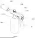


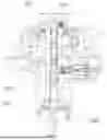
Sources:
- United States Patent and Trademark Office - verify current appl. status at the USPTO↗
Similar patent applications:
- » 20220346216
Wear Part for an Arc Torch and Plasma Torch, Arc Torch and Plasma Torch Comprising Same, Method for Plasma Cutting and Method for Producing an Electrode for an Arc Torch and Plasma Torch - » 20210339331
MIG/MAG welding torch body, TIG welding torch body, MIG/MAG welding torch handle, and MIG/MAG welding torch comprising such a MIG/MAG welding torch body and MIG/MAG welding torch handle - » 20200086414
TIG welding torch body, TIG welding torch handle, and TIG welding torch having such a TIG welding torch body and TIG welding torch handle - » 20160256951
Welding torch system for use in welding or cutting operations, welding torch for use in such a welding torch system and method for welding using such a welding torch system or such a welding torch - » 20150048065
Welding torch with a fixing element for the gas nozzle, said element being capable of extension; process control method for a welding system equipped with said welding torch; gas nozzle for said welding torch; and contact tube for said welding torch - » 20090050609
Welding torch with a fixing element for the gas nozzle, said element being capable of extension; process control method for a welding system equipped with said welding torch; gas nozzle for said welding torch; and contact tube for said welding torch - » 20070000892
Gas nozzle for a welding torch, welding torch, and cleaning device for a welding torch - » 20160120014
Single or multi-part insulating component for a plasma torch, particularly a plasma cutting torch, and assemblies and plasma torches having the same - » 20110011221
Plasma Arc Cutting Torch, Oxygen-Fuel Gas Cutting Torch, Waterjet or Laser Cutting Torch, Pierce Height three or more Multi-Step Transition Height Process control for more than an initial pierce height and set cut height setting - » 20110284502
Nozzle for a liquid-cooled plasma torch, nozzle cap for a liquid-cooled plasma torch and plasma torch head comprising the same
Recent applications in this class:
- » 20250027645 2025-01-23
Lightweight Pressure Reduction Hydrogen Supply Device Suitable for Hydrogen Energy Handheld Torch - » 20240418365 2024-12-19
TORCH ASSEMBLY - » 20240369219 2024-11-07
FLAME TORCH - » 20240344697 2024-10-17
Assembled Long Rod Spray Gun - » 20240125469 2024-04-18
HYDROTORCH ASSEMBLY - » 20230280029 2023-09-07
TORCH HEAD OF BLOWTORCH - » 20230142310 2023-05-11
ROOFING TORCH - » 20220252256 2022-08-11
TORCH EXTENSION - » 20210278079 2021-09-09
Hand torch, base, and regulator system - » 20210247066 2021-08-12
Heat shrink gas gun