ECONOMIZER COOLING TEMPERATURE PROTECTION
US20260063341A1
2026-03-05
19/317,101
2025-09-02
Smart Summary: A cooling system uses a heat exchanger to move heat from a heat source to a cooling fluid. It has a compressor that can compress the vaporized cooling fluid and a condenser that releases heat from the fluid. A pump circulates the cooling fluid through the system. A controller manages the pump's operation based on temperature readings. When temperatures rise, the controller ensures the system cools effectively by adjusting the pump and compressor as needed. 🚀 TL;DR
Abstract:
A cooling loop can include a heat exchanger for transferring heat from a heat source to a cooling fluid, a compressor for selectively compressing a vaporized portion of the cooling fluid, a condenser for rejecting heat from the cooling fluid, a pump for selectively pumping the cooling fluid through the loop, and a controller. The controller can operate the pump to pump the cooling fluid through the loop when the measured temperature is less than a first offset temperature, continue operating the pump to pump the cooling fluid through the loop for a time period when the measured temperature reaches a first offset temperature, and deactivate the pump and initiate operation of the compressor before the measured temperature exceeds a second offset temperature.
Inventors:
- Jeremy Ryan King 8 🇺🇸 Delaware, OH, United States
- GALEN LEWIS GERIG 1 🇺🇸 Columbus, OH, United States
Assignee:
- VERTIV CORPORATION 77 🇺🇸 Westerville, OH, United States
Applicant:
Interested in similar patents?
Get notified when new applications in this technology area are published.
Classification:
F25B41/42 » CPC main
Fluid-circulation arrangements; Fluid line arrangements Arrangements for diverging or converging flows, e.g. branch lines or junctions
Description
CROSS-REFERENCE TO RELATED APPLICATIONS
This application claims the benefit of U.S. Provisional Patent Application No. 63/690,309 filed September 4, 2024, the entire contents of which are incorporated herein by reference.
TECHNICAL FIELD
The present disclosure relates generally to cooling systems used in data centers, and more specifically relates to control of such cooling systems.
BACKGROUND
Cooling systems used in data centers often comprise one or more cooling fluid loops. Some cooling systems utilize a refrigerant as the cooling fluid and a compressor to compress refrigerant that has been vaporized in the extraction of heat. While such compressor driven systems provide significant cooling capacity, they typically have significant power requirements.
Some cooling systems pump the cooling fluid through a cooling loop. Such pumped cooling fluid systems typically have less power requirements, but also have more stringent conditions for application eligibility than compressor driven systems.
Newer cooling systems can utilize a refrigerant as the cooling fluid, a compressor to move the refrigerant through the loop for all cooling demands, and a pump to move the refrigerant through the loop when the conditions are acceptable, thereby providing more economical operation. These systems typically utilize a controller to decide when to utilize the compressor and when to pump the refrigerant through the loop.
SUMMARY
Applicant has created new and useful devices, systems and methods for cooling system control. In at least one embodiment, operating a cooling loop in a pumped refrigerant mode can be more economical, but can involve wider temperature swings, than a compressed refrigerant mode. In at least one embodiment, wider temperature swings can cause a monitored temperature, such as a cooling fluid temperature (in that loop and/or a cascaded loop) to exceed a design limit. In at least one embodiment, a cooling loop can operate in a pumped refrigerant mode or a compressed refrigerant mode, and can switch from the pumped refrigerant mode to the compressed refrigerant mode when a monitored temperature meets or exceeds one offset and a delay time period has elapsed prior to the monitored temperature meeting or exceeding another offset, such as a higher offset. In at least one embodiment, the delay time period can be arranged for increasing system efficiency while nonetheless preventing overheating of a heat source, such as information technology (IT) equipment cooled in a data center.
In at least one embodiment, a cooling loop or system according to the disclosure can include a heat exchanger configured to transfer heat from a heat source to a cooling fluid, a compressor for selectively circulating the cooling fluid through the loop, a condenser configured to reject heat from the cooling fluid, a pump for selectively pumping the cooling fluid through the loop, and one or more controllers operably coupled to the compressor and the pump. In at least one embodiment, the system can monitor a setpoint temperature, a measured temperature, a first time period, a first offset temperature and a second offset temperature, wherein the first offset temperature and the second offset temperature are greater than the setpoint temperature, and wherein the second offset temperature is greater than the first offset temperature. In at least one embodiment, the system can operate the pump to pump the cooling fluid through the loop when the measured temperature is less than the first offset temperature, continue operating the pump to pump the cooling fluid through the loop for the first time period when the measured temperature reaches the first offset temperature, deactivate the pump and initiate operation of the compressor before the measured temperature exceeds the second offset temperature, or any combination thereof. In at least one embodiment, the system can deactivate the pump and initiate operation of the compressor before the measured temperature reaches the second offset temperature.
In at least one embodiment, the system can monitor a second time period and a third offset temperature, wherein the second time period is less than the first time period, and deactivate the pump and initiate operation of the compressor if the measured temperature is greater than or equal to the third offset temperature when the second time period has elapsed. In at least one embodiment, the third offset temperature can be greater than or equal to the second offset temperature. In at least one embodiment, the system can deactivate the pump and initiate operation of the compressor upon conclusion of the first time period, such as regardless of whether the measured temperature is greater than or equal to the first offset temperature when the first time period has elapsed. In at least one embodiment, the first time period can be a predetermined period of time for allowing the measured temperature to exceed the first offset temperature yet preventing the measured temperature from exceeding the second offset temperature.
In at least one embodiment, a method of operating a cooling loop having a compressed refrigerant mode and a pumped refrigerant mode can include monitoring a setpoint temperature, a measured temperature, a first time period, a first offset temperature and a second offset temperature, wherein the first offset temperature and the second offset temperature are greater than the setpoint temperature, and wherein the second offset temperature is greater than the first offset temperature. In at least one embodiment, the method can include operating the loop in the pumped refrigerant mode when the measured temperature is less than the first offset temperature, when the measured temperature reaches the first offset temperature, continuing to operate the loop in the pumped refrigerant mode for the first time period, switching from the pumped refrigerant mode to the compressed refrigerant mode before the measured temperature exceeds the second offset temperature, or any combination thereof. In at least one embodiment, the method can include switching from the pumped refrigerant mode to the compressed refrigerant mode before the measured temperature reaches the second offset temperature.
In at least one embodiment, the method can include monitoring a second time period and a third offset temperature, wherein the second time period is less than the first time period, and switching from the pumped refrigerant mode to the compressed refrigerant mode if the measured temperature is greater than or equal to the third offset temperature when the second time period has elapsed. In at least one embodiment, the third offset temperature can be greater than or equal to the second offset temperature. In at least one embodiment, the method can include switching from the pumped refrigerant mode to the compressed refrigerant mode upon conclusion of the first time period regardless of whether the measured temperature is greater than or equal to the first offset temperature when the first time period has elapsed. In at least one embodiment, the first time period can be a predetermined period of time configured to allow the measured temperature to exceed the first offset temperature and prevent the measured temperature from exceeding the second offset temperature.
In at least one embodiment, a cooling loop according to the disclosure can include a heat exchanger for transferring heat from a heat source to a cooling fluid, a compressor for selectively compressing a vaporized portion of the cooling fluid and/or induce the cooling fluid to flow through the loop, a condenser for rejecting heat from the cooling fluid, a pump for selectively pumping the cooling fluid through the loop, a controller, or any combination thereof. In at least one embodiment, the controller can monitor various sensors, such as one or more temperature sensors, flow sensors, humidity sensors, other sensors, or any combination thereof. In at least one embodiment, the controller can control the compressor, the pump, various valves, fans, or any combination thereof. In at least one embodiment, the valves can include one or more flow control valves, expansion valves, bypass valves, such as to bypass the compressor and/or the pump, or any combination thereof.
In at least one embodiment, the controller can select between the compressor and the pump, such as according to a setpoint and a temperature, operate the pump according to the setpoint and the temperature, switch from the pump to the compressor when the temperature exceeds a threshold, or any combination thereof. In at least one embodiment, the threshold can be greater than the setpoint. In at least one embodiment, the controller can delay switching from the pump to the compressor for a time period, such as a predetermined period of time for preventing a measured temperature from meeting and/or exceeding an offset temperature. In at least one embodiment, the controller can switch from the pump to the compressor when the temperature meets or exceeds the threshold after a delay period has expired. In at least one embodiment, the controller can switch from the pump to the compressor when the temperature meets or exceeds the threshold for a predetermined period of time.
In at least one embodiment, the controller can select between the compressor and the pump, such as according to a setpoint and a temperature, operate the compressor according to a first offset, operate the pump according to a second offset, switch from the pump to the compressor when the temperature exceeds a threshold, or any combination thereof. In at least one embodiment, the controller can select between the compressor and the pump according to a cooling demand signal, operate the compressor according to a first offset, operate the pump according to a second offset, switch from the pump to the compressor when a temperature exceeds a threshold, or any combination thereof. In at least one embodiment, the controller can operate the compressor and/or the pump according to the various offsets with respect to the setpoint, the cooling demand signal, the temperature, which can be indicated by one or more of the temperature sensors, or any combination thereof. In at least one embodiment, the second offset can be greater than the first offset, such as to allow for a greater variation in the temperature when the pump is operating. In at least one embodiment, the threshold can be greater than the setpoint, the first offset from the setpoint, the second offset from the setpoint, or any combination thereof.
In at least one embodiment, the controller can delay switching from the pump to the compressor for a predetermined period of time after switching from the compressor to the pump, such as to prevent frequent switching between the compressor and the pump. In at least one embodiment, the controller can switch from the pump to the compressor when the temperature exceeds the threshold after a delay period has expired and/or when the temperature exceeds the threshold for a predetermined period of time.
In at least one embodiment, operating the compressor can include bypassing the pump and/or varying a speed of the compressor to maintain the temperature within one or more offsets, ranges, or settings. In at least one embodiment, operating the pump can include bypassing the compressor and/or varying a speed of the pump to maintain the temperature within one or more offsets, ranges, or settings.
In at least one embodiment, the controller can operate the compressor according to one temperature range setting, operate the pump according to another temperature range setting, switch from the pump to the compressor when a monitored temperature exceeds a limit, or any combination thereof. In at least one embodiment, the controller can operate the compressor according to one temperature range setting, operate the pump according to another temperature range setting, switch from the pump to the compressor when a cooling demand signal exceeds a threshold, or any combination thereof. In at least one embodiment, one temperature range setting can be wider than another temperature range setting. In at least one embodiment, the threshold and/or the limit can be outside one temperature range or setting and inside another temperature range or setting.
In at least one embodiment, the controller can delay switching from the pump to the compressor for a predetermined period of time. In at least one embodiment, the predetermined period of time can be a period of time for preventing a measured temperature from meeting and/or exceeding an offset temperature. In at least one embodiment, the predetermined period of time can be measured from when the temperature exceeds the limit, such that switching from the pump to the compressor occurs after the temperature exceeds the limit for the predetermined period of time. In at least one embodiment, the predetermined period of time can be measured from when the cooling demand signal drops below or rises above the threshold.
In at least one embodiment, a method according to the disclosure can be used for operating a cooling loop having a compressed refrigerant mode and a pumped refrigerant mode. In at least one embodiment, a method according to the disclosure can include operating the loop in the compressed refrigerant mode when a cooling demand is greater than a threshold, operating the loop in the pumped refrigerant mode when the cooling demand is less than the threshold, switching from the pumped refrigerant mode to the compressed refrigerant mode when a temperature exceeds a limit, or any combination thereof. In at least one embodiment, operating the loop in the compressed refrigerant mode can include allowing the temperature to vary within a first range. In at least one embodiment, operating the loop in the pumped refrigerant mode can include allowing the temperature to vary within a second range. In at least one embodiment, the second range can be wider than the first range. In at least one embodiment, the limit can be within or outside the second range and/or within or outside the first range.
In at least one embodiment, the method according to the disclosure can include delaying switching from the pumped refrigerant mode to the compressed refrigerant mode, such as to prevent frequent switching between the compressed refrigerant mode and the pumped refrigerant mode. In at least one embodiment, the method according to the disclosure can include delaying switching back to the pumped refrigerant mode from the compressed refrigerant mode for a delay period, even when the cooling demand is less than the threshold, such as to prevent frequent switching between the compressed refrigerant mode and the pumped refrigerant mode.
In at least one embodiment, switching from the pumped refrigerant mode to the compressed refrigerant mode can include switching from the pumped refrigerant mode to the compressed refrigerant mode when the temperature exceeds the limit after a delay period has expired. In at least one embodiment, the delay period can be measured from the temperature exceeding the limit. In at least one embodiment, switching from the pumped refrigerant mode to the compressed refrigerant mode can include switching from the pumped refrigerant mode to the compressed refrigerant mode when the temperature meets or exceeds the limit and a predetermined period of time has elapsed.
In at least one embodiment, switching from the pumped refrigerant mode to the compressed refrigerant mode can include switching from the pumped refrigerant mode to the compressed refrigerant mode when the temperature exceeds the limit independently and/or regardless of the cooling demand. In at least one embodiment, switching from the pumped refrigerant mode to the compressed refrigerant mode can include switching from the pumped refrigerant mode to the compressed refrigerant mode when the temperature exceeds the limit, even if the cooling demand is below the threshold.
In at least one embodiment, a compressor mode can be pulled in or activated sooner than it would have otherwise because a pump mode is drifting outside of one or more limits, which can be or include any limit(s) required or desired in accordance with an implementation of the disclosure. In at least one embodiment, a compressor mode can operate at a larger range than a pump mode in at least one or more ways. In at least one embodiment, a compressor mode can operate at a smaller range than a pump mode in at least one or more ways. In at least one embodiment a compressor mode can hold operation tighter than a pump mode allows.
BRIEF DESCRIPTION OF THE DRAWINGS
FIG. 1 is a simplified diagram of one of many embodiments of a cooling loop according to the disclosure.
FIG. 2 is a simplified diagram of another one of many embodiments of a cooling loop according to the disclosure.
FIG. 3 is a simplified diagram of one of many embodiments of a cascaded loop that can be used in conjunction with a cooling loop according to the disclosure.
FIG. 4 is a simplified control routine for one of many embodiments of a cooling loop according to the disclosure.
FIG. 5 is an exemplary plot of system temperatures over time for one of many embodiments of a cooling loop according to the disclosure.
FIG. 6 is an exemplary plot of power usage over time for the embodiment of FIG. 5.
FIG. 7 is another simplified control routine for one of many embodiments of a cooling loop according to the disclosure.
FIG. 8 is yet another simplified control routine for one of many embodiments of a cooling loop according to the disclosure.
DETAILED DESCRIPTION
The figures described above and the written description of specific structures and functions below are not presented to limit the scope of what Applicant has invented or the scope of the appended claims. Rather, the figures and written description are provided to teach any person skilled in the art to make and use the inventions for which patent protection is sought. Those skilled in the art will appreciate that not all features of a commercial embodiment of the inventions are described or shown for the sake of clarity and understanding. Persons of skill in this art will also appreciate that the development of an actual commercial embodiment incorporating aspects of the present inventions will require numerous implementation-specific decisions to achieve the developer’s ultimate goal for the commercial embodiment. Such implementation-specific decisions may include, and likely are not limited to, compliance with system-related, business-related, government-related and other constraints, which may vary by specific implementation, location and from time to time. While a developer’s efforts might be complex and time-consuming in an absolute sense, such efforts would be, nevertheless, a routine undertaking for those of skill in this art having benefit of this disclosure. It must be understood that the inventions disclosed and taught herein are susceptible to numerous and various modifications and alternative forms.
The use of a singular term, such as, but not limited to, “a,” is not intended as limiting of the number of items. Also, the use of relational terms, such as, but not limited to, “top,” “bottom,” “left,” “right,” “upper,” “lower,” “down,” “up,” “side,” and the like are used in the written description for clarity in specific reference to the figures and are not intended to limit the scope of the inventions or the appended claims. The terms “including” and “such as” are illustrative and not limitative. The terms “couple,” “coupled,” “coupling,” “coupler,” and like terms are used broadly herein and can include any method or device for securing, binding, bonding, fastening, attaching, joining, inserting therein, forming thereon or therein, communicating, or otherwise associating, for example, mechanically, magnetically, electrically, chemically, operably, directly or indirectly with intermediate elements, one or more pieces of members together and can further include without limitation integrally forming one functional member with another in a unity fashion. The coupling can occur in any direction, including rotationally. Further, all parts and components of the disclosure that are capable of being physically embodied inherently include imaginary and real characteristics regardless of whether such characteristics are expressly described herein, including but not limited to characteristics such as axes, ends, inner and outer surfaces, interior spaces, tops, bottoms, sides, boundaries, dimensions (e.g., height, length, width, thickness), mass, weight, volume and density, among others.
Any process flowcharts discussed herein illustrate the operation of possible implementations of systems, methods, and computer program products according to various embodiments of the present disclosure. In this regard, each block in a flowchart may represent a module, segment, or portion of code, which can comprise one or more executable instructions for implementing the specified logical function(s). It should also be noted that, in some implementations, the function(s) noted in the block(s) might occur out of the order depicted in the figures. For example, blocks shown in succession may, in fact, be executed substantially concurrently. It will also be noted that each block of flowchart illustration can be implemented by special purpose hardware-based systems that perform the specified functions or acts, or combinations of special purpose hardware and computer instructions.
Applicant has created new and useful devices, systems and methods for cooling system control. In at least one embodiment, operating a cooling loop in a pumped refrigerant mode can be more economical, but can involve wider temperature swings, than a compressed refrigerant mode. In at least one embodiment, wider temperature swings can cause a monitored temperature, such as a cooling fluid temperature (in that loop and/or a cascaded loop) to exceed a design limit. In at least one embodiment, a cooling loop can operate in a compressed refrigerant mode when cooling demand is high and a pumped refrigerant mode when cooling demand is low and switch from the pumped refrigerant mode to the compressed refrigerant mode when a monitored temperature exceeds a design limit, regardless of the cooling demand. In at least one embodiment, a cooling loop can delay such a switch for a period of time, such as to avoid frequent switching between the pumped refrigerant mode and the compressed refrigerant mode and/or increase system efficiency while nonetheless protecting against overheating of the heat source (e.g., information technology (IT) equipment).
FIG. 1 is a simplified diagram of one of many embodiments of a cooling loop according to the disclosure. FIG. 2 is a simplified diagram of another one of many embodiments of a cooling loop according to the disclosure. FIG. 3 is a simplified diagram of one of many embodiments of a cascaded loop that can be used in conjunction with a cooling loop according to the disclosure. FIG. 4 is a simplified control routine for one of many embodiments of a cooling loop according to the disclosure. FIG. 5 is an exemplary plot of system temperatures over time for one of many embodiments of a cooling loop according to the disclosure. FIG. 6 is an exemplary plot of power usage over time for the embodiment of FIG. 5. FIG. 7 is another simplified control routine for one of many embodiments of a cooling loop according to the disclosure. FIG. 8 is yet another simplified control routine for one of many embodiments of a cooling loop according to the disclosure. FIGS. 1-8 are described in conjunction with one another.
In at least one embodiment, a cooling loop 100 according to the disclosure can include one or more heat exchanger 110 for transferring heat from one or more heat sources (such as a heat load or a cascaded loop 200) to a cooling fluid, one or more compressors 120 for selectively compressing a vaporized portion of the cooling fluid and/or induce the cooling fluid to flow through the loop 100, one or more condensers 130 for rejecting heat from the cooling fluid, one or more pumps 140 for selectively pumping the cooling fluid through the loop 100, one or more controllers 150, or any combination thereof. In at least one embodiment, the controller 150 can monitor one or more sensors 160, such as one or more temperature sensors, flow sensors, humidity sensors, other sensors, or any combination thereof with respect to the loop 100 and/or the cascaded loop 200. In at least one embodiment, the controller 150 can control the compressor(s) 120, the pump(s) 140, one or more valves 170, one or more fans, or any combination thereof, such as in an effort to control one or more temperatures associated with the loop 100 and/or the cascaded loop 200. In at least one embodiment, the valves 170 can include one or more flow control valves, one or more expansion valves, one or more bypass valves, such as to bypass the compressor 120 and/or the pump 140, or any combination thereof. In at least one embodiment, the controller 150 can communicate with one or more supervisory systems and/or one or more users through one or more user interfaces 180. In at least one embodiment, the cooling fluid circulating in the loop 100 can be a two-phase refrigerant.
In at least one embodiment, the controller 150 can select between the compressor 120 and the pump 140, such as according to a setpoint and a temperature, operate the pump 140 according to the setpoint and the temperature, switch from the pump 140 to the compressor 120 when the temperature exceeds a threshold, or any combination thereof. In at least one embodiment, the threshold can be greater than the setpoint. For example, in at least one embodiment, the setpoint can be 76 degrees Fahrenheit and/or the threshold can be 76.3 degrees Fahrenheit (provided, however, that this is but one example of many, and the setpoint, the threshold, and any other temperatures and/or temperature settings can be or include any temperature(s) required or desired according to an implementation of the disclosure). In at least one embodiment, the controller 150 can delay switching from the pump 140 to the compressor 120 for a predetermined period of time, which can be measured, for example, from the time of a preceding switch in operation from the compressor 120 to the pump 140. In at least one embodiment, the controller 150 can switch from the pump 140 to the compressor 120 when the temperature exceeds the threshold after a delay period has expired. In at least one embodiment, the controller 150 can switch from the pump 140 to the compressor 120 when the temperature exceeds the threshold for a predetermined period of time. In at least one embodiment, the predetermined period of time, or delay, can be 9 seconds. In at least one embodiment, the controller 150 can switch from the pump 140 to the compressor 120 when the temperature exceeds 76.3 degrees Fahrenheit for 9 seconds and/or the controller 150 can switch from the pump 140 to the compressor 120 9 seconds after the temperature exceeds 76.3 degrees Fahrenheit (see, e.g., FIGS. 5-6). Of course, the foregoing temperatures and time periods are but some examples of many and are included herein merely for purposes of illustration, not limitation. The time periods, temperatures and/or temperature settings can be or include any time period(s) and/or temperature(s) required or desired according to an implementation of the disclosure.
In at least one embodiment, the controller 150 can select between the compressor 120 and the pump 140, such as according to one or more cooling demand signals, one or more setpoints, one or more temperatures, or any combination thereof. In at least one embodiment, the controller 150 can operate the compressor 120 according to a first offset, operate the pump 140 according to a second offset, switch from the pump 140 to the compressor 120 when the temperature(s) exceed one or more thresholds, or any combination thereof. In at least one embodiment, the controller 150 can operate the compressor 120 and/or the pump 140 according to the various offsets with respect to the setpoint, the cooling demand signal, the temperature, which can be indicated by one or more of the temperature sensors 160, or any combination thereof. In at least one embodiment, the second offset can be greater than the first offset, such as to allow for a greater variation in the temperature when the pump 140 is operating. In at least one embodiment, the threshold can be greater than the setpoint, the first offset from the setpoint, the second offset from the setpoint, or any combination thereof. In at least one embodiment, the threshold can be greater than the setpoint and the first offset from the setpoint, but less than the second offset from the setpoint. In at least one embodiment, the threshold can be independent from the setpoint, the first offset from the setpoint, the second offset from the setpoint, or any combination thereof.
In at least one embodiment, the controller 150 can delay switching from the pump 140 to the compressor 120 for a predetermined period of time after switching from the compressor 120 to the pump 140, such as to prevent frequent switching between the compressor 120 and the pump 140. In at least one embodiment, the controller 150 can switch from the pump 140 to the compressor 120 when the temperature exceeds the threshold after a delay period has expired and/or when the temperature exceeds the threshold for a predetermined period of time.
In at least one embodiment, operating the compressor 120 can include bypassing the pump 140 and/or varying a speed of the compressor 120 to maintain the temperature within one or more offsets, ranges, or settings. In at least one embodiment, the loop 100 can include a pump check valve 142 for bypassing the pump 140, such as when the compressor 120 is operating. In at least one embodiment, operating the pump 140 can include bypassing the compressor 120 and/or varying a speed of the pump 140 to maintain the temperature within one or more offsets, ranges, or settings. In at least one embodiment, the loop 100 can include a compressor check valve 122 for bypassing the compressor 120, such as when the pump 140 is operating.
In at least one embodiment, the controller 150 can operate the compressor 120 according to a temperature range setting, operate the pump 140 according to another temperature range setting, switch from the pump 140 to the compressor 120 when a monitored temperature exceeds a limit, or any combination thereof. In at least one embodiment, the controller 150 can operate the compressor 120 according to a temperature range setting, operate the pump 140 according to another temperature range setting, switch from the pump 140 to the compressor 120 when a cooling demand signal exceeds a threshold, switch from the compressor 120 to the pump 140 when a cooling demand signal is below the threshold, or any combination thereof. In at least one embodiment, one temperature range setting can be wider than another temperature range setting. In at least one embodiment, the threshold and/or the limit can be outside one temperature range or setting and inside another temperature range or setting. In at least one embodiment, the threshold and/or the limit can be outside two or more temperature ranges or settings.
In at least one embodiment, the controller 150 can delay switching from the pump 140 to the compressor 120 for a predetermined period of time. In at least one embodiment, the predetermined period of time can be a period of time for preventing a measured temperature from meeting and/or exceeding an offset temperature, such as an offset temperature specified by a data center customer or other user. In at least one embodiment, the predetermined period of time can be measured from when the temperature exceeds the limit, and switching from the pump 140 to the compressor 120 can occur or be initiated after the temperature exceeds the limit and/or after the predetermined period of time has elapsed. In at least one embodiment, the predetermined period of time can be measured from when the cooling demand signal drops below or rises above the threshold. In at least one embodiment, the predetermined period of time can be a period of time specified, for example, by a data center customer, and in any event the predetermined period of time can be any period of time required or desired according to an implementation of the disclosure.
In at least one embodiment, the cascaded loop 200 can include one or more pumps 240 for circulating another cooling fluid through the cascaded loop 200. In at least one embodiment, the cooling fluid circulating in the cascaded loop 200 can be a two-phase refrigerant or a single-phase refrigerant, such as water or a water-glycol mix. In at least one embodiment, the cascaded loop 200 can extract heat from one or more heat sources (such as one or more servers or other heat loads) and transfer that heat to the loop 100 through the heat exchanger 110. In at least one embodiment, the cascaded loop 200 can include one or more valves 270, such as a three-way valve 270 to control or throttle how much of the cooling fluid circulating in the cascaded loop 200 flow through the heat exchanger 110 and/or how much of the cooling fluid circulating in the cascaded loop 200 bypasses the heat exchanger 110. In at least one embodiment, the cascaded loop 200 can include one or more sensors 160, such as those discussed above. In at least one embodiment, the controller 150 can control the pump(s) 240 and/or the valve(s) 270, and monitor the sensor(s) 160 of the cascaded loop 200.
In at least one embodiment, a method according to the disclosure can be used for operating a cooling loop 100 having a compressed refrigerant mode and a pumped refrigerant mode. In at least one embodiment, a method according to the disclosure can include operating the loop 100 in the compressed refrigerant mode when a cooling demand is greater than a threshold, operating the loop 100 in the pumped refrigerant mode when the cooling demand is less than the threshold, switching from the pumped refrigerant mode to the compressed refrigerant mode when a temperature exceeds a limit, or any combination thereof. In at least one embodiment, operating the loop 100 in the compressed refrigerant mode can include allowing the temperature to vary within a first range. In at least one embodiment, operating the loop 100 in the pumped refrigerant mode can include allowing the temperature to vary within a second range. In at least one embodiment, the second range can be wider than the first range. In at least one embodiment, the limit can be within or outside the second range and/or within or outside the first range.
In at least one embodiment, the method according to the disclosure can include delaying switching from the pumped refrigerant mode to the compressed refrigerant mode, such as to prevent frequent switching between the compressed refrigerant mode and the pumped refrigerant mode. In at least one embodiment, the method according to the disclosure can include delaying switching back to the pumped refrigerant mode from the compressed refrigerant mode for a delay period, such as to prevent frequent switching between the compressed refrigerant mode and the pumped refrigerant. In at least one embodiment, the method according to the disclosure can include delaying switching back to the pumped refrigerant mode from the compressed refrigerant mode for a delay period, even when the cooling demand is less than the threshold, such as to prevent frequent switching between the compressed refrigerant mode and the pumped refrigerant.
In at least one embodiment, switching from the pumped refrigerant mode to the compressed refrigerant mode can include switching from the pumped refrigerant mode to the compressed refrigerant mode when the temperature exceeds the limit after a delay period has expired. In at least one embodiment, the delay period can be measured from the temperature exceeding the limit. In at least one embodiment, switching from the pumped refrigerant mode to the compressed refrigerant mode can include switching from the pumped refrigerant mode to the compressed refrigerant mode when the temperature exceeds the limit for a predetermined period of time. In at least one embodiment, a pumped refrigerant mode can be or include operating a pump to pump cooling fluid through a cooling loop, such as when pumped refrigerant economizer (PRE) operation provides adequate cooling capacity for a given implementation of the disclosure. In at least one embodiment, a compressed refrigerant mode can be or include operating a compressor to compress a vaporized portion of the cooling fluid and circulate the cooling fluid through the loop, such as when direct expansion (DX) operation may be required or desired for providing adequate cooling capacity in a given implementation of the disclosure.
In at least one embodiment, switching from the pumped refrigerant mode to the compressed refrigerant mode can include switching from the pumped refrigerant mode to the compressed refrigerant mode when the temperature exceeds the limit independently and/or regardless of the cooling demand. In at least one embodiment, switching from the pumped refrigerant mode to the compressed refrigerant mode can include switching from the pumped refrigerant mode to the compressed refrigerant mode when the temperature exceeds the limit, even if the cooling demand is below the threshold. In at least one embodiment, the controller 150 can select between the compressed refrigerant mode and the pumped refrigerant mode according to a cooling demand signal and switch from the pumped refrigerant mode to the compressed refrigerant mode when a temperature, such as a fluid temperature in the cascaded loop 200, exceeds a limit, exceeds a limit for a period of time, or exceeds a limit after a delay period has expired.
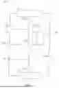
In at least one embodiment, the controller 150 can utilize a control method or routine 300, 400, 500 to ensure that a temperature does not exceed a limit for a period of time. In at least one embodiment, a control routine 300 according to the disclosure can include monitoring a temperature, such as a supply water temperature or Supply Water Measurement (SWM), as shown in step 310. In at least one embodiment, the control routine 300 can include calculating an upper limit temperature, such as be adding a Supply Water Setpoint (SWS) and an Excursion Upper Limit (EUL), as shown in step 316. In at least one embodiment, the control routine 300 can include detecting if or when the temperature, such as the SWM, exceeds the upper limit temperature or a setpoint plus an offset, such as the EUL, as shown in step 320. In at least one embodiment, the control routine 300 can include running a timer (T), as shown in step 324, and/or recognizing an Excursion Duration (ED), as shown in step 326. In at least one embodiment, the control routine 300 can include detecting if or when the temperature exceeds the setpoint plus the offset for a predetermined period of time, as shown in step 330. In at least one embodiment, the control routine 300 can include switching from pumped refrigerant mode to the compressed refrigerant mode, as shown in step 340, if or when the temperature exceeds the setpoint plus the offset for the predetermined period of time. In at least one embodiment, if the temperature, such as the SWM, does not exceed the upper limit temperature (or a setpoint plus an offset, such as the EUL), as shown in step 350, the control routine 300 can include resetting the timer, as shown in step 360, and/or remaining in the pumped refrigerant economizer (PRE) mode, as shown in step 370.
In at least one embodiment, the controller 150 can utilize a sensor 160, such as in the cascaded loop 200, to monitor and/or control the supply water temperature or take the SWM. In at least one embodiment, the SWS can be 74 degrees Fahrenheit, the ED can be 10 minutes, the EUL can be 2 degrees Fahrenheit, or any combination thereof. In at least one embodiment, the SWS can be between 72 and 76 degrees Fahrenheit, between 70 and 80 degrees Fahrenheit, or between 65 and 85 degrees Fahrenheit. In at least one embodiment, the ED can be between 7 and 12 minutes, between 5 and 15 minutes, or between 2 and 20 minutes. In at least one embodiment, the EUL can be 3 degrees Fahrenheit, 5 degrees Fahrenheit, or 10 degrees Fahrenheit.
In at least one embodiment, a control routine 400 according to the disclosure can include switching from the direct expansion (DX) mode, in which the pump 140 can be bypassed and the compressor 120 can be used, to the pumped refrigerant economizer (PRE) mode, in which the pump 140 can be used and the compressor 120 can be bypassed, as shown in step 410. In at least one embodiment, the control routine 400 can proceed to any or all of steps 310, 316, 320, 324326, 330, 340, 35, 360, 370, or any combination thereof of the control routine 300. In at least one embodiment, a control routine 500 according to the disclosure can include switching from the DX mode to the PRE mode, as shown in step 510, and waiting for a time delay to expire, as shown in step 520, before proceeding to any or all of steps 310, 316, 320, 324326, 330, 340, 35, 360, 370, or any combination thereof of the control routine 300. It can be seen that the control routine 400 can switch from the pumped refrigerant economizer (PRE) mode to the direct expansion (DX) mode faster than the control routine 500. It can also be seen that the control routine 500 can minimize switching back and forth between the pumped refrigerant economizer (PRE) mode and the direct expansion (DX) mode.
In at least one embodiment, a cooling loop or system according to the disclosure can include a heat exchanger configured to transfer heat from a heat source to a cooling fluid, a compressor for selectively circulating the cooling fluid through the loop, a condenser configured to reject heat from the cooling fluid, a pump for selectively pumping the cooling fluid through the loop, and one or more controllers operably coupled to the compressor and the pump. In at least one embodiment, the system can monitor a setpoint temperature, a measured temperature, a first time period, a first offset temperature and a second offset temperature, wherein the first offset temperature and the second offset temperature are greater than the setpoint temperature, and wherein the second offset temperature is greater than the first offset temperature. In at least one embodiment, the system can operate the pump to pump the cooling fluid through the loop when the measured temperature is less than the first offset temperature, continue operating the pump to pump the cooling fluid through the loop for the first time period when the measured temperature reaches the first offset temperature, deactivate the pump and initiate operation of the compressor before the measured temperature exceeds the second offset temperature, or any combination thereof. In at least one embodiment, the system can deactivate the pump and initiate operation of the compressor before the measured temperature reaches the second offset temperature.
In at least one embodiment, the system can monitor a second time period and a third offset temperature, wherein the second time period is less than the first time period, and deactivate the pump and initiate operation of the compressor if the measured temperature is greater than or equal to the third offset temperature when the second time period has elapsed. In at least one embodiment, the third offset temperature can be greater than or equal to the second offset temperature. In at least one embodiment, the system can deactivate the pump and initiate operation of the compressor upon conclusion of the first time period, such as regardless of whether the measured temperature is greater than or equal to the first offset temperature when the first time period has elapsed. In at least one embodiment, the first time period can be a predetermined period of time for allowing the measured temperature to exceed the first offset temperature yet preventing the measured temperature from exceeding the second offset temperature.
In at least one embodiment, a method of operating a cooling loop having a compressed refrigerant mode and a pumped refrigerant mode can include monitoring a setpoint temperature, a measured temperature, a first time period, a first offset temperature and a second offset temperature, wherein the first offset temperature and the second offset temperature are greater than the setpoint temperature, and wherein the second offset temperature is greater than the first offset temperature. In at least one embodiment, the method can include operating the loop in the pumped refrigerant mode when the measured temperature is less than the first offset temperature, when the measured temperature reaches the first offset temperature, continuing to operate the loop in the pumped refrigerant mode for the first time period, switching from the pumped refrigerant mode to the compressed refrigerant mode before the measured temperature exceeds the second offset temperature, or any combination thereof. In at least one embodiment, the method can include switching from the pumped refrigerant mode to the compressed refrigerant mode before the measured temperature reaches the second offset temperature.
In at least one embodiment, the method can include monitoring a second time period and a third offset temperature, wherein the second time period is less than the first time period, and switching from the pumped refrigerant mode to the compressed refrigerant mode if the measured temperature is greater than or equal to the third offset temperature when the second time period has elapsed. In at least one embodiment, the third offset temperature can be greater than or equal to the second offset temperature. In at least one embodiment, the method can include switching from the pumped refrigerant mode to the compressed refrigerant mode upon conclusion of the first time period regardless of whether the measured temperature is greater than or equal to the first offset temperature when the first time period has elapsed. In at least one embodiment, the first time period can be a predetermined period of time configured to allow the measured temperature to exceed the first offset temperature and prevent the measured temperature from exceeding the second offset temperature.
In at least one embodiment, the controller can select between the compressor and the pump, such as according to a setpoint and a temperature, operate the pump according to the setpoint and the temperature, switch from the pump to the compressor when the temperature exceeds a threshold, or any combination thereof. In at least one embodiment, the threshold can be greater than the setpoint. In at least one embodiment, the controller can delay switching from the pump to the compressor for a time period, such as a predetermined period of time for preventing a measured temperature from meeting and/or exceeding an offset temperature. In at least one embodiment, the controller can switch from the pump to the compressor when the temperature meets or exceeds the threshold after a delay period has expired. In at least one embodiment, the controller can switch from the pump to the compressor when the temperature meets or exceeds the threshold for a predetermined period of time.
In at least one embodiment, a cooling loop according to the disclosure can include a heat exchanger for transferring heat from a heat source to a cooling fluid, a compressor for selectively compressing a vaporized portion of the cooling fluid and/or induce the cooling fluid to flow through the loop, a condenser for rejecting heat from the cooling fluid, a pump for selectively pumping the cooling fluid through the loop, a controller, or any combination thereof. In at least one embodiment, the controller can monitor various sensors, such as one or more temperature sensors, flow sensors, humidity sensors, other sensors, or any combination thereof. In at least one embodiment, the controller can control the compressor, the pump, various valves, fans, or any combination thereof. In at least one embodiment, the valves can include one or more flow control valves, expansion valves, bypass valves, such as to bypass the compressor and/or the pump, or any combination thereof.
In at least one embodiment, the controller can select between the compressor and the pump, such as according to a setpoint and a temperature, operate the compressor according to a first offset, operate the pump according to a second offset, switch from the pump to the compressor when the temperature exceeds a threshold, or any combination thereof. In at least one embodiment, the controller can select between the compressor and the pump according to a cooling demand signal, operate the compressor according to a first offset, operate the pump according to a second offset, switch from the pump to the compressor when a temperature exceeds a threshold, or any combination thereof. In at least one embodiment, the controller can operate the compressor and/or the pump according to the various offsets with respect to the setpoint, the cooling demand signal, the temperature, which can be indicated by one or more of the temperature sensors, or any combination thereof. In at least one embodiment, the second offset can be greater than the first offset, such as to allow for a greater variation in the temperature when the pump is operating. In at least one embodiment, the threshold can be greater than the setpoint, the first offset from the setpoint, the second offset from the setpoint, or any combination thereof.
In at least one embodiment, the controller can delay switching from the pump to the compressor for a predetermined period of time after switching from the compressor to the pump, such as to prevent frequent switching between the compressor and the pump. In at least one embodiment, the controller can switch from the pump to the compressor when the temperature exceeds the threshold after a delay period has expired and/or when the temperature exceeds the threshold for a predetermined period of time.
In at least one embodiment, operating the compressor can include bypassing the pump and/or varying a speed of the compressor to maintain the temperature within one or more offsets, ranges, or settings. In at least one embodiment, operating the pump can include bypassing the compressor and/or varying a speed of the pump to maintain the temperature within one or more offsets, ranges, or settings.
In at least one embodiment, the controller can operate the compressor according to one temperature range setting, operate the pump according to another temperature range setting, switch from the pump to the compressor when a monitored temperature exceeds a limit, or any combination thereof. In at least one embodiment, the controller can operate the compressor according to one temperature range setting, operate the pump according to another temperature range setting, switch from the pump to the compressor when a cooling demand signal exceeds a threshold, or any combination thereof. In at least one embodiment, one temperature range setting can be wider than another temperature range setting. In at least one embodiment, the threshold and/or the limit can be outside one temperature range or setting and inside another temperature range or setting. In at least one embodiment, the threshold and/or the limit can be outside two or more temperature ranges or settings.
In at least one embodiment, the controller can delay switching from the pump to the compressor for a predetermined period of time. In at least one embodiment, the predetermined period of time can be a period of time for preventing a measured temperature from meeting and/or exceeding an offset temperature. In at least one embodiment, the predetermined period of time can be measured from when the temperature exceeds the limit, such that switching from the pump to the compressor occurs after the temperature meets or exceeds the limit and/or after the predetermined period of time has elapsed. In at least one embodiment, the predetermined period of time can be measured from when the cooling demand signal drops below or rises above the threshold.
In at least one embodiment, a method according to the disclosure can be used for operating a cooling loop having a compressed refrigerant mode and a pum0ped refrigerant mode. In at least one embodiment, a method according to the disclosure can include operating the loop in the compressed refrigerant mode when a cooling demand is greater than a threshold, operating the loop in the pumped refrigerant mode when the cooling demand is less than the threshold, switching from the pumped refrigerant mode to the compressed refrigerant mode when a temperature exceeds a limit, or any combination thereof. In at least one embodiment, operating the loop in the compressed refrigerant mode can include allowing the temperature to vary within a first range. In at least one embodiment, operating the loop in the pumped refrigerant mode can include allowing the temperature to vary within a second range. In at least one embodiment, the second range can be wider than the first range. In at least one embodiment, the limit can be within or outside the second range and/or within or outside the first range.
In at least one embodiment, the method according to the disclosure can include delaying switching from the pumped refrigerant mode to the compressed refrigerant mode, such as to prevent frequent switching between the compressed refrigerant mode and the pumped refrigerant mode. In at least one embodiment, the method according to the disclosure can include delaying switching back to the pumped refrigerant mode from the compressed refrigerant mode for a delay period, even when the cooling demand is less than the threshold, such as to prevent frequent switching between the compressed refrigerant mode and the pumped refrigerant.
In at least one embodiment, switching from the pumped refrigerant mode to the compressed refrigerant mode can include switching from the pumped refrigerant mode to the compressed refrigerant mode when the temperature meets or exceeds the limit and a delay period has expired. In at least one embodiment, the delay period can be measured from the temperature meeting or exceeding the limit. In at least one embodiment, switching from the pumped refrigerant mode to the compressed refrigerant mode can include switching from the pumped refrigerant mode to the compressed refrigerant mode when the temperature exceeds the limit and/or a predetermined period of time has elapsed. In at least one embodiment, implementing one or more control routines for determining whether and/or when to switch from the pumped refrigerant mode to the compressed refrigerant mode can include waiting for a time delay counter to expire following a preceding switch from the compressed refrigerant mode to the pumped refrigerant mode.
In at least one embodiment, switching from the pumped refrigerant mode to the compressed refrigerant mode can include switching from the pumped refrigerant mode to the compressed refrigerant mode when the temperature exceeds the limit independently and/or regardless of the cooling demand. In at least one embodiment, switching from the pumped refrigerant mode to the compressed refrigerant mode can include switching from the pumped refrigerant mode to the compressed refrigerant mode when the temperature exceeds the limit, even if the cooling demand is below the threshold.
In at least one embodiment, a compressor mode can be pulled in or activated sooner than it would have otherwise because a pump mode is drifting outside of one or more limits, which can be or include any limit(s) required or desired in accordance with an implementation of the disclosure. In at least one embodiment, a compressor mode can operate at a larger range than a pump mode in at least one or more ways. In at least one embodiment, a compressor mode can operate at a smaller range than a pump mode in at least one or more ways. In at least one embodiment a compressor mode can hold operation tighter than a pump mode allows.
Other and further embodiments utilizing one or more aspects of the disclosure can be devised without departing from the spirit of Applicant’s disclosure. For example, the devices, systems and methods can be implemented for numerous different types and sizes in numerous different industries. Further, the various methods and embodiments of the devices, systems and methods can be included in combination with each other to produce variations of the disclosed methods and embodiments. Discussion of singular elements can include plural elements and vice versa. The order of steps can occur in a variety of sequences unless otherwise specifically limited. The various steps described herein can be combined with other steps, interlineated with the stated steps, and/or split into multiple steps. Similarly, elements have been described functionally and can be embodied as separate components or can be combined into components having multiple functions.
The inventions have been described in the context of preferred and other embodiments and not every embodiment of the inventions has been described. Obvious modifications and alterations to the described embodiments are available to those of ordinary skill in the art having the benefits of the present disclosure. The disclosed and undisclosed embodiments are not intended to limit or restrict the scope or applicability of the inventions conceived of by the Applicant, but rather, in conformity with the patent laws, Applicant intends to fully protect all such modifications and improvements that come within the scope or range of equivalents of the following claims.
Claims
What is claimed is:1. A cooling loop comprising:
a heat exchanger configured to transfer heat from a heat source to a cooling fluid;
a compressor configured to selectively compress a vaporized portion of the cooling fluid and circulate the cooling fluid through the loop;
a condenser configured to reject heat from the cooling fluid;
a pump configured to selectively pump the cooling fluid through the loop; and
a controller configured to:
monitor a setpoint temperature, a measured temperature, a first time period, a first offset temperature and a second offset temperature, wherein the first offset temperature and the second offset temperature are greater than the setpoint temperature, and wherein the second offset temperature is greater than the first offset temperature;
operate the pump to pump the cooling fluid through the loop when the measured temperature is less than the first offset temperature;
when the measured temperature reaches the first offset temperature, continue operating the pump to pump the cooling fluid through the loop for the first time period; and
deactivate the pump and initiate operation of the compressor before the measured temperature exceeds the second offset temperature.
2. The cooling loop as set forth in claim 1, wherein the controller is further configured to deactivate the pump and initiate operation of the compressor before the measured temperature reaches the second offset temperature.
3. The cooling loop as set forth in claim 1, wherein the controller is further configured to monitor a second time period and a third offset temperature, wherein the second time period is less than the first time period; and wherein the controller is configured to deactivate the pump and initiate operation of the compressor if the measured temperature is greater than or equal to the third offset temperature when the second time period has elapsed.
4. The cooling loop as set forth in claim 3, wherein the third offset temperature is greater than or equal to the second offset temperature.
5. The cooling loop as set forth in claim 1, wherein the controller is configured to deactivate the pump and initiate operation of the compressor upon conclusion of the first time period and regardless of whether the measured temperature is greater than or equal to the first offset temperature when the first time period has elapsed.
6. The cooling loop as set forth in claim 1, wherein the first time period is a predetermined period of time configured to allow the measured temperature to exceed the first offset temperature and prevent the measured temperature from exceeding the second offset temperature.
7. A method of operating a cooling loop having a compressed refrigerant mode and a pumped refrigerant mode, the method comprising:
operating the loop in the pumped refrigerant mode when a cooling demand is less than a threshold, wherein operating the loop in the pumped refrigerant mode comprises allowing a temperature to vary within a first range;
operating the loop in the compressed refrigerant mode when the cooling demand is greater than the threshold, wherein operating the loop in the compressed refrigerant mode comprises allowing the temperature to vary within a second range, wherein the second range is wider than the first range; and
switching from the pumped refrigerant mode to the compressed refrigerant mode when the temperature meets or exceeds a limit.
8. The method as set forth in claim 7, wherein switching from the pumped refrigerant mode to the compressed refrigerant mode comprises switching from the pumped refrigerant mode to the compressed refrigerant mode when the temperature meets or exceeds the limit and a delay period has expired.
9. The method as set forth in claim 8, wherein the delay period is measured from the temperature exceeding the limit.
10. The method as set forth in claim 8, wherein the limit is a first limit, wherein the delay period is configured to prevent the temperature from meeting or exceeding a second limit before switching from the pumped refrigerant mode to the compressed refrigerant mode, and wherein the second limit is higher than the first limit.
11. The method as set forth in claim 7, wherein switching from the pumped refrigerant mode to the compressed refrigerant mode comprises switching from the pumped refrigerant mode to the compressed refrigerant mode when the temperature exceeds the limit and a predetermined period of time has elapsed.
12. The method as set forth in claim 8, wherein switching from the pumped refrigerant mode to the compressed refrigerant mode comprises switching from the pumped refrigerant mode to the compressed refrigerant mode regardless of the cooling demand.
13. The method as set forth in claim 12, further including delaying switching back to the pumped refrigerant mode from the compressed refrigerant mode for a delay period.
14. The method as set forth in claim 7, wherein switching from the pumped refrigerant mode to the compressed refrigerant mode comprises switching from the pumped refrigerant mode to the compressed refrigerant mode when the temperature exceeds the limit and the cooling demand is greater than the threshold.
15. A method of operating a cooling loop having a compressed refrigerant mode and a pumped refrigerant mode, the method comprising:
monitoring a setpoint temperature, a measured temperature, a first time period, a first offset temperature and a second offset temperature, wherein the first offset temperature and the second offset temperature are greater than the setpoint temperature, and wherein the second offset temperature is greater than the first offset temperature;
operating the loop in the pumped refrigerant mode when the measured temperature is less than the first offset temperature;
when the measured temperature reaches the first offset temperature, continuing to operate the loop in the pumped refrigerant mode for the first time period; and
switching from the pumped refrigerant mode to the compressed refrigerant mode before the measured temperature exceeds the second offset temperature.
16. The method as set forth in claim 15, further comprising switching from the pumped refrigerant mode to the compressed refrigerant mode before the measured temperature reaches the second offset temperature.
17. The method as set forth in claim 15, further comprising monitoring a second time period and a third offset temperature, wherein the second time period is less than the first time period; and switching from the pumped refrigerant mode to the compressed refrigerant mode if the measured temperature is greater than or equal to the third offset temperature when the second time period has elapsed.
18. The method as set forth in claim 17, wherein the third offset temperature is greater than or equal to the second offset temperature.
19. The method as set forth in claim 15, further comprising switching from the pumped refrigerant mode to the compressed refrigerant mode upon conclusion of the first time period and regardless of whether the measured temperature is greater than or equal to the first offset temperature when the first time period has elapsed.
20. The method as set forth in claim 15, wherein the first time period is a predetermined period of time configured to allow the measured temperature to exceed the first offset temperature and prevent the measured temperature from exceeding the second offset temperature.
Images & Drawings included:



Sources:
- United States Patent and Trademark Office - verify current appl. status at the USPTO↗
Recent applications in this class:
- » 20260002715 2026-01-01
MANIFOLD - » 20250389464 2025-12-25
FLUID DISTRIBUTION UNIT FOR TWO-PHASE COOLING SYSTEM - » 20250377142 2025-12-11
REFRIGERANT MANIFOLD - » 20250354731 2025-11-20
REFRIGERANT MANIFOLD AND REFRIGERANT MODULE INCLUDING SAME - » 20250327605 2025-10-23
TWO-PHASE COOLING SYSTEM AND COOLING METHOD - » 20250283641 2025-09-11
REFRIGERANT MANIFOLD - » 20250207831 2025-06-26
MULTIPLE EXPANSION VALVES SMART CONTROL FOR REFRIGERANT CIRCUIT SYSTEM - » 20250180260 2025-06-05
Thermostatic Assembly, in Particular for Laboratory Chambers, Climate Chambers, Cold Chambers or Environment Simulation Chambers - » 20250155171 2025-05-15
REFRIGERANT DISTRIBUTOR, HEAT EXCHANGER, AND REFRIGERATION CYCLE DEVICE - » 20250146723 2025-05-08
TEMPERATURE ADJUSTMENT APPARATUS AND SENSING SYSTEM
Recent applications for this Assignee:
- » 20260049749 2026-02-19
SYSTEMS AND METHODS FOR CONFIRMING PUMP OPERATION - » 20260047052 2026-02-12
CABINET HEAT EXCHANGER - » 20260047047 2026-02-12
SYSTEM AND METHOD FOR COOLING SYSTEM PUMP CONTROL - » 20260045822 2026-02-12
Power Conversion Device And Uninterruptible Power System - » 20260040435 2026-02-05
PRINTED CIRCUIT BOARD ASSEMBLY FOR ELECTROSTATIC DISCHARGE PROTECTION - » 20260029146 2026-01-29
SENSOR AGGREGATION WITH WIRELESS SENSORS - » 20260025962 2026-01-22
Power Conversion Module And Uninterruptible Power Supply - » 20260025004 2026-01-22
SYSTEMS AND METHODS FOR SYNCHRONIZATION OF NON-ISOLATED BOOST CONVERTERS IN A POWER SUPPLY - » 20260024962 2026-01-22
UNIVERSAL BUSBAR DESIGN - » 20260016198 2026-01-15
MIXED MODE COOLING SYSTEM