DOOR ASSEMBLY OF A REFRIGERATOR APPLIANCE
US20260063353A1
2026-03-05
18/819,505
2024-08-29
Smart Summary: A refrigerator door assembly has a frame that outlines the shape of the door. An outer panel is attached to this frame, and part of the panel contains a magnetic material. There are also magnets attached to the door frame. These magnets work together with the magnetic material to hold the outer panel securely in place. This design helps keep the door closed tightly. 🚀 TL;DR
Abstract:
A door assembly for an appliance includes a door frame defining a perimeter of the door assembly, an outer door panel mounted to the door frame, wherein a magnetic material is applied to at least a portion of the outer door panel, and one or more magnets mounted to the door frame, the one or more magnets being mechanically coupled to the magnetic material to attach the outer door panel to the door frame.
Inventors:
- Jeffery Allen Tupis 2 🇺🇸 Louisville, KY, United States
- Brittany Willis 3 🇺🇸 Cincinnati, OH, United States
Applicant:
Interested in similar patents?
Get notified when new applications in this technology area are published.
Classification:
F25D23/028 » CPC main
General constructional features; Doors; Covers Details
F25D2323/02 » CPC further
General constructional features not provided for in other groups of this subclass Details of doors or covers not otherwise covered
F25D23/02 IPC
General constructional features Doors; Covers
Description
FIELD OF THE INVENTION
The present subject matter relates generally to appliances, and more particularly to door assemblies for a refrigerator appliance.
BACKGROUND OF THE INVENTION
Refrigerator appliances generally include a cabinet that defines one or more chilled chambers for receipt of food articles for storage. Typically, one or more doors are rotatably hinged to the cabinet to permit selective access to food items stored in the chilled chamber. Further, refrigerator appliances commonly include ice making assemblies mounted within an icebox on one of the doors or in a freezer compartment. The ice is stored in a storage bin and is accessible from within the freezer chamber or may be discharged through a dispenser recess defined on a front of the refrigerator door.
Conventional refrigerator doors may experience a canning, buckling, waving, or wrinkling effect on the outer door panel when a user or an object is pressed against the front of the outer door panel. These doors include reinforcement brackets to add structure and try to prevent this effect, but there is nothing securing the front of the door to the brackets, which allows for movement and the outer door panel may bow out. In addition, poor connection between the outer door panel and the reinforcement brackets may result in poor acoustics and a hollow, poorly structured door.
Accordingly, a refrigerator appliance that addresses one or more of the above issues would be desirable. More particularly, a refrigerator appliance including a door assembly that includes features for providing a solid door structure with minimal likelihood of canning, buckling, or would be particularly beneficial.
BRIEF DESCRIPTION OF THE INVENTION
Aspects and advantages of the invention will be set forth in part in the following description, may be apparent from the description, or may be learned through practice of the invention.
In one exemplary embodiment, a refrigerator appliance defining a vertical direction, a lateral direction, and a transverse direction, including a cabinet defining a chilled chamber and a door assembly rotatably mounted to the cabinet to provide selective access to the chilled chamber. The door assembly includes a door frame defining a perimeter of the door assembly, an outer door panel mounted to the door frame, wherein a magnetic material is applied to at least a portion of the outer door panel, and one or more magnets mounted to the door frame, the one or more magnets being mechanically coupled to the magnetic material to attach the outer door panel to the door frame.
In another exemplary embodiment, a door assembly for an appliance is provided, the appliance including a cabinet defining an internal chamber. The door assembly includes a door frame defining a perimeter of the door assembly, an outer door panel mounted to the door frame, wherein a magnetic material is applied to at least a portion of the outer door panel, and one or more magnets mounted to the door frame, the one or more magnets being mechanically coupled to the magnetic material to attach the outer door panel to the door frame.
These and other features, aspects and advantages of the present invention will become better understood with reference to the following description and appended claims. The accompanying drawings, which are incorporated in and constitute a part of this specification, illustrate embodiments of the invention and, together with the description, serve to explain the principles of the invention.
BRIEF DESCRIPTION OF THE DRAWINGS
A full and enabling disclosure of the present invention, including the best mode thereof, directed to one of ordinary skill in the art, is set forth in the specification, which makes reference to the appended figures.
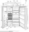
FIG. 1 provides a perspective view of a refrigerator appliance according to an example embodiment of the present subject matter.
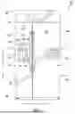
FIG. 2 provides a front view of the example refrigerator appliance of FIG. 1, with the doors of the fresh food chamber and freezer chamber shown in an open position.
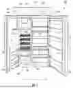
FIG. 3 provides a perspective view of a door assembly of the example refrigerator appliance of FIG. 1 according to an example embodiment of the present subject matter.
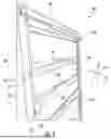
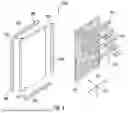
FIG. 4 provides an exploded view of the example door assembly of FIG. 3 according to an example embodiment of the present subject matter.
Repeat use of reference characters in the present specification and drawings is intended to represent the same or analogous features or elements of the present invention.
DETAILED DESCRIPTION OF THE INVENTION
Reference now will be made in detail to embodiments of the invention, one or more examples of which are illustrated in the drawings. Each example is provided by way of explanation of the invention, not limitation of the invention. In fact, it will be apparent to those skilled in the art that various modifications and variations can be made in the present invention without departing from the scope or spirit of the invention. For instance, features illustrated or described as part of one embodiment can be used with another embodiment to yield a still further embodiment. Thus, it is intended that the present invention covers such modifications and variations as come within the scope of the appended claims and their equivalents.
As used herein, the terms “first,” “second,” and “third” may be used interchangeably to distinguish one component from another and are not intended to signify location or importance of the individual components. The terms “includes” and “including” are intended to be inclusive in a manner similar to the term “comprising.” Similarly, the term “or” is generally intended to be inclusive (i.e., “A or B” is intended to mean “A or B or both”). The term “at least one of” in the context of, e.g., “at least one of A, B, and C” refers to only A, only B, only C, or any combination of A, B, and C. In addition, here and throughout the specification and claims, range limitations may be combined and/or interchanged. Such ranges are identified and include all the sub-ranges contained therein unless context or language indicates otherwise. For example, all ranges disclosed herein are inclusive of the endpoints, and the endpoints are independently combinable with each other. The singular forms “a,” “an,” and “the” include plural references unless the context clearly dictates otherwise.
Approximating language, as used herein throughout the specification and claims, may be applied to modify any quantitative representation that could permissibly vary without resulting in a change in the basic function to which it is related. Accordingly, a value modified by a term or terms, such as “generally,” “about,” “approximately,” and “substantially,” are not to be limited to the precise value specified. In at least some instances, the approximating language may correspond to the precision of an instrument for measuring the value, or the precision of the methods or machines for constructing or manufacturing the components and/or systems. For example, the approximating language may refer to being within a 10 percent margin, i.e., including values within ten percent greater or less than the stated value. In this regard, for example, when used in the context of an angle or direction, such terms include within ten degrees greater or less than the stated angle or direction, e.g., “generally vertical” includes forming an angle of up to ten degrees in any direction, e.g., clockwise or counterclockwise, with the vertical direction V.
The word “exemplary” is used herein to mean “serving as an example, instance, or illustration.” In addition, references to “an embodiment” or “one embodiment” does not necessarily refer to the same embodiment, although it may. Any implementation described herein as “exemplary” or “an embodiment” is not necessarily to be construed as preferred or advantageous over other implementations. Moreover, each example is provided by way of explanation of the invention, not limitation of the invention. In fact, it will be apparent to those skilled in the art that various modifications and variations can be made in the present invention without departing from the scope of the invention. For instance, features illustrated or described as part of one embodiment can be used with another embodiment to yield a still further embodiment. Thus, it is intended that the present invention covers such modifications and variations as come within the scope of the appended claims and their equivalents.
As explained herein, aspects of the present subject matter are generally directed to a refrigerator door that incorporates a magnetic paint applied to the inner surface of the door panel structure, where the magnets are placed on reinforcement brackets on the inside of the door or another sturdy structure of the door. The magnets on the brackets or other structures attract the inside surface of the door with magnetic paint, thereby enhancing the sturdiness of the door and eliminating potential canning effect when pressure is applied to the outside of the door. Having the inside of the surface of the door coated with magnetic paint allows the flexibility in design options for how magnets will connect to the reinforcement brackets or other structure on the door. Additionally, if the magnetic paint has a strong enough magnetic pull, the front of the refrigerator door becomes magnetic, enabling users to put magnets even if the door panel is made of wood or some other non-magnetic material.
FIG. 1 provides a perspective view of a refrigerator appliance 100 according to an exemplary embodiment of the present subject matter. Refrigerator appliance 100 includes a cabinet or housing 102 that extends between a top 104 and a bottom 106 along a vertical direction V, between a first side 108 and a second side 110 along a lateral direction L, and between a front side 112 and a rear side (not shown) along a transverse direction T. Each of the vertical direction V, lateral direction L, and transverse direction T are mutually perpendicular to one another.
Housing 102 defines chilled chambers for receipt of food items for storage. In particular, housing 102 defines fresh food chamber 122 positioned at or adjacent second side 110 of housing 102 and a freezer chamber 124 arranged at or adjacent first side 108 of housing 102. As such, refrigerator appliance 100 is generally referred to as a side-by-side refrigerator. It is recognized, however, that the benefits of the present disclosure apply to other types and styles of refrigerator appliances such as, e.g., a top mount refrigerator appliance, a bottom mount refrigerator appliance, or a single door refrigerator appliance. Consequently, the description set forth herein is for illustrative purposes only and is not intended to be limiting in any aspect to any particular refrigerator chamber configuration.
A refrigerator door 128 is rotatably hinged to an edge of housing 102 for selectively accessing fresh food chamber 122. In addition, a freezer door 130 is rotatably hinged to an edge of housing 102 for selectively accessing freezer chamber 124. Refrigerator door 128 and freezer door 130 are shown in the closed configuration in FIG. 1. One skilled in the art will appreciate that other chamber and door configurations are possible and within the scope of the present invention.
FIG. 2 provides a front view of refrigerator appliance 100 shown with refrigerator door 128 and freezer door 130 in the open position. As shown in FIG. 2, various storage components are mounted within fresh food chamber 122 to facilitate storage of food items therein as will be understood by those skilled in the art. In particular, the storage components may include bins 134 and shelves 136. Each of these storage components are configured for receipt of food items (e.g., beverages and/or solid food items) and may assist with organizing such food items. As illustrated, bins 134 may be mounted on refrigerator door 128 and freezer door 130 or may slide into a receiving space in fresh food chamber 122 or freezer chamber 124. It should be appreciated that the illustrated storage components are used only for the purpose of explanation and that other storage components may be used and may have different sizes, shapes, and configurations.
Referring now generally to FIG. 1, a dispensing assembly 140 will be described according to exemplary embodiments of the present subject matter. Dispensing assembly 140 is generally configured for dispensing liquid water and/or ice. Although an exemplary dispensing assembly 140 is illustrated and described herein, it should be appreciated that variations and modifications may be made to dispensing assembly 140 while remaining within the present subject matter.
Dispensing assembly 140 and its various components may be positioned at least in part within a dispenser recess 142 defined on freezer door 130. In this regard, dispenser recess 142 is defined on a front side 112 of refrigerator appliance 100 such that a user may operate dispensing assembly 140 without opening freezer door 130. In addition, dispenser recess 142 is positioned at a predetermined elevation convenient for a user to access ice and enabling the user to access ice without the need to bend-over. In the exemplary embodiment, dispenser recess 142 is positioned at a level that approximates the chest level of a user.
Dispensing assembly 140 includes an ice dispenser 144 including a discharging outlet 146 for discharging ice from dispensing assembly 140. An actuating mechanism 148, shown as a paddle, is mounted below discharging outlet 146 for operating ice or water dispenser 144. In alternative exemplary embodiments, any suitable actuating mechanism may be used to operate ice dispenser 144. For example, ice dispenser 144 can include a sensor (such as an ultrasonic sensor) or a button rather than the paddle. Discharging outlet 146 and actuating mechanism 148 are an external part of ice dispenser 144 and are mounted in dispenser recess 142.
Referring again to FIG. 2, inside refrigerator appliance 100, freezer door 130 may include an ice dispensing system 150 that generally includes one or more icemakers and ice storage bins 152 that are configured to form ice. In this regard, for example, ice dispensing system 150 may define an ice making chamber 154 for housing ice making assemblies, storage mechanisms, and dispensing mechanisms. According to the illustrated embodiment, ice dispensing system 150 may include dispensing assembly 140 and may have a main icemaker 156. In addition, ice dispensing system 150 may include an icemaker for forming “craft ice” that is commonly large, clear cubes or spheres of ice for alcoholic or non-alcoholic drinks. For example, a user may access this craft ice by opening freezer door 130 and accessing storage bin 152 directly.
A control panel 160 is provided for controlling the mode of operation. For example, control panel 160 includes one or more selector inputs 162, such as knobs, buttons, touchscreen interfaces, etc., such as a water dispensing button and an ice-dispensing button, for selecting a desired mode of operation such as crushed or non-crushed ice. In addition, inputs 162 may be used to specify a fill volume or method of operating dispensing assembly 140. In this regard, inputs 162 may be in communication with a processing device or controller 164. Signals generated in controller 164 operate refrigerator appliance 100 and dispensing assembly 140 in response to selector inputs 162. Additionally, a display 166, such as an indicator light or a screen, may be provided on control panel 160. Display 166 may be in communication with controller 164 and may display information in response to signals from controller 164.
As used herein, “processing device” or “controller” may refer to one or more microprocessors or semiconductor devices and is not restricted necessarily to a single element. The processing device can be programmed to operate refrigerator appliance 100 and dispensing assembly 140. The processing device may include, or be associated with, one or more memory elements (e.g., non-transitory storage media). In some such embodiments, the memory elements include electrically erasable, programmable read only memory (EEPROM). Generally, the memory elements can store information accessible processing device, including instructions that can be executed by processing device. Optionally, the instructions can be software or any set of instructions and/or data that when executed by the processing device, cause the processing device to perform operations.
Referring again briefly to FIG. 1, according to an exemplary embodiment, cabinet 102 also defines a mechanical compartment 170 at or near the bottom 106 of the cabinet 102 for receipt of a hermetically sealed cooling system 172. In general, sealed cooling system 172 is configured for transporting heat from the inside of refrigerator appliance 100 to the outside (e.g., by executing a vapor-compression cycle or another suitable refrigeration cycle). As is generally understood by those of skill in the art, the hermetically sealed system 172 contains a working fluid, e.g., refrigerant, which flows between various heat exchangers of the sealed system 172 where the working fluid changes phases while transferring thermal energy.
In this regard, as understood by one having ordinary skill in the art, sealed system 172 may include a compressor, a condenser, an expansion device, and one or more evaporators connected in series by a fluid conduit that is charged with a refrigerant. Within sealed system 172, refrigerant flows into the compressor, which operates to increase the pressure of the refrigerant. This compression of the refrigerant raises its temperature, which is lowered by passing the refrigerant through the condenser. Within the condenser, heat exchange with ambient air takes place so as to cool the refrigerant. A condenser fan may be used to pull air across the condenser, so as to provide forced convection for a more rapid and efficient heat exchange between the refrigerant within the condenser and the ambient air. Thus, as will be understood by those skilled in the art, increasing air flow across the condenser can, e.g., increase the efficiency of the condenser by improving cooling of the refrigerant contained therein.
An expansion device (e.g., an electronic expansion valve, capillary tube, or other restriction device) receives refrigerant from the condenser. From the expansion device, the refrigerant enters the evaporator. Upon exiting the expansion device and entering the evaporator, the refrigerant drops in pressure. Due to the pressure drop and/or phase change of the refrigerant, the evaporator is relatively cool. An evaporator fan is typically provided at each the evaporator, e.g., to force air across and around the at least one evaporator to transfer thermal energy from the air to the evaporator (and more particularly, to the working fluid or refrigerant therein).
In this manner, a flow of cooling air exits the evaporator and may be distributed to one or more of the chilled chambers 122 and/or 124. Specifically, one or more ducts may extend between the mechanical compartment 170 and the chilled chambers 122 and/or 124 to provide fluid communication therebetween, e.g., to provide the chilled air from the hermetically sealed cooling system 172, e.g., from an evaporator thereof, to one or more of the chilled chambers 122 and/or 124.
The sealed system 172 described herein is provided by way of example only. Thus, it is within the scope of the present subject matter for other configurations of the refrigeration system to be used as well. For example, according to alternative embodiments, sealed system 172 may include additional components, e.g., at least one additional evaporator, compressor, expansion device, and/or condenser. For example, refrigerator appliance 100 may have two or more split evaporators, e.g., one dedicated primarily to cooling fresh food chamber 122 and one dedicated primarily to cooling freezer chamber 124. In addition, alternative plumbing configurations, valves, and flow regulators may be used to route refrigerant throughout sealed system 172.
Referring now specifically to FIGS. 3 and 4, a door assembly 200 that may be used with refrigerator appliance 100 will be described according to an example embodiment of the present subject matter. In this regard, door assembly 200 may be utilized as refrigerator door 128, freezer door 130, or any other door of refrigerator appliance 100. Moreover, it should be appreciated that aspects of the present subject matter are equally applicable to any other suitable appliance. For example, the door constructions described herein may be used for dishwashers, oven appliances, microwaves, or any other suitable appliance.
As shown, door assembly 200 generally includes a door frame 202 that defines a perimeter of door assembly 200 and provides a primary structural support of door assembly 200. As illustrated, door frame 202 generally includes a plurality of frame members that are interconnected (e.g., using mechanical fasteners, welding, or any other suitable attachment method) to form a door structure. Specifically, door frame 202 includes a top frame member 204, a bottom frame member 206, and two side frame members 208. According to the illustrated embodiment, these frame members 204-208 are joined to form a substantially rectangular door perimeter.
In addition, door frame 202 may include one or more reinforcement brackets 210 that extend across the center of the door frame 202 for improving the rigidity and structural integrity of door frame 202. For example, according to the illustrated embodiment, reinforcement brackets 210 of door frame 202 extend along the lateral direction L between side frame members 208 and are spaced apart along the vertical direction V. As illustrated, reinforcement brackets 210 may be secured using one or more mechanical fasteners 212, though it should be appreciated that other attachment methods are possible and within the scope of the present subject matter. Although only horizontal reinforcement brackets 210 are illustrated, it should be appreciated that vertical reinforcement brackets or any other suitable reinforcing structure may be used while remaining within the scope of the present subject matter.
Door assembly 200 may further include an outer door panel 220 that is mounted to door frame 202. Specifically, outer door panel 220 may define and outer surface 222 (e.g., the appearance face of refrigerator appliance 100) and an inner surface 224 (e.g., which is connected to door frame 202 and defines an inner door plenum). According to the illustrated embodiment, outer door panel 220 may be formed from sheet metal, e.g., such as stainless steel or any other suitable rigid material. According to still other embodiments, outer door panel 220 may be formed from wood, plastic, or any other suitable material.
Notably, as explained briefly above, outer door panel 220 may be attached to door frame 202 in a manner that prevents flexing, deformation, buckling, canning, or relative motion between outer door panel and door frame 202, e.g., particularly when a user or an object presses against the door assembly 200. This deformation or movement may result in user perception of a low-quality door, increased noise, and general user dissatisfaction. Accordingly, aspects of the present subject matter are generally directed to features for improving the rigidity, noise reduction, and quality of door assembly 200.
For example, as best illustrated in FIGS. 3 and 4, door assembly 200 may include a magnetic material 230 that is applied to at least a portion of outer door panel 220. More specifically, magnetic material 230 may be applied to inner surface 224 of outer door panel 220. According to an example embodiment, magnetic material 230 may be magnetic paint, a magnetic adhesive pad, or permanent magnets that are securely attached to outer door panel 220. In general, magnetic material 230 is intended to facilitate magnetic attraction between outer door panel 220 and door frame 202, as described in more detail below. In addition, by magnetizing outer door panel 220, magnets may be attracted to outer surface 222 of outer door panel 220, e.g., to facilitate attachment of cabinet fronts or other components.
According to an example embodiment, door assembly 200 may further include one or more magnets 240 mounted to door frame 202. According to an example embodiment, magnets 240 are positioned to ensure firm contact and structural rigidity between door frame 202 and outer door panel 220, e.g., via magnetic attraction with magnetic material 230. For example, magnets 240 may be mounted to reinforcement brackets 210 to engage outer door panel 220 and prevent any undesirable deformation of outer door panel 220. According to the illustrated embodiment, magnets 240 are positioned proximate a center of door frame 202 along the lateral direction L, though other suitable positioning is possible and within the scope of the present subject matter.
It should be appreciated that magnetic material 230 may be localized, e.g., proximate reinforcement brackets 210, proximate magnets 240, etc. According to alternative embodiments, magnetic material 230 may cover an entirety of inner surface 224 of outer door panel 220. Other configurations or magnetic material 230 and magnets 240 are possible and within the scope of the present subject matter. For example, the type, size, positioning, and configuration of these components may vary while remaining within the scope of the present subject matter.
This written description uses examples to disclose the invention, including the best mode, and also to enable any person skilled in the art to practice the invention, including making and using any devices or systems and performing any incorporated methods. The patentable scope of the invention is defined by the claims, and may include other examples that occur to those skilled in the art. Such other examples are intended to be within the scope of the claims if they include structural elements that do not differ from the literal language of the claims, or if they include equivalent structural elements with insubstantial differences from the literal language of the claims.
Claims
What is claimed is:1. A refrigerator appliance defining a vertical direction, a lateral direction, and a transverse direction, the refrigerator appliance comprising:
a cabinet defining a chilled chamber; and
a door assembly rotatably mounted to the cabinet to provide selective access to the chilled chamber, the door assembly comprising:
a door frame defining a perimeter of the door assembly;
an outer door panel mounted to the door frame, wherein a magnetic material is applied to at least a portion of the outer door panel; and
one or more magnets mounted to the door frame, the one or more magnets being mechanically coupled to the magnetic material to attach the outer door panel to the door frame.
2. The refrigerator appliance of claim 1, wherein the magnetic material is applied to an inner surface of the outer door panel.
3. The refrigerator appliance of claim 2, wherein the magnetic material is localized around the one or more magnets on the door frame.
4. The refrigerator appliance of claim 2, wherein the magnetic material covers an entirety of the inner surface of the outer door panel.
5. The refrigerator appliance of claim 1, wherein the magnetic material is magnetic paint.
6. The refrigerator appliance of claim 1, wherein the magnetic material is a magnetic adhesive pad.
7. The refrigerator appliance of claim 1, wherein the one or more magnets are positioned proximate a center of the door frame along the lateral direction.
8. The refrigerator appliance of claim 1, wherein the door frame comprises a plurality of reinforcement brackets extending across a center of the door frame, wherein the one or more magnets are mounted to the plurality of reinforcement brackets.
9. The refrigerator appliance of claim 8, wherein the plurality of reinforcement brackets extend along the lateral direction and are spaced apart along the vertical direction.
10. The refrigerator appliance of claim 8, wherein the plurality of reinforcement brackets are attached to side brackets of the door frame using one or more mechanical fasteners.
11. The refrigerator appliance of claim 1, wherein the outer door panel is formed from stainless steel.
12. A door assembly for an appliance, the appliance comprising a cabinet defining an internal chamber, the door assembly comprising:
a door frame defining a perimeter of the door assembly;
an outer door panel mounted to the door frame, wherein a magnetic material is applied to at least a portion of the outer door panel; and
one or more magnets mounted to the door frame, the one or more magnets being mechanically coupled to the magnetic material to attach the outer door panel to the door frame.
13. The door assembly of claim 12, wherein the magnetic material is applied to an inner surface of the outer door panel.
14. The door assembly of claim 13, wherein the magnetic material is localized around the one or more magnets on the door frame.
15. The door assembly of claim 13, wherein the magnetic material covers an entirety of the inner surface of the outer door panel.
16. The door assembly of claim 12, wherein the magnetic material is magnetic paint.
17. The door assembly of claim 12, wherein the magnetic material is a magnetic adhesive pad.
18. The door assembly of claim 12, wherein the one or more magnets are positioned proximate a center of the door frame along the lateral direction.
19. The door assembly of claim 12, wherein the door frame comprises a plurality of reinforcement brackets extending across a center of the door frame, wherein the one or more magnets are mounted to the plurality of reinforcement brackets.
20. The door assembly of claim 19, wherein the plurality of reinforcement brackets extend along the lateral direction and are spaced apart along a vertical direction.
Images & Drawings included:
Sources:
- United States Patent and Trademark Office - verify current appl. status at the USPTO↗
Similar patent applications:
- » 20240418433
DOOR ASSEMBLY FOR REFRIGERATION APPLIANCE AND REFRIGERATION APPLIANCE - » 15961967
Refrigerator appliance and door assembly having an interior panel - » 20250116452
DRAWER IN DOOR ASSEMBLY FOR A REFRIGERATOR APPLIANCE - » 20100218526
Door assembly for a refrigeration appliance - » 20200284500
Door gasket assembly for a refrigerated appliance - » 20210148626
Latching assemblies for door-in-door refrigerator appliances - » 20220042737
Door gasket assembly for a refrigerated appliance - » 20230035409
DOOR ASSEMBLY, AND REFRIGERATOR AND HOME APPLIANCE INCLUDING SAME - » 20260023207
DOOR ASSEMBLY, AND REFRIGERATOR AND HOME APPLIANCE INCLUDING SAME - » 20150198365
Door module assembly for a refrigerator appliance
Recent applications in this class:
- » 20260063354 2026-03-05
REFRIGERATOR AND METHOD FOR MANUFACTURING REFRIGERATOR DOOR - » 20260049755 2026-02-19
REFRIGERATOR APPLIANCE WITH ADJUSTABLE SCREEN - » 20260043601 2026-02-12
REFRIGERATION APPLIANCE - » 20260043600 2026-02-12
REFRIGERATOR - » 20260029188 2026-01-29
REFRIGERATOR APPLIANCE - » 20260029187 2026-01-29
PCM STEEL SHEET FOR HOME APPLIANCES AND REFRIGERATOR INCLUDING THE SAME - » 20260029186 2026-01-29
LOCATOR RAIL FOR APPLIANCE DOOR HINGE - » 20260022884 2026-01-22
REFRIGERATOR - » 20260016221 2026-01-15
REFRIGERATOR - » 20260016220 2026-01-15
REFRIGERATOR