Multi-Mode Adiabatic Cooling System with Deluge Feature
US20260063380A1
2026-03-05
19/081,835
2025-03-17
Smart Summary: A cooling system uses air to lower the temperature of fluids. It can work in three or four different ways. In dry mode, it cools by using dry air blown through tubes. In adiabatic mode, air is cooled by wet pads before it enters the tubes. The system can also use evaporative cooling by wetting the tubes, and in the fourth mode, both the pads and tubes can be wet for maximum cooling. 🚀 TL;DR
Abstract:
An air-cooled adiabatic heat exchanger for cooling fluids having tube bundles for receiving hot process and rendering cooled fluid, operating in three or four modes. In a dry mode, heat is exchanged with dry air drawn through the tube bundles by fans. In an adiabatic mode, air entering the heat exchanger is adiabatically pre-cooled by water-saturated adiabatic pads, while the tube bundles remain dry. In an evaporative mode, the adiabatic pads remain dry, and the tubes are wetted with evaporative cooling water. In an optional fourth mode, both the adiabatic pads and the tubes are wetted.
Inventors:
- Natasha Rinehart 2 🇺🇸 Taneytown, MD, United States
- Rob Vandenboer 2 🇺🇸 Taneytown, MD, United States
- Mathew Rutherford 1 🇺🇸 Taneytown, MD, United States
- Sean Wilson 1 🇺🇸 Taneytown, MD, United States
- Graham Nettleton 1 🇺🇸 Taneytown, MD, United States
Applicant:
Interested in similar patents?
Get notified when new applications in this technology area are published.
Classification:
F28F27/003 » CPC main
Control arrangements or safety devices specially adapted for heat-exchange or heat-transfer apparatus specially adapted for cooling towers
F28D5/02 » CPC further
Heat-exchange apparatus having stationary conduit assemblies for one heat-exchange medium only, the media being in contact with different sides of the conduit wall, using the cooling effect of natural or forced evaporation in which the evaporating medium flows in a continuous film or trickles freely over the conduits
F28F25/04 » CPC further
Component parts of trickle coolers for distributing, circulating, and accumulating liquid Distributing or accumulator troughs
F28F27/00 IPC
Control arrangements or safety devices specially adapted for heat-exchange or heat-transfer apparatus
Description
FIELD OF THE INVENTION
The invention relates to adiabatic coolers.
SUMMARY OF THE INVENTION
The present invention is directed to enhancing the performance of adiabatic cooling equipment using evaporative assistance/boosting. According to the invention, the number of chillers required for a specific capacity is reduced and the number of coolers required on a given project may therefore be reduced correspondingly.
Accordingly, there is provided according to the invention a fluid cooler comprising: a frame, one or more pairs of tube bundles arranged in the frame and flanking a plenum, each of the tube bundles having an inlet header and an outlet header, the inlet header configured and located to receive hot process fluid and to distribute it to a corresponding tube bundle and the outlet header configured and located to receive cooled process fluid from the tube bundle, the tube bundles each comprising a plurality of horizontally arranged finned tubes connected to adjacent tubes with tube bends, one or more fans supported in the frame above the tube bundles configured to draw air through the tube bundles and out through a top of the fan(s), one or more adiabatic pads mounted in the frame adjacent to air intake sides of the tube bundles, an adiabatic cooling water distribution system located above and configured to selectively deliver adiabatic cooling water to and saturate the adiabatic pads, an adiabatic cooling water collection tray located below the adiabatic pad(s) and connected to a drain or to an adiabatic water recirculation system, including a sump, a pump, and pipes connecting the sump and pump to the adiabatic cooling water distribution system, an evaporative cooling water distribution system located above the tube bundles and configured to selectively deliver evaporative cooling water to outside surfaces to the tube bundles, an evaporative cooling water collection tray located below the tube bundles and connected to a drain or to an evaporative cooling water recirculation system, and a plurality of valves located and configured to selectively permit delivery of water only to the adiabatic pads, delivery of water only to the tube bundles, delivery of water to both adiabatic pads and to the tube bundles simultaneously, or to prevent delivery of water to the adiabatic pads and to the tube bundles. A control system may be provided connected to the plurality of valves and configured to selectively open and close each of the plurality of valves to selectively operate the fluid cooler in a dry mode, in which no water is delivered to the adiabatic pads or to the tube bundles, in an adiabatic mode in which water is delivered only to the adiabatic pads, or in an evaporative mode, in which water is delivered only to the tube bundles. According to a further embodiment, a further combined mode may be provided in which water is delivered to the adiabatic pads and to the tube bundles simultaneously.
There is also provided according to the invention a method for operating a fluid cooler having tube bundles arranged in a frame and flanking a plenum, the tube bundles each having an inlet header and an outlet header, the inlet header configured and located to receive hot process fluid and to distribute it to a corresponding tube bundle and the outlet header configured and located to receive cooled process fluid from the tube bundle, the two tube bundles each comprising a plurality of horizontally arranged finned tubes connected to adjacent tubes with tube bends, one or more fans supported by the frame above the tube bundles configured to draw air through the tube bundles and out through a top of the fan, one or more adiabatic pads mounted in the frame adjacent to air intake sides of the tube bundles, a first water distribution system located and configured to selectively deliver adiabatic water to the adiabatic pads, and a second water distribution located and configured to selectively deliver evaporative cooling water to the tube bundles, the method comprising selectively operating the fluid cooler in any one of three modes, depending on environmental conditions: in a dry mode, in which no water is delivered to the adiabatic pads or to the tube bundles, in an adiabatic mode in which water is delivered only to the adiabatic pads, or in an evaporative mode, in which water is delivered only to the tube bundles. According to a further embodiment, a further combined mode may be provided in which water is delivered to the adiabatic pads and to the tube bundles simultaneously.
BRIEF DESCRIPTION OF DRAWINGS
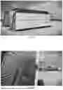
FIG. 1 shows a perspective view of two air cooled heat exchangers on which adiabatic pads have been mounted.
FIG. 2 shows a close-up, side cutaway view of one of the air cooled heat exchangers shown in FIG. 1.
FIG. 3 is a representation of the operation of the air cooled heat exchanger with adiabatic pre-cooling shown in FIGS. 1 and 2.
FIG. 4 is a schematic showing adiabatic and evaporative (deluge) operational modes according to an embodiment of the invention.
DETAILED DESCRIPTION OF THE INVENTION
An example of a cooler with adiabatic pre-cooling pads is shown in FIGS. 1 and 2. A frame encloses two tube bundles, each comprising a plurality of horizontally arranged finned tubes. While the tube bundles shown in FIGS. 1 and 2 are shown in a V-shaped configuration, they may be arranged vertically in a parallel arrangement, or in any other suitable arrangement depending on the size and space requirements of the system. At one end of each tube bundle, the tubes are connected at an inlet end to an inlet header and to an outlet header. At an opposite end of each bundle, each horizontal tube is connected to an adjacent horizontal tube via a return bend. A hot process fluid enters the inlet header via an inlet header connection and is then distributed to the tubes from the inlet header. Cooled fluid exits the tubes via an outlet header and returns to the process/system that headed the fluid. Adiabatic pads are mounted along and spanning both sides of the unit left-to-right and top-to-bottom. An adiabatic cooling water distribution system, comprising tubes and sprayers, nozzles and/or distribution plates or trays, is located above the tops of the pads. When activated, the adiabatic cooling water distribution system delivers sufficient water to the pads to keep them saturated. Water collection trays are provided at the bottom of each set of pads to collect water that is not evaporated at the pads. An adiabatic cooling water recirculation system including overflow sump or tank, pump and tubes, may be provided to save water that is collected in the adiabatic water collection trays and, when needed, circulate it back to the adiabatic cooling water distribution system. Alternatively, or in addition, water collected from the adiabatic pads may be sent to a drain. A fresh-water supply may be provided to add additional water to the system as required due to evaporation and other water loss. The frame supports a plurality of fans at the top of the cooler and draws ambient air into the unit through the pads, past the tubes and the fins and out the top of the unit.
The coolers of the invention additionally include an evaporative cooling water delivery system located above the tube bundles, away from the adiabatic pads. As with the adiabatic cooling water delivery system, the evaporative cooling water delivery system may comprise tubes and sprayers, nozzles and/or perforated trays. The evaporative cooling water delivery system is located and configured to deliver water, when needed, to the tubes and fins of the tube bundles. An evaporative water collection tray may be located beneath the tube bundles to collect evaporative cooling water that falls from the tube bundles. Evaporative water collected from the tube bundles may be sent to a drain, may be collected in a sump or tank (which may be the same as or different from the adiabatic cooling water sump or tank) for recirculation to the evaporative cooling water delivery system via pump and tubes.
The evaporative cooling water delivery and recirculation systems may be entirely separate from the adiabatic cooling water delivery and recirculation systems, or the two water delivery and recirculation systems may share significant portions with one-another.
Devices according to the invention are designed and configured to operate in three different modes: 1)Primary Cooling Mode—Dry Cooling, 2) Secondary Cooling Mode—Adiabatic Cooling, and 3) Tertiary Cooling Mode—Evaporative Cooling. Optionally, the devices may operate in a Quaternary Cooling Mode—Combined Adiabatic and Evaporative Cooling.
The main mode of an “Hybrid Dry Cooler” according to the invention is to cool a fluid by passing it through a dry fin tube heat exchanger which is cooled by a stream of dry air, without wetting. Hot process fluid, shown in red, enters the inlet header via the inlet header connection. From the inlet header, the hot process fluid travels transversely across the heat exchanger, generally parallel to the horizontal. Dry ambient air is drawn over the coil surface by the fans located at the top of the unit, without wetting the heat exchanger or cooling the ambient air stream. Heat from the process fluid dissipates through the tube surfaces and out to the fins (not shown) and is transferred to the air and discharged to the atmosphere. Cool process fluid, shown in blue, exits the unit through the outlet headers. The multi-mode cooler of the invention will prioritize the Primary Cooling (Dry) operation.
Secondary Cooling Mode—Adiabatic Cooling
In adiabatic mode, represented by the green and red lines in FIG. 4, the fin tube heat exchange surface still remains completely dry. No heat is transferred to the adiabatic cooling water via the heat exchange surface. The air is adiabatically cooled by saturating the adiabatic pads located in the incoming air stream. The dry bulb temperature of the incoming air is depressed to within a few degrees of the wet bulb temperature. This pre-cooled air is then drawn through the tube and fin surface, offering a substantial increase in heat rejection capability. Heat from the process fluid transfers to the air and discharged to the atmosphere. Cool process fluid, shown in blue, exits the unit through the outlet headers. In a recirculating water system, the water used to wet the adiabatic pads and which is not evaporated is collected at the bottom of the unit and recirculated to a water distribution system at the top of the pad. In a once-through water system, the water used to wet the adiabatic pads and which is not evaporated is collected and sent to a drain. The new air temperature is referred to as the depressed dry bulb. Approximately 80-90% saturation can be achieved. No sprays are used, and no aerosols are detectable at the air discharge. Hot process fluid, shown in red, enters the inlet header via the inlet header connection. From the inlet header, the hot process fluid travels transversely across the heat exchanger, generally parallel to the horizontal. Heat from the process fluid dissipates through the coil tubes surface and out to the fins (not shown). According to the present invention, however, all wetting water is completely drained once Dry Mode is re-activated. All drainage valves are fail-safe and gravity fed.
Tertiary Cooling Mode—Evaporative (Wet) Cooling
According to the additional evaporative mode, represented by the purple and blue lines in FIG. 4, wetting water is provided to a separate deluge wetting system which applies water directly onto the heat exchange surface, out of the air stream, preferably in an enclosed box or header, so that no aerosols are detectable at the air discharge. According to preferred embodiments, the evaporative water distribution system is located immediately and closely above top of the tube bundles, outside of the airflow generated by fans. Fan speed and water delivery are carefully monitored and adjusted to 1) maintain the falling water on the tubes, preventing water from falling vertically in the case of slanted tube bundles, and 2) have water evaporate from the tubes/fins or fall to the below/adjacent tubes/fins before the force of the air blows it into and up through the plenum. Operation in this mode is intended to be limited to less than a pre-determined number of hours or percent of the year. While the air stream continues to pass through the cellulose media/pads during this mode, no water is applied to the pads. All wetting water is completely drained once the primary “dry” mode (where no adiabatic water or evaporative water is distributed to the adiabatic pad(s) or tube bundles) is re-activated. All drainage valves are fail-safe and gravity fed.
According to various alternative embodiments of the invention, the devices of the invention may be implemented without water treatment systems or features, as the operation of the evaporative mode may be sufficiently limited, given the availability of the adiabatic mode, so that scaling of the tube bundles is significantly reduced or even eliminated.
Notwithstanding the specific embodiments, features, elements, combinations and sub-combinations disclosed herein, it is expressly considered and here disclosed that every single element, every single feature, and every combination and sub-combination thereof disclosed herein may be combined with every other element, feature, combination and sub-combination disclosed herein.
It will be appreciated by those skilled in the art that changes could be made to the embodiments described above without departing from the inventive concept thereof. It is understood, therefore, that this invention is not limited to the particular embodiments disclosed, but it is intended to cover modifications within the spirit and scope of the present invention as outlined in the present disclosure and defined according to the broadest reasonable reading of the claims that follow, read in light of the present specification.
Claims
1. A fluid cooler, comprising:
a frame,
one or more pairs of tube bundles arranged in said frame and flanking a plenum,
each of said tube bundles having an inlet header and an outlet header, said inlet header configured and located to receive hot process fluid and to distribute it to a corresponding tube bundle and said outlet header configured and located to receive cooled process fluid from said tube bundle,
each of said tube bundles comprising a plurality of horizontally arranged finned tubes connected to adjacent tubes with tube bends,
one or more fans above said tube bundles configured to draw air through said tube bundles and out through a top of said one or more fans,
one or more adiabatic pads mounted adjacent to air intake sides of said tube bundles,
an adiabatic cooling water distribution system located above said one or more adiabatic pads and configured to selectively deliver adiabatic cooling water to and saturate said one or more adiabatic pads,
an adiabatic cooling water collection tray located below said adiabatic pads and connected to a drain and/or to an adiabatic water recirculation system, including a sump, a pump, and pipes connecting said sump and pump to said adiabatic cooling water distribution system,
an evaporative cooling water distribution system located above said tube bundles and configured to selectively deliver evaporative cooling water to outside surfaces to said tube bundles,
an evaporative cooling water collection tray located below said tube bundles and connected to a drain and/or to an evaporative cooling water recirculation system in turn connected to said evaporative cooling water distribution system,
a plurality of valves located and configured to selectively permit delivery of water only to said adiabatic pads, delivery of water only to said tube bundles, or to prevent delivery of water to said adiabatic pads and to said tube bundles,
a control system connected to said plurality of valves and configured to selectively open and close each of said plurality of valves to selectively operate said fluid cooler in a dry mode, in which no water is delivered to said adiabatic pads or to said tube bundles, in an adiabatic mode in which water is delivered only to said adiabatic pads, or in an evaporative mode, in which water is delivered only to said tube bundles.
2. The fluid cooler of claim 1, wherein said control system is further configured to open and close each of said plurality of valves to selectively operate in a combined adiabatic and evaporative mode in which water is delivered both to said adiabatic pads and to said tube bundles.
3. The fluid cooler of claim 1, wherein said evaporative cooling water recirculation system and said adiabatic cooling water re circulation system are integrated with one-another.
4. A method for operating a fluid cooler having tube bundles arranged in a frame and flanking a plenum, said tube bundles each having an inlet header and an outlet header, said inlet header configured and located to receive hot process fluid and to distribute it to a corresponding tube bundle and said outlet header configured and located to receive cooled process fluid from said tube bundle, said two tube bundles each comprising a plurality of horizontally arranged finned tubes connected to adjacent tubes with tube bends, one or more fans above said tube bundles configured to draw air through said tube bundles and out through a top of said one or more fans, one or more adiabatic pads mounted adjacent to air intake sides of said tube bundles, a first water distribution system located and configured to selectively deliver adiabatic water to said one or more adiabatic pads, and a second water distribution located and configured to selectively deliver evaporative cooling water to said tube bundles,
said method comprising selectively operating said fluid cooler in any one of a plurality of modes, depending on environmental conditions, including: in a dry mode, in which no water is delivered to said one or more adiabatic pads or to said tube bundles, in an adiabatic mode in which water is delivered only to said one or more adiabatic pads, or in an evaporative mode, in which water is delivered only to said tube bundles.
5. The method of claim 4, further comprising selectively operating said fluid cooler in a combined adiabatic and evaporative mode in which water is delivered both to said one or more adiabatic pads and said tube bundles.
6. The method of claim 4, wherein said evaporative cooling water recirculation system and said adiabatic cooling water re circulation system are integrated with one-another.
Images & Drawings included:


Sources:
- United States Patent and Trademark Office - verify current appl. status at the USPTO↗
Recent applications in this class:
- » 20250314438 2025-10-09
INTEGRATED FAN DRIVE SYSTEM FOR COOLING TOWER - » 20250216163 2025-07-03
INTEGRATED FAN DRIVE SYSTEM FOR COOLING TOWER - » 20250075991 2025-03-06
FAN BRAKE CONTROL SYSTEM - » 20240384952 2024-11-21
COOLING TOWER AND METHOD FOR MONITORING AND CONTROLLING A COOLING TOWER - » 20240337454 2024-10-10
DIRECT-DRIVE SYSTEM FOR COOLING SYSTEM FANS, EXHAUST BLOWERS AND PUMPS - » 20230221085 2023-07-13
Operation control system and method for a chiller cooling tower - » 20230194196 2023-06-22
Pulsing adiabatic gas cooler - » 20230105109 2023-04-06
COOLING TOWER CONTROL METHOD AND SYSTEM - » 20230018836 2023-01-19
Fan brake control system - » 20220390194 2022-12-08
Direct-drive system for cooling system fans, exhaust blowers and pumps