AEROSOL GENERATING DEVICE AND AEROSOL GENERATING SYSTEM
US20260068942A1
2026-03-12
19/392,458
2025-11-18
Smart Summary: An aerosol generating device uses a special setup to create aerosol. It has two parts called conductors that work together to form a space where heating happens. This space heats up a material that turns into aerosol. Microwaves are sent into this space to help produce the aerosol. The device is designed to efficiently generate aerosol for various uses. 🚀 TL;DR
Abstract:
An aerosol generating device includes a conductor assembly and a microwave assembly. The conductor assembly includes a first conductor and a second conductor that jointly form a resonant cavity. The resonant cavity includes at least a heating region, and the heating region is configured to heat an aerosol generating article. The microwave assembly is configured to feed a microwave into the resonant cavity to generate an aerosol.
Inventors:
- Bin Chen 58 🇨🇳 Shenzhen, China
- Jun You 9 🇨🇳 Shenzhen, China
- Hongming ZHOU 55 🇨🇳 Shenzhen, China
- Rihong LI 25 🇨🇳 Shenzhen, China
- Hongyi LIU 1 🇨🇳 Shenzhen, China
Assignee:
- Verdewell International Holdings Limited 1 Grand Cayman, Cayman Islands
Applicant:
Interested in similar patents?
Get notified when new applications in this technology area are published.
Classification:
A24F40/46 » CPC main
Electrically operated smoking devices; Component parts thereof; Manufacture thereof; Maintenance or testing thereof; Charging means specially adapted therefor; Constructional details, e.g. connection of cartridges and battery parts Shape or structure of electric heating means
A24F40/48 » CPC further
Electrically operated smoking devices; Component parts thereof; Manufacture thereof; Maintenance or testing thereof; Charging means specially adapted therefor; Constructional details, e.g. connection of cartridges and battery parts Fluid transfer means, e.g. pumps
Description
CROSS-REFERENCE TO RELATED APPLICATIONS
This application is a continuation application of International application No. PCT/CN2024/088077, filed on Apr. 16, 2024, which claims the priority to and benefit of Chinese Patent Application No. 202310565460.8 filed on May 18, 2023. The entire disclosure of the prior applications are hereby incorporated by reference.
TECHNICAL FIELD
This application relates to the field of vaporization technologies, including to an aerosol generating device and an aerosol generating system.
BACKGROUND
Currently, an aerosol generating device is widely popular on the market, and a heating manner of the aerosol generating device is continuously improved. A microwave heating technology gradually becomes mainstream. However, in the related technology, an inner conductor and an outer conductor in a microwave resonant cavity are not easily disassembled. A vaporized aerosol condenses on the inner conductor or an inner surface of the outer conductor, which causes dirt to be formed over a long time, affecting inhalation taste, and even endangering human health.
SUMMARY
The aerosol generating device of the aspects of this disclosure includes a conductor assembly and a microwave assembly. The conductor assembly includes a first conductor and a second conductor, the first conductor and the second conductor are detachably combined and jointly form a resonant cavity, the resonant cavity includes at least a heating region, and the heating region is used to heat an aerosol generating article. The microwave assembly is configured to feed a microwave into the resonant cavity, for the aerosol generating article to generate an aerosol.
In some aspects, the first conductor includes a first end and a second end that are opposite to each other, the first conductor is provided with an accommodating cavity, the first end is provided with an opening communicating with the accommodating cavity and the outside, the second conductor includes a first end and a second end that are opposite to each other, the first end of the second conductor is detachably mounted at the opening, the second end of the second conductor extends into the accommodating cavity and is spaced apart from the second end of the first conductor, and the heating region is formed at the spacing.
In some aspects, the first conductor and the second conductor are coaxially arranged, to form the coaxial resonant cavity.
In some aspects, the second conductor includes a cover body and an inner conductor. The cover body is configured to connect to the opening, where the cover body includes a first side and a second side that face away from each other, the second side of the cover body is closer to the accommodating cavity than the first side of the cover body, the cover body is provided with a first through hole and a second through hole that run through the first side of the cover body and the second side of the cover body, and the second through hole is spaced apart from the first through hole. The inner conductor is arranged on the second side of the cover body and at least partially extends into the accommodating cavity, the inner conductor includes a first end and a second end that are opposite to each other, the first end of the inner conductor is closer to the cover body than the second end of the inner conductor, the inner conductor is provided with a channel that run through the first end and the second end of the inner conductor, and the channel is in communication with the first through hole.
In some aspects, a run-through via is provided on a peripheral wall of the inner conductor, and the via is in communication with the channel.
In some aspects, the second conductor further includes a suction nozzle. The suction nozzle is arranged on the first side of the cover body, the suction nozzle is provided with an inhalation hole running through two opposite ends of the suction nozzle, the inhalation hole is in communication with the first through hole, and the inhalation hole, the first through hole, and the channel jointly form a first airway passage. The second through hole forms a second airway passage communicating with the accommodating cavity and external air.
In some aspects, the second conductor further includes a suction nozzle. The suction nozzle is arranged on the first side of the cover body, an air inlet hole is provided on a side wall of the suction nozzle, the air inlet hole is in communication with the first through hole to form a first airway passage, the suction nozzle is further provided with an inhalation hole and a converging hole that are connected to each other, the inhalation hole runs through one end of the suction nozzle away from the cover body, two opposite ends of the converging hole are respectively in communication with the inhalation hole and the second through hole, the inhalation hole is in communication with the second through hole to form a second airway passage, a blocking portion is arranged between the inhalation hole and the first through hole, and the converging hole surrounds the blocking portion.
In some aspects, the microwave assembly includes a microwave feed member, a microwave transmitting source, and a microwave transmission member. The first conductor is provided with a feed hole, the feed hole is in communication with the resonant cavity and is configured to allow the microwave feed member to pass through the resonant cavity, and the microwave feed member is configured to feed a microwave into the resonant cavity. The microwave transmitting source is configured to transmit a microwave. Two opposite ends of the microwave transmission member are respectively connected to the microwave transmitting source and the microwave feed member, and the microwave transmission member is configured to transmit the microwave transmitted by the microwave transmitting source to the microwave feed member.
In some aspects, the aerosol generating device further includes a housing, a control assembly, and a power supply unit. The conductor assembly, the microwave assembly, the control assembly, and the power supply unit are all arranged in the housing. The control assembly includes a circuit board and a controller arranged on the circuit board, and the controller is configured to control an operating status of the microwave transmitting source. The power supply unit is configured to supply power to the microwave assembly and the control assembly.
In some aspects, the microwave transmitting source is a solid-state microwave source.
In some aspects, the accommodating cavity is in a stepped shape and includes a plurality of sub-cavities, opening sizes of cross sections of at least two sub-cavities are different, and a side wall of at least one sub-cavity is in contact with a side wall of the aerosol generating article, to limit a position of the aerosol generating article in the accommodating cavity.
In some aspects, a limiting member is arranged in the accommodating cavity, the limiting member is connected to the first conductor, and the limiting member is configured to limit a position of the aerosol generating article in the accommodating cavity, for a side wall of the accommodating cavity and the aerosol generating article to be spaced apart from each other.
In some aspects, the limiting member is made of a microwave low-loss medium material, and the limiting member is filled in at least a part of a spacing between the first conductor and the aerosol generating article.
In some aspects, a blocking member is arranged in the accommodating cavity, the blocking member is made of a microwave low-loss medium material, the blocking member is arranged on the first end of the first conductor, the blocking member is provided with a through hole, and the through hole surrounds the aerosol generating article.
An aerosol generating system of this disclosure includes the aerosol generating device according to any one of the foregoing aspects and an aerosol generating article. The aerosol generating article is loaded in the resonant cavity, and the second conductor at least partially extends into the aerosol generating article.
In some aspects, the aerosol generating article includes a loading member and an aerosol generating substance. The loading member is detachably loaded in the resonant cavity, and one end of the second conductor extends into the loading member. The aerosol generating substance is loaded in the loading member, and the aerosol generating substance is located in the heating region.
In some aspects, the loading member is made of a microwave low-loss material.
In some aspects, a microwave high-loss material is arranged in the aerosol generating substance.
In some aspects, a porous ceramic material is arranged in the aerosol generating substance.
In the aerosol generating device and the aerosol generating system of this disclosure, the microwave assembly feeds a microwave into the resonant cavity jointly formed by the first conductor and the second conductor, for the aerosol generating article to generate an aerosol. The first conductor and the second conductor are easily disassembled and separated, to facilitate cleaning of the resonant cavity, and greatly reduce or even avoid dirt remaining in the resonant cavity, thereby ensuring good inhalation taste and maintaining health and safety of a human body.
Additional aspects and advantages of the aspects of this disclosure will be given in the following descriptions, some of which will become apparent from the following descriptions or may be learned through practices of the aspects of this disclosure.
BRIEF DESCRIPTION OF THE DRAWINGS
The foregoing and/or additional aspects and advantages of this disclosure will become apparent and comprehensible from the descriptions of the aspects below with reference to the accompanying drawings.
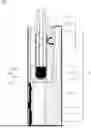
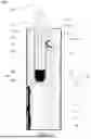
FIG. 1 is a schematic structural diagram of an aerosol generating system according to some aspects of this disclosure.
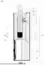
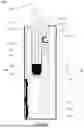
FIG. 2 is a schematic exploded view of an aerosol generating system shown in FIG. 1.
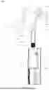
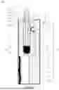
FIG. 3 is a schematic circulation diagram of an aerosol generating system shown in FIG. 1.
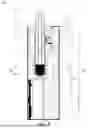
FIG. 4 is a schematic structural diagram of an aerosol generating system according to some other aspects of this disclosure.
FIG. 5 is a schematic structural diagram of an aerosol generating system according to some still other aspects of this disclosure.
FIG. 6 is a schematic structural diagram of an aerosol generating system according to some yet other aspects of this disclosure.
FIG. 7 is a schematic structural diagram of an aerosol generating system according to some still yet other aspects of this disclosure.
FIG. 8 is a schematic structural diagram of an aerosol generating system according to some other aspects of this disclosure.
FIG. 9 is a schematic structural diagram of an aerosol generating system according to some still other aspects of this disclosure.
FIG. 10 is a schematic structural diagram of an aerosol generating system according to some yet other aspects of this disclosure.
DETAILED DESCRIPTION
The following describes aspects of this disclosure in detail. Examples of the aspects are shown in the accompanying drawings, and same or similar reference signs in all the accompanying drawings indicate same or similar components or components having same or similar functions. The aspects that are described with reference to the accompany drawings are exemplary, and are only used to explain the aspects of this disclosure and cannot be construed as a limitation to the aspects of this disclosure.
In this disclosure, it should be understood that orientation or position relationships indicated by the terms such as “thickness”, “up”, “top”, “bottom”, “inside”, and “outside” are based on orientation or position relationships shown in the accompanying drawings, and are used only for ease and brevity of illustration and description, rather than indicating or implying that the mentioned apparatus or element needs to have a particular orientation or needs to be constructed and operated in a particular orientation. Therefore, such terms should not be construed as limiting of this disclosure. The terms “first” and “second” mentioned below are merely intended for a purpose of description, and shall not be understood as an indication or implication of relative importance or implicit indication of the quantity of indicated technical features. Therefore, a feature limited by “first” or “second” may explicitly or implicitly include one or more of the features. In the descriptions of this disclosure, “a plurality of” means two or more, unless otherwise definitely and specifically limited.
In the descriptions of the present disclosure, it should be noted that, unless otherwise explicitly specified or defined, the terms such as “install”, “connect”, and “connection” should be understood in a broad sense. In an example, the connection, may be a fixed connection, a detachable connection, or an integral connection; the connection may be a mechanical connection, an electrical connection, or mutual communication; or the connection may be a direct connection, an indirect connection through an intermediate, or internal communication between two elements or an interaction relationship between two elements.
Currently, an aerosol generating device is widely popular on the market, and a heating manner of the aerosol generating device is continuously improved. A microwave heating technology gradually becomes mainstream. However, in the related technology, an inner conductor and an outer conductor in a microwave resonant cavity are not easily disassembled, and a vaporized aerosol condenses on a surface of the inner conductor, which causes dirt to be formed over a long time, affecting inhalation taste, and even endangering human health. To resolve this problem, an aspect of this disclosure provides an aerosol generating device 100 and an aerosol generating system 1000 (shown in FIG. 1).
Referring to FIG. 1, according to a first aspect, this disclosure provides an aerosol generating device 100. The aerosol generating device 100 includes a conductor assembly 10 and a microwave assembly 30. The conductor assembly 10 includes a first conductor 11 and a second conductor 13 that can conduct electricity. The first conductor 11 and the second conductor 13 are detachably combined and jointly form a resonant cavity 15, the resonant cavity 15 includes at least a heating region 151, and the heating region 151 is used to heat an aerosol generating article 300. The microwave assembly 30 is configured to feed a microwave into the resonant cavity 15, and an aerosol generating substance 303 in the aerosol generating article 300 absorbs the microwave and is heated to generate an aerosol.
Specifically, the aerosol generating device 100 is a structure in which the aerosol generating substance 303 in the aerosol generating article 300 is acted through microwave heating to generate an aerosol. The aerosol may be visible or invisible and may include vapor (for example, fine particulate matter in a gas state that is typically liquid or solid at room temperature) as well as liquid droplets of gas and condensed vapor. The aerosol generating substance 303 is a plant leaf product that has been processed and heated to generate an aerosol. A form of the aerosol generating substance 303 may be liquid, full solid, or semi solid. When the aerosol generating substance 303 is in a liquid state, the aerosol generating substance 303 may be e-liquid. When the aerosol generating substance 303 is in a full solid state, the aerosol generating substance 303 may be tobacco or flower. When the aerosol generating substance 303 is in a semi solid state, the aerosol generating substance 303 may be a thick paste. In this disclosure, an example in which the aerosol generating substance 303 is a paste shown in FIG. 1 or FIG. 10 is used for description.
The conductor assembly 10 is a structure configured to form the resonant cavity 15, shield and confine a microwave in the resonant cavity 15, and also load another element. In this disclosure, the conductor assembly 10 is configured to load the aerosol generating article 300, and enable the aerosol generating substance 303 in the aerosol generating article 300 to be heated by using the microwave in the resonant cavity 15 to generate an aerosol. The first conductor 11 and the second conductor 13 of the conductor assembly 10 are detachably mounted. The detachable mounting may be, but is not limited to, a threaded connection, a magnetic attraction connection, a buckle connection, or the like.
The microwave assembly 30 is an assembly configured to generate a microwave. The microwave is an electromagnetic wave with a frequency of 300 MHz to 300 GHz (with a wavelength of 1 meter to 1 millimeter), which has some properties of visible light and is propagated in a straight line. The microwave can be reflected when encountering with a conductive material, may penetrate through an insulating material such as glass, plastic, or ceramic, and may be absorbed when encountering a medium such as protein containing water, fat, and the aerosol generating substance 303, and electromagnetic energy of the microwave is converted into thermal energy. In this disclosure, the microwave assembly 30 is configured to feed the microwave into the resonant cavity 15. The microwave is reflected and propagated in the resonant cavity 15, and is absorbed by the aerosol generating substance 303, and the aerosol generating substance 303 is heated to generate an aerosol.
In the aerosol generating device 100 of this disclosure, the microwave assembly 30 feeds the microwave into the resonant cavity 15 jointly formed by the first conductor 11 and the second conductor 13, to heat the aerosol generating substance 303. The first conductor 11 and the second conductor 13 are easily disassembled and separated, to facilitate cleaning of the resonant cavity 15, and greatly reduce or even avoid dirt remaining in the resonant cavity 15, thereby ensuring good inhalation taste and maintaining health and safety of a human body, and further reducing energy consumption.
In addition, in the field of vaporization technologies, the aerosol generating device generally heats the aerosol generating substance in a resistive heating manner. Specifically, A heating member such as a resistance wire or a coil is heated by using a power supply, and the heating member transfers heat to the aerosol generating substance to generate an aerosol.
However, in the resistive heating manner, the heating member such as the resistance wire or the coil needs to be arranged, and processing is relatively troublesome. In addition, in a transportation or use process, the heating member falls off due to a problem such as falling or a collision. In addition, the heating member such as the resistance wire or the coil is prone to over-temperature. Once over-temperature occurs, the aerosol generating substance (especially, e-liquid) is prone to produce harmful substances due to high temperature cracking, which causes a safety problem. Moreover, in the resistive heating manner, a temperature field is uneven, a low-temperature non-vaporization region exists, a vaporization process is non-whole vaporization, and vaporization consistency is not good. Moreover, the heating member is in contact with the aerosol generating substance for a long time, and there is a risk of contamination, which affects inhalation taste.
In this disclosure, the aerosol generating device 100 adopts a microwave heating manner. The aerosol generating substance 303 absorbs a microwave to generate an aerosol, without the heating member such as the resistance wire or the coil. Therefore, compared with the resistive heating manner, there is no risk that the heating member such as the resistance wire or the coil falls off, there is no risk that harmful substances are formed due to over-temperature of the heating member, and there is no risk that the heating member is in contact with the aerosol generating substance for a long time to cause contamination. In addition, because the microwave is concentrated in the heating region 151 of the resonant cavity 15, different from heat conduction, the aerosol generating substance 303 absorbs the microwave to generate thermal energy to generate an aerosol. Compared with the resistive heating manner, integrity and consistency of the microwave vaporization heating manner are relatively good. Further, the aerosol generating substance 303 may automatically absorb the microwave to generate thermal energy. In a heating process, the conductor assembly 10 does not actively generate heat. Compared with resistive heating, microwave heating can effectively reduce a temperature of a surface of the aerosol generating device 100.
The aerosol generating device 100 is further described below with reference to the accompanying drawings.
Referring to FIG. 2, the first conductor 11 is a structure configured to load another element and enable a microwave to be transmitted therein. For example, the first conductor 11 is configured to load the aerosol generating article 300 and allow the microwave to be transmitted therein to heat the aerosol generating substance 303. A shape of a cross section of the first conductor 11 includes, but is not limited to, a circle, a triangle, a rectangle, another polygon, or the like. A shape of a longitudinal section of the first conductor 11 may be a rectangle or another polygon. In an aspect, a smallest inner diameter of the first conductor 11 is the same as an outer diameter of the aerosol generating article 300. In this case, the first conductor 11 can fix or limit the aerosol generating article 300 loaded therein. In another aspect, a smallest inner diameter of the first conductor 11 is greater than an outer diameter of the aerosol generating article 300. In this case, there is a gap between the first conductor 11 and the aerosol generating article 300. Another element may be mounted in the gap, for example, an airflow sensor or a temperature sensor is mounted in the gap. In an aspect of this disclosure, the cross section of the first conductor 11 is circular, and the longitudinal section is rectangular.
Specifically, still referring to FIG. 1 and FIG. 2, in some aspects, the first conductor 11 includes a first end 111 and a second end 113 that are opposite to each other, the first conductor 11 is provided with an accommodating cavity 115, the first end 111 of the first conductor is provided with an opening communicating with the accommodating cavity 115 and the outside, the second conductor 13 includes a first end 137 and a second end 139 that are opposite to each other, the first end 137 of the second conductor 13 is detachably mounted at the opening, the second end 139 of the second conductor 13 extends into the accommodating cavity 115 and is spaced apart from the second end 113 of the first conductor 11, and the heating region 151 is formed at the spacing.
The accommodating cavity 115 is a space structure configured to load another element. For example, the accommodating cavity 115 is configured to load the aerosol generating article 300 and at least a part of the second conductor 13. The first end 111 of the first conductor 11 is configured to match the second conductor 13. In an aspect, an internal thread may be arranged on the first end 111 of the first conductor 11, an external thread is arranged on the first end 137 of the second conductor 13, and the external thread is screwed with the internal thread, so that the first conductor 11 and the second conductor 13 can be detachably combined. In another aspect, a first engagement member may be arranged on the first end 111 of the first conductor 11, a second engagement member is arranged on the first end 137 of the second conductor 13, and the first engagement member is engaged with the second engagement member, so that the first conductor 11 and the second conductor 13 can be detachably combined. The first engagement member may be a clamping column, and the second engagement member is a clamping hole engaged with the clamping column; or the first engagement member may be a clamping hole, and the second engagement member is a clamping column engaged with the clamping hole. In still another aspect, a threaded hole is provided on the first end 111 of the first conductor 11, a through hole is provided on the first end 137 of the second conductor 13, and a screw passes through the through hole and then is locked into the threaded hole, so that the first conductor 11 and the second conductor 13 can be detachably combined. In yet another aspect, a through hole is provided on the first end 111 of the first conductor 11, a threaded hole is provided on the first end 137 of the second conductor 13, and a screw passes through the through hole and then is locked into the threaded hole, so that the first conductor 11 and the second conductor 13 can be detachably combined. In another aspect, a detachable combination of the first conductor 11 and the second conductor 13 is a combination of at least two of the foregoing manners. The second end 113 of the first conductor 11 is in contact with the aerosol generating article 300 and is configured to support the aerosol generating article 300. An end surface of the second end 113 of the first conductor 11 includes, but is not limited to, a plane, a curved surface, or the like. The second end 139 of the second conductor 13 is spaced apart from the aerosol generating article 300, a spacing between the second end 113 of the first conductor 11 and the second end 139 of the second conductor 13 is the heating region 151, and the heating region 151 is used to heat the aerosol generating article 300 to generate an aerosol. In addition, the first conductor 11 may alternatively be connected to the second conductor 13 in a magnetic attraction manner.
In some aspects, the first conductor 11 may be made of a metallic conductive material or a non-metallic conductive material. The metallic conductive material includes, but is not limited to, copper, aluminum, stainless steel, or the like. The non-metallic conductive material may be graphite, a semiconductor elementary substance, or the like.
Referring to FIG. 1, in some aspects, the first conductor 11 is provided with a feed hole 117. The feed hole 117 is in communication with the resonant cavity 15, and is configured to allow the microwave feed member 31 to pass through the resonant cavity 15.
The feed hole 117 is a structure for another element to pass through. In this disclosure, the feed hole 117 is configured to allow the microwave feed member 31 of the microwave assembly 30 to pass through a side wall of the first conductor 11. The feed hole 117 runs through the side wall of the first conductor 11. The feed hole 117 may be provided at any position of the side wall of the first conductor 11, for example, provided at an upper end, a lower end, or another position between the upper end and the lower end of the side wall of the first conductor 11. A shape of an opening of the feed hole 117 may be a circle, a triangle, a rectangle, or another polygonal structure.
Referring to FIG. 1, in some aspects, the first conductor 11 and the second conductor 13 are coaxially arranged, to form the coaxial resonant cavity 15.
The resonant cavity 15 is a cavity configured to transfer a microwave, and enable the microwave to heat a specified medium located in the resonant cavity 15. A cavity wall of the resonant cavity 15 has a conductive property and can form a conduction shielding layer, to avoid diffusion of the microwave to an external environment. The coaxial resonant cavity 15 can ensure that the microwave transferred inside the resonant cavity 15 may be transmitted into the aerosol generating substance 303 to be absorbed by the aerosol generating substance 303, to ensure heating uniformity of the aerosol generating substance 303. In some embodiments, the coaxial resonant cavity 15 may be a quarter-wave coaxial resonant cavity 15, that is, a length of the resonant cavity 15 is a quarter wavelength in a microwave transmission direction. The quarter-wave coaxial resonant cavity 15 can minimize a volume of the conductor assembly 10 compared with a resonant cavity 15 of another type, while ensuring vaporization uniformity of the aerosol generating substance 303.
Referring to FIG. 2, the second conductor 13 is a structure configured to match the first conductor 11 to form the resonant cavity 15. The second conductor 13 is detachable relative to the first conductor 11. After a vaporization process is completed, the second conductor 13 is disassembled from the first conductor 11, to facilitate cleaning of an internal structure of the resonant cavity 15, so that the inside of the resonant cavity 15 keeps a clean state, to maintain good inhalation taste and ensure human health and safety.
Specifically, referring to FIG. 2, in some aspects, the second conductor 13 includes a cover body 131 and an inner conductor 133. The cover body 131 is configured to connect to the opening, where the cover body 131 includes a first side 1311 and a second side 1313 that face away from each other, the second side 1313 of the cover body 131 is closer to the accommodating cavity 115 than the first side 1311 of the cover body 131, the cover body 131 is provided with a first through hole 1315 and a second through hole 1317 that run through the first side 1311 of the cover body 131 and the second side 1313 of the cover body 131, and the second through hole 1317 is spaced apart from the first through hole 1315. The inner conductor 133 is arranged on the second side 1313 of the cover body 131 and at least partially extends into the accommodating cavity 115, the inner conductor 133 includes a first end 1331 and a second end 1333 that are opposite to each other, the first end 1331 of the inner conductor 133 is closer to the cover body 131 than the second end 1333 of the inner conductor, 133 the inner conductor 133 is provided with a channel 1335 that run through the first end 1331 and the second end 1333 of the inner conductor 133, and the channel 1335 is in communication with the first through hole 1315.
The cover body 131 is an element that can fit an opening of another element to form a cavity. The cover body 131 in this disclosure is configured to fit the opening of the first end 111 of the first conductor 11, to form the resonant cavity 15. A shape of a cross section of the cover body 131 corresponds to that of the first conductor 11 and includes, but is not limited to, a circle, a triangle, a rectangle, another polygon, or the like. The first through hole 1315 and the second through hole 1317 are a space structure for air or an aerosol to enter and exit. Inner diameters of the first through hole 1315 and the second through hole 1317 may be the same or may be different. A cross section of the first through hole 1315 may be circular, triangular, rectangular, another polygonal, or the like. In an aspect, the second through hole 1317 is a circular through hole. The circle may be specifically a circle encircled by a circular ring, a square ring, or another polygon. In another aspect, there are a plurality of second through holes 1317, and the plurality of through holes 1317 are arranged at intervals and surround the first through hole 1315. A size of each second through hole 1317 is relatively small. This can effectively avoid diffusion of the microwave to an external environment through the second through hole 1317. In an example, the plurality of through holes 1317 may be evenly distributed around the first through hole 1315. In another example, the plurality of through holes 1317 may be unevenly distributed around the first through hole 1315. The first through hole 1315 may be provided at a center or any other position of the cover body 131, provided that the second through holes 1317 are distributed around the first through hole 1315.
A diameter of the inner conductor 133 is less than an inner diameter of the accommodating cavity 115, so that the resonant cavity 15 is formed between the inner conductor 133 and an inner wall of the first conductor 11. In an aspect, the inner conductor 133 and the cover body 131 are of an integrated structure. In another aspect, the inner conductor 133 and the cover body 131 are of a split structure, and the inner conductor 133 is detachably or non-detachably mounted on the second side 1313 of the cover body 131. The detachable mounting manner includes, but is not limited to, a threaded connection, a screw connection, a buckle connection, or the like. The non-detachable mounting manner includes, but is not limited to, soldering, gluing, interference fitting, or the like. The inner conductor 133 may be, but is not limited to, a cylinder, a tapered (cone) shape, a polygon, or a multi-layer step-like structure. The channel 1335 is a space structure for air or an aerosol to enter and exit. Inner diameters of the channel 1335 and the first through hole 1315 may be the same or may be different, provided that the channel 1335 is in communication with the first through hole 1315.
Referring to FIG. 1, in some aspects, the second conductor 13 is made of a metallic conductive material or a non-metallic conductive material. The metallic conductive material includes, but is not limited to, copper, aluminum, stainless steel, or the like. The non-metallic conductive material may be graphite, a semiconductor elementary substance, or the like. When the first conductor 11 is the metallic conductive material, the second conductor 13 may be the metallic conductive material or may be the non-metallic conductive material. When the first conductor 11 is the non-metallic conductive material, the second conductor 13 may be the metallic conductive material or may be the non-metallic conductive material. Materials of the first conductor 11 and the second conductor 13 may be the same or may be different.
Further, referring to FIG. 2, in some aspects, a run-through via (e.g., path or hole) 1337 is provided on a peripheral wall of the inner conductor 133, and the via 1337 is in communication with the channel 1335.
The via 1337 is used as an airflow compensation channel, and can avoid a case that the second end 1333 of the inner conductor 133 is blocked by the aerosol generating substance 303, and a generated aerosol cannot be sucked out. There may be one, two, three, or more vias 1337. A shape of an opening of the via 1337 includes, but is not limited to, a circle, a triangle, a rectangle, another polygon, or the like. In addition, the via 1337 may be located at any position of the peripheral wall of the inner conductor 133. Preferably, the via 1337 is located at the second end 1333 of the inner conductor 133. Still further, referring to FIG. 2 and FIG. 3, in some aspects, the second conductor 13 further includes a suction nozzle 135. The suction nozzle 135 is arranged on the first side 1311 of the cover body 131, the suction nozzle 135 is provided with an inhalation hole 1351 running through two opposite ends of the suction nozzle 135, the inhalation hole 1351 is in communication with the first through hole 1315, and the inhalation hole 1351, the first through hole 1315, and the channel 1335 jointly form a first airway passage. The second through hole 1317 forms a second airway passage communicating with the accommodating cavity 115 and external air. The suction nozzle 135 is a structure configured to inhale another substance. In this aspect of this disclosure, the suction nozzle 135 is configured to facilitate a user to inhale an aerosol. A shape of a cross section of the suction nozzle 135 includes, but is not limited to, a circle, a triangle, a rectangle, another polygon, or the like. Shapes of cross sections of the suction nozzle 135 and the cover body 131 may be the same or different. An outer diameter of the suction nozzle 135 may be less than an outer diameter of the cover body 131, to facilitate suctioning by the user. In an aspect, the suction nozzle 135 and the cover body 131 are of an integrated structure. In another aspect, the suction nozzle 135 and the cover body 131 are of a split structure, and the suction nozzle 135 is detachably or non-detachably mounted on the first side 1311 of the cover body 131. The detachable mounting manner includes, but is not limited to, a threaded connection, a screw connection, a buckle connection, or the like. The non-detachable mounting manner includes, but is not limited to, soldering, gluing, interference fitting, or the like. The inhalation hole 1351 is a space structure for air or an aerosol to enter and exit.
Diameters of the inhalation hole 1351 and the first through hole 1315 may be the same or may be different, provided that the inhalation hole 1335 is in communication with the first through hole 1315. A cross section of the inhalation hole 1351 may be circular, triangular, rectangular, another polygonal, or the like. In this aspect, the inhalation hole 1351 is configured to allow an aerosol to flow out. The first airway passage is configured to allow a heated aerosol to flow out, and the second airway passage is configured to allow air to flow in.
Referring to FIG. 1 and FIG. 2, in some aspects, the microwave assembly 30 includes a microwave feed member 31, a microwave transmitting source 35, and a microwave transmission member 33. The microwave feed member 31 is configured to feed a microwave into the resonant cavity 15. The microwave transmitting source 35 is configured to transmit a microwave. Two opposite ends of the microwave transmission member 33 are respectively connected to the microwave transmitting source 35 and the microwave feed member 31, and the microwave transmission member 33 is configured to transmit the microwave transmitted by the microwave transmitting source 35 to the microwave feed member 31.
The microwave feed member 31 is configured to feed the microwave transmitted by the microwave transmission member 33 into the resonant cavity 15, to heat the aerosol generating substance 303. One end of the microwave feed member 31 is connected to the microwave transmission member 33, and the other end of the microwave feed member 31 passes through the feed hole 117, and enters the resonant cavity 15, and is in contact with and conducts the inner wall of the first conductor 11. One end of the microwave feed member 31 inserted into the resonant cavity 15 may be in a straight line, a U-shape, an arc shape, or the like. In this aspect of this disclosure, the end of the microwave feed member 31 inserted into the resonant cavity 15 is in the U-shape. The two opposite ends of the microwave transmission member 33 are respectively a first end 331 and a second end 333. The first end 331 of the microwave transmission member 33 is connected to the microwave feed member 31, and the second end 333 of the microwave transmission member 33 is connected to the microwave transmitting source 35. The second end 333 of the microwave transmission member 33 transmits the microwave to the first end 331 of the microwave transmission member 33, and the first end 331 of the microwave transmission member 33 conducts the microwave to the microwave feed member 31.
Further, referring to FIG. 1, in some aspects, the microwave transmitting source 35 is a solid-state microwave source. The solid-state microwave source has a small volume and high safety, and can implement low-voltage power supply, for example, 12V. A microwave frequency of the solid-state microwave source may be, but is not limited to, 915 MHZ, 2450 MHZ, 5800 MHZ, or the like.
Referring to FIG. 1, in some aspects, the aerosol generating device 100 may further include a housing 90, a control assembly 50, and a power supply unit 70. The conductor assembly 10, the microwave assembly 30, the control assembly 50, and the power supply unit 70 are all arranged in the housing 90. The control assembly 50 includes a circuit board and a controller arranged on the circuit board, and the controller is configured to control an operating status of the microwave transmitting source 35, for example, control start and stop, a microwave transmitting power, or a microwave frequency of the microwave transmitting source 35. The power supply unit 70 is configured to supply power to the microwave assembly 30 and the control assembly 50. In addition, the conductor assembly 10 may be used as a part of the housing 90 or may be a conductive structure independent of the housing 90.
Referring to FIG. 3, when the aerosol generating device 100 is inhaled, air enters through the second through hole 1317 to reach the aerosol generating article 300. The second through hole 1317 is an air inflow passage. The microwave transmitting source 35 transmits a microwave, the microwave transmission member 33 transmits the microwave transmitted by the microwave transmitting source 35 to the microwave feed member 31, and the microwave feed member 31 feeds the microwave into the resonant cavity 15. The microwave fed into the resonant cavity 15 is reflected and transmitted, and is absorbed by the aerosol generating substance 303. Electromagnetic energy of the microwave is converted into thermal energy. The aerosol generating substance 303 is heated by using the thermal energy, to generate an aerosol. The aerosol enters the channel 1335, then passes through the first through hole 1315, and reaches the inhalation hole 1351, so that the aerosol is inhaled by a user.
According to a second aspect, referring to FIG. 4, this disclosure further provides an aerosol generating device 100. The aerosol generating device 100 also includes a conductor assembly 10 and a microwave assembly 30. A structure of the microwave assembly 30 in the aerosol generating device 100 is the same as the structure of the microwave assembly 30 in the aerosol generating device 100 in the first aspect. Details are not described herein again. A structure of the conductor assembly 10 in this aspect of this disclosure is different from that of the conductor assembly 10 in the first aspect. A difference lies in that the accommodating cavity 115 of the first conductor 11 includes a plurality of sub-cavities, opening sizes of cross sections of at least two sub-cavities are different, and a side wall of at least one sub-cavity is in contact with a side wall of the aerosol generating article 300, to limit a position of the aerosol generating article 300 in the accommodating cavity 115. In this aspect, the accommodating cavity 115 is in a stepped shape. A sub-cavity having a relatively small size is configured to limit the position of the aerosol generating article 300 in the accommodating cavity 115, so that a design of a limiting structure can be reduced, thereby reducing costs. The aerosol generating article 300 is located at a central position of the accommodating cavity 115, that is, the accommodating cavity 115 defines the aerosol generating article 300 at a position that is coaxial with the first conductor 11 and the inner conductor 133 of the second conductor 13.
According to a third aspect, referring to FIG. 5 and FIG. 6, this disclosure further provides an aerosol generating device 100. The aerosol generating device 100 also includes a conductor assembly 10 and a microwave assembly 30. A structure of the microwave assembly 30 in the aerosol generating device 100 is the same as the structure of the microwave assembly 30 in the aerosol generating device 100 in the first aspect. A structure of the conductor assembly 10 is also the same as the structure of the conductor assembly 10 in the first aspect. Details are not described herein again. A difference between the aerosol generating device 100 in this aspect of this disclosure and the aerosol generating device 100 in the first aspect lies in that:
-
- the aerosol generating device 100 further includes a limiting member 17. The limiting member 17 is arranged in the accommodating cavity 115, the limiting member 17 is connected to the first conductor 11, and the limiting member 17 is configured to limit the position of the aerosol generating article 300 in the accommodating cavity 115, so that a side wall of the accommodating cavity 115 is spaced apart from the aerosol generating article 300. In some embodiments, the limiting member 17 is made of a microwave low-loss medium material, and the limiting member 17 is filled in at least a part of a spacing between the first conductor 11 and the aerosol generating article 300. The microwave low-loss material is a non-polar material, and is hardly heated by using energy of the microwave. The microwave low-loss material includes, but is not limited to, ceramic, glass, a high-polymer material, and the like. The high-polymer material may be, for example, polyethylene, polypropylene, or Teflon. In an embodiment, the limiting member 17 may be filled in bottom positions of the first conductor 11 and the aerosol generating article 300, and a filling height is at least less than a height of the aerosol generating article 300, as shown in FIG. 5. In another embodiment, the limiting member 17 may be arranged at the top (as shown in FIG. 6), the bottom, or any position between the top and the bottom where the first conductor 11 is spaced apart from the aerosol generating article 300. The limiting member 17 limits the aerosol generating article 300 at the position that is coaxial with the first conductor 11 and the inner conductor 133 of the second conductor 13.
According to a fourth aspect, referring to FIG. 7, this disclosure further provides an aerosol generating device 100. The aerosol generating device 100 also includes a conductor assembly 10 and a microwave assembly 30. A structure of the microwave assembly 30 in the aerosol generating device 100 is the same as the structure of the microwave assembly 30 in the aerosol generating device 100 in the first aspect. Details are not described herein again. A structure of the conductor assembly 10 in this aspect of this disclosure is different from the structure of the conductor assembly 10 in the first aspect, and a difference lies in that:
-
- the conductor assembly 10 includes a first conductor 11 and a second conductor 13. The second conductor 13 includes a suction nozzle 135. The suction nozzle 135 is arranged on the first side 1311 of the cover body 131, an air inlet hole 1353 is provided on a side wall of the suction nozzle 135, the air inlet hole 1353 is in communication with the first through hole 1315 to form a first airway passage, the suction nozzle 135 is further provided with an inhalation hole 1351 and a converging hole 1355 that are connected to each other, the inhalation hole 1351 runs through one end of the suction nozzle 135 away from the cover body 131, two opposite ends of the converging hole 1355 are respectively in communication with the inhalation hole 1351 and the second through hole 1317, the inhalation hole 1351 is in communication with the second through hole 1317 to form a second airway passage, a blocking portion 1357 is arranged between the inhalation hole 1351 and the first through hole 1315, and the converging hole 1355 surrounds the blocking portion 1357.
The blocking portion 1357 is configured to block air entering through the air inlet hole 1353 from being sucked out from the inhalation hole 1351. A radial length of the blocking portion 1357 is less than a radial length of the suction nozzle 135, so that the converging hole 1355 is formed between the blocking portion 1357 and an inner wall of the suction nozzle 135. The converging hole 1355 is configured to allow a vaporized aerosol to pass through, and enter the inhalation hole 1351, so as to be inhaled by a human body. The converging hole 1355 is an annular hole structure.
Referring to FIG. 7, when the aerosol generating device 100 is inhaled, air enters through the air inlet hole 1353, passes through the first through hole 1315, flows into the channel 1335, and reaches the aerosol generating article 300. The air inlet hole 1353, the first through hole 1315, and the channel 1335 jointly form an air inflow passage. The microwave transmitting source 35 transmits a microwave, the microwave transmission member 33 transmits the microwave transmitted by the microwave transmitting source 35 to the microwave feed member 31, and the microwave feed member 31 feeds the microwave into the resonant cavity 15. The microwave fed into the resonant cavity 15 is reflected and transmitted, and is absorbed by the aerosol generating substance 303. Electromagnetic energy of the microwave is converted into thermal energy. The aerosol generating substance 303 is heated by using the thermal energy, to generate an aerosol. The aerosol flows out of the aerosol generating article 300, passes through the second through hole 1317, and enters the inhalation hole 1351 through the converging hole 1355, so that the aerosol is inhaled by a user. The second through hole 1317, the converging hole 1355, and the inhalation hole 1351 jointly form an aerosol outflow passage.
According to a fifth aspect, referring to FIG. 8, this disclosure further provides an aerosol generating device 100. The aerosol generating device 100 also includes a conductor assembly 10 and a microwave assembly 30. A structure of the microwave assembly 30 in the aerosol generating device 100 is the same as the structure of the microwave assembly 30 in the aerosol generating device 100 in the fourth aspect. Details are not described herein again. A structure of the conductor assembly 10 in this aspect of this disclosure is different from the structure of the conductor assembly 10 in the fourth aspect, and a difference lies in that:
-
- the accommodating cavity 115 of the first conductor 11 includes a plurality of sub-cavities, opening sizes of cross sections of at least two sub-cavities are different, and a side wall of at least one sub-cavity is in contact with a side wall of the aerosol generating article 300, to limit a position of the aerosol generating article 300 in the accommodating cavity 115. In this aspect, the accommodating cavity 115 is in a stepped shape. A sub-cavity having a relatively small size is configured to limit the position of the aerosol generating article 300 in the accommodating cavity 115, so that a design of a limiting structure can be reduced, thereby reducing costs. The aerosol generating article 300 is located at a central position of the accommodating cavity 115, that is, the accommodating cavity 115 defines the aerosol generating article 300 at a position that is coaxial with the first conductor 11 and the inner conductor 133 of the second conductor 13.
According to a sixth aspect, referring to FIG. 9, this disclosure further provides an aerosol generating device 100. The aerosol generating device 100 also includes a conductor assembly 10 and a microwave assembly 30. A structure of the microwave assembly 30 in the aerosol generating device 100 is the same as the structure of the microwave assembly 30 in the aerosol generating device 100 in the first aspect. A structure of the conductor assembly 10 is also the same as the structure of the conductor assembly 10 in the first aspect. Details are not described herein again. A difference between the aerosol generating device 100 in this aspect of this disclosure and the aerosol generating device 100 in the fourth aspect lies in that:
-
- the limiting member 17 is arranged in the accommodating cavity 115, the limiting member 17 is connected to the first conductor 11, and the limiting member 17 is configured to limit the position of the aerosol generating article 300 in the accommodating cavity 115, so that a side wall of the accommodating cavity 115 is spaced apart from the aerosol generating article 300. In some embodiments, the limiting member 17 is made of a microwave low-loss medium material, and the limiting member 17 is filled in at least a part of a spacing between the first conductor 11 and the aerosol generating article 300. The microwave low-loss material is a non-polar material, and is hardly heated by using energy of the microwave. The microwave low-loss material includes, but is not limited to, ceramic, glass, a high-polymer material, and the like. The high-polymer material may be, for example, polyethylene, polypropylene, or Teflon. The limiting member 17 may be filled in bottom positions of the first conductor 11 and the aerosol generating article 300, and a filling height is at least less than a height of the aerosol generating article 300, as shown in FIG. 9. The limiting member 17 limits the aerosol generating article 300 at the position that is coaxial with the first conductor 11 and the inner conductor 133 of the second conductor 13.
According to a seventh aspect, referring to FIG. 10, this disclosure further provides an aerosol generating device 100. The aerosol generating device 100 also includes a conductor assembly 10 and a microwave assembly 30. A structure of the microwave assembly 30 in the aerosol generating device 100 is the same as the structure of the microwave assembly 30 in the aerosol generating device 100 in the first aspect. A structure of the conductor assembly 10 is also the same as the structure of the conductor assembly 10 in the first aspect. Details are not described herein again. A difference between the aerosol generating device 100 in this aspect of this disclosure and the aerosol generating device 100 in the fourth aspect lies in that:
-
- a blocking member 19 is arranged in the accommodating cavity 115, the blocking member 19 is made of a microwave low-loss medium material, the blocking member 19 is arranged on the first end 111 of the first conductor 11, the blocking member 19 is provided with a through hole 1337, and the through hole 1337 surrounds the aerosol generating article 300. An outer wall of the blocking member 19 is in contact with the side wall of the accommodating cavity 115, and an inner wall of the blocking member 19 is in contact with the side wall of the aerosol generating article 300. The blocking member 19 is configured to block a vaporized aerosol from diffusing to the accommodating cavity 115 and condensing on the inner wall of the accommodating cavity 115 after flowing out of the aerosol generating article 300. In addition, the blocking member 19 is further configured to limit the aerosol generating article 300 at the position that is coaxial with the first conductor 11 and the inner conductor 133 of the second conductor 13.
According to an eighth aspect, referring to FIG. 1, this disclosure further provides an aerosol generating system 1000. The aerosol generating system 1000 includes the aerosol generating device 100 according to any one of the foregoing embodiments and an aerosol generating article 300. The aerosol generating article 300 is loaded in the resonant cavity 15, and the second conductor 13 at least partially extends into the aerosol generating article 300.
With reference to FIG. 2, in some aspects, the aerosol generating article 300 includes a loading member 301 and an aerosol generating substance 303. The loading member 301 is detachably loaded in the resonant cavity 15, and one end of the second conductor 13 extends into the loading member 301. The aerosol generating substance 303 is loaded in the loading member 301, and the aerosol generating substance 303 is located in the heating region 151.
Preferably, a specific gap is reserved between one end of the second conductor 13 extending into the loading member 301 and the aerosol generating substance 303. Further, the loading member 301 is made of a microwave low-loss material. A microwave high-loss material 500 is arranged in the aerosol generating substance 303. A porous ceramic material 500 is arranged in the aerosol generating substance 303.
Specifically, the aerosol generating article 300 is configured to be placed in the aerosol generating device 100 and be heated by using a microwave to generate an aerosol required by a user. The aerosol generating substance 303 is loaded in the loading member 301. The aerosol generating substance 303 absorbs microwave energy, and high-frequency friction and collision occur on a polar molecule inside the aerosol generating substance 303, so that thermal energy is generated. After a boiling point of the aerosol generating substance 303 is reached, the aerosol generating substance 303 starts to be vaporized, to form an aerosol. The aerosol generating substance 303 is spaced apart from the second end 1333 of the inner conductor 133, to avoid a case that during inhalation of a user, the second end 1333 of the inner conductor 133 is blocked by the aerosol, the aerosol or air cannot enter/exit from the channel 1335 of the inner conductor 133.
The loading member 301 is configured to load the aerosol generating substance 303. In addition, the vaporized aerosol condenses on an inner wall of the loading member 301 and may return to a vaporization region to be re-vaporized, to reduce a loss. A shape of a cross section of the loading member 301 includes, but is not limited to, a circle, a triangle, a rectangle, another polygon, or the like. A height of the loading member 301 is at least less than a height of the resonant cavity 15, and a diameter of the loading member 301 is at least less than a diameter of the resonant cavity 15. The bottom of the loading member 301 is in contact with the second end 113 of the first conductor 11. The bottom shape of the loading member 301 may be a plane, a U-shape, an arc shape, or the like. The loading member 301 may be loaded at a central position of the resonant cavity 15 or at another position in the resonant cavity 15. The microwave low-loss material is a non-polar material, and is hardly heated by using energy of the microwave. The microwave low-loss material includes, but is not limited to, ceramic, glass, a high-polymer material, and the like. The high-polymer material may be, for example, polyethylene, polypropylene, or Teflon. Therefore, when the aerosol generating substance 303 absorbs a microwave to generate heat, an outer side of the loading member 301 hardly heats up, thereby effectively reducing a temperature on a surface of the housing 90. The microwave high-loss material 500 is used to absorb a microwave to generate heat, providing the heat to the aerosol generating substance 303, and providing a disturbance effect on a liquid state, to improve vaporization efficiency. The microwave high-loss material 500 may be, but is not limited to, a metal, a carbon material, silicon carbide, or the like. A form of the microwave high-loss material 500 may be a sheet, a rod, a ball, a barrel, a mesh, or the like. The porous ceramic material 500 has good chemical stability and can tolerate a high temperature. The porous ceramic material 500 is used to make vaporization of the aerosol generating substance 303 more violently and uniformly, which can effectively improve vaporization efficiency. The porous ceramic material 500 may be, but is not limited to, a porous ceramic sheet, a porous ceramic rod, a porous ceramic ball, a porous ceramic barrel, a porous ceramic mesh, or the like.
Still referring to FIG. 1 and FIG. 2, when a vaporized aerosol needs to be obtained, the aerosol generating substance 303 may be loaded into the loading member 301, and placed into the resonant cavity 15. The inner conductor 133 of the second conductor 13 is inserted into the aerosol generating article 300, and the first conductor 11 is in a sealed connection with the second conductor 13. The power supply unit 70 provides electric energy, and the control assembly 50 controls the microwave assembly 30 to feed a microwave into the resonant cavity 15. The aerosol generating substance 303 absorbs the microwave to generate heat, and performs vaporization, to generate an aerosol. During inhalation, air enters the resonant cavity 15 through the air inflow passage. In addition, the aerosol is absorbed through the aerosol outflow passage.
In descriptions of this specification, descriptions of reference terms such as “some implementations”, “an example”, and “for example” mean including features, structures, materials, or features described in the aspect or example in this disclosure. In this specification, schematic descriptions of the foregoing terms are not necessarily with respect to the same aspect or example. In addition, the described specific characteristics, structures, materials, or features may be combined in a proper manner in any one or more aspects or examples. In addition, without causing any mutual contradiction, a person skilled in the art may integrate and combine different embodiments or examples described in this specification and features of the different embodiments or examples.
Although the examples of this disclosure are shown and described above, it can be understood that, the foregoing aspects are exemplary, and cannot be construed as a limitation to this disclosure. Within the scope of the present invention, a person of ordinary skill in the art may make changes, modifications, replacement, and variations to the foregoing aspects.
Claims
What is claimed is:1. An aerosol generating device comprising:
a conductor assembly including a first conductor and a second conductor, the first conductor and the second conductor being detachably combined;
a resonant cavity, formed by the first conductor and the second conductor, including a heating region to heat an aerosol generating article; and
a microwave assembly feeding a microwave into the resonant cavity to generate an aerosol.
2. The aerosol generating device of claim 1, wherein
the first conductor comprises a first end and a second end,
the first conductor is provided with an accommodating cavity,
the first end is provided with an opening communicating with the accommodating cavity and outside of the aerosol generating device,
the second conductor comprises a first end and a second end, the first end of the second conductor is detachably mounted at the opening, the second end of the second conductor extends into the accommodating cavity and is spaced apart from the second end of the first conductor, and
the heating region is formed at the spacing.
3. The aerosol generating device of claim 2, wherein the first conductor and the second conductor are coaxially arranged, to form the coaxial resonant cavity.
4. The aerosol generating device of claim 3, wherein the second conductor comprises:
a cover body being configured to connect to the opening, wherein the cover body comprises a first side and a second side, the second side of the cover body is closer to the accommodating cavity than the first side of the cover body, the cover body is provided with a first through hole and a second through hole that go through the first side and the second side of the cover body, and the second through hole is spaced apart from the first through hole; and
an inner conductor, wherein the inner conductor is arranged on the second side of the cover body and at least partially extends into the accommodating cavity, the inner conductor comprises a first end and a second end that are opposite to each other, the first end of the inner conductor is closer to the cover body than the second end of the inner conductor, the inner conductor is provided with a channel that go through the first end and the second end of the inner conductor, and the channel is in communication with the first through hole.
5. The aerosol generating device of claim 4 wherein a run-through via is provided on a peripheral wall of the inner conductor, and the via is in communication with the channel.
6. The aerosol generating device of claim 4, wherein the second conductor further comprises:
a suction nozzle, wherein the suction nozzle is arranged on the first side of the cover body, the suction nozzle is provided with an inhalation hole running through two opposite ends of the suction nozzle, the inhalation hole is in communication with the first through hole;
the inhalation hole, the first through hole, and the channel jointly form a first airway passage; and
the second through hole forms a second airway passage communicating with the accommodating cavity and external air.
7. The aerosol generating device of claim 4, wherein the second conductor further comprises:
a suction nozzle, wherein the suction nozzle is arranged on the first side of the cover body,
an air inlet hole is provided on a side wall of the suction nozzle, the air inlet hole is in communication with the first through hole to form a first airway passage,
the suction nozzle is further provided with an inhalation hole and a converging hole that are connected to each other, the inhalation hole runs through one end of the suction nozzle away from the cover body, two opposite ends of the converging hole are respectively in communication with the inhalation hole and the second through hole, the inhalation hole is in communication with the second through hole to form a second airway passage, a blocking portion is arranged between the inhalation hole and the first through hole, and the converging hole surrounds the blocking portion.
8. The aerosol generating device of claim 2, wherein the microwave assembly comprises:
a microwave feed member, wherein the first conductor is provided with a feed hole, the feed hole is in communication with the resonant cavity and is configured to allow the microwave feed member to pass through the resonant cavity, and the microwave feed member is configured to feed a microwave into the resonant cavity;
a microwave transmitting source, configured to generate a microwave; and
a microwave transmission member are connected to the microwave transmitting source and the microwave feed member, and the microwave transmission member is configured to transmit the microwave transmitted by the microwave transmitting source to the microwave feed member.
9. The aerosol generating device of claim 2, wherein the accommodating cavity comprises a plurality of sub-cavities, cross sections of at least two of the plurality of sub-cavities are different, and a side wall of at least one of the plurality of sub-cavities is in contact with a side wall of the aerosol generating article, to limit a position of the aerosol generating article in the accommodating cavity.
10. The aerosol generating device of claim 2, wherein
a limiting member is arranged in the accommodating cavity, the limiting member is connected to the first conductor, and
the limiting member is configured to limit a position of the aerosol generating article in the accommodating cavity, for a side wall of the accommodating cavity and the aerosol generating article to be spaced apart from each other.
11. The aerosol generating device of claim 10, wherein the limiting member is made of a microwave low-loss medium material, and the limiting member is filled in at least a part of a spacing between the first conductor and the aerosol generating article.
12. The aerosol generating device of claim 2, wherein a blocking member is arranged in the accommodating cavity, the blocking member is made of a microwave low-loss medium material, the blocking member is arranged on the first end of the first conductor, the blocking member is provided with a through hole, and the through hole surrounds the aerosol generating article.
13. An aerosol generating system comprising:
an aerosol generating device comprising,
a conductor assembly including a first conductor and a second conductor, the first conductor and the second conductor being detachably combined,
a resonant cavity, formed by the first conductor and the second conductor, including a heating region to heat an aerosol generating article, and
a microwave assembly feeding a microwave into the resonant cavity to generate an aerosol;
and
wherein the aerosol generating article is loaded in the resonant cavity, and the second conductor at least partially extends into the aerosol generating article.
14. The aerosol generating system of claim 13, wherein the aerosol generating article comprises:
a loading member is detachably loaded in the resonant cavity, and one end of the second conductor extends into the loading member; and
an aerosol generating substance is loaded in the loading member, and the aerosol generating substance is located in the heating region.
15. The aerosol generating system of claim 14, wherein the loading member is made of a microwave low-loss material.
16. The aerosol generating system of claim 13, wherein a microwave high-loss material is arranged in the aerosol generating substance.
17. The aerosol generating system of claim 13, wherein a porous ceramic material is arranged in the aerosol generating substance.
18. The aerosol generating system of claim 13, wherein
the first conductor comprises a first end and a second end,
the first conductor is provided with an accommodating cavity,
the first end is provided with an opening communicating with the accommodating cavity and outside of the aerosol generating device,
the second conductor comprises a first end and a second end, the first end of the second conductor is detachably mounted at the opening, the second end of the second conductor extends into the accommodating cavity and is spaced apart from the second end of the first conductor, and the heating region is formed at the spacing.
19. The aerosol generating system of claim 18, wherein the first conductor and the second conductor are coaxially arranged, to form the coaxial resonant cavity.
Images & Drawings included:


Sources:
- United States Patent and Trademark Office - verify current appl. status at the USPTO↗
Similar patent applications:
- » 20240373941
AEROSOL GENERATING DEVICE, AEROSOL GENERATING SYSTEM AND OPERATING METHOD OF AEROSOL GENERATING DEVICE - » 20250082030
AEROSOL GENERATING DEVICE, AEROSOL GENERATING SYSTEM INCLUDING THE SAME, AND METHOD OF MANUFACTURING AEROSOL GENERATING DEVICE - » 20230397659
AEROSOL-GENERATING DEVICE, SYSTEM AND METHOD - » 20240373925
AEROSOL GENERATING DEVICE, AEROSOL GENERATING SYSTEM, AND AEROSOL GENERATING METHOD - » 20230142601
Consumable for an Aerosol Generating Device, System and Method for Manufacturing a Consumable - » 20230240361
Aerosol Generation System, Device - » 20180168223
Aerosol-generating device, system and method with a heated gas sensor - » 20170224024
Aerosol-generating device, system and method with a combustion gas detector - » 20230189898
Aerosol Generation Device, Aerosol Generation System, Control Method - » 20250082013
AEROSOL GENERATING DEVICE SYSTEM
Recent applications in this class:
- » 20260068941 2026-03-12
HEAT-NOT-BURN (HNB) AEROSOL-GENERATING DEVICES WITH COMPRESSION ASSEMBLY - » 20260068940 2026-03-12
HEATING ASSEMBLY, ATOMIZER, AND ELECTRONIC ATOMIZATION DEVICE - » 20260068939 2026-03-12
HEATING ASSEMBLY, ATOMIZER, AND ELECTRONIC ATOMIZATION DEVICE - » 20260068938 2026-03-12
AEROSOL GENERATING DEVICE AND OPERATION METHOD THEREOF - » 20260068937 2026-03-12
AEROSOL GENERATING DEVICE - » 20260068936 2026-03-12
AEROSOL-GENERATING DEVICE - » 20260068935 2026-03-12
AEROSOL-GENERATING DEVICE - » 20260068934 2026-03-12
AEROSOL-GENERATING DEVICE - » 20260068933 2026-03-12
AEROSOL-GENERATING DEVICE - » 20260068932 2026-03-12
AEROSOL-GENERATING DEVICE AND SYSTEM