SAFETY CABINET
US20260069031A1
2026-03-12
19/326,480
2025-09-11
Smart Summary: A safety cabinet has a special design that includes a compartment for storing items safely. It features a door that can open and close, allowing access to the inside. Inside the door, there are vertical supports with notches and hooks to hold various safety tools and accessories. When the door is closed, these supports face the compartment, keeping everything organized. The door also covers part of the opening to keep the contents secure when not in use. 🚀 TL;DR
Abstract:
A safety cabinet including an enclosure defining an interior compartment and a compartment opening, a door being rotatably mounted to the enclosure and moveable over a range of travel between anp open position and a closed position, a plurality of upright supports arranged on an interior of the door, and a plurality of shelf organization accessories configured to receive and support safety peripherals. The interior compartment is accessible via the compartment opening. The plurality of upright supports face the interior compartment when the door is in the closed position. The upright supports include a plurality of vertically extending notches and a plurality of hooks. The door is adapted to cover at least a portion of the compartment opening of the enclosure when the door is in the closed position. The plurality of upright supports are configured to support and removably receive the plurality of shelf organization accessories.
Inventors:
- David Harvey 1 🇺🇸 Deerfield, IL, United States
- Ronald Frank Auer, JR. 1 🇺🇸 Deerfield, IL, United States
- Jeffrey Bunting 1 🇺🇸 Deerfield, IL, United States
Applicant:
Interested in similar patents?
Get notified when new applications in this technology area are published.
Classification:
A47B81/00 » CPC main
Cabinets or racks specially adapted for other particular purposes, e.g. for storing guns or skis
A47B96/02 » CPC further
Details of cabinets, racks or shelf units not covered by a single one of groups - ; General details of furniture Shelves
A47B96/14 » CPC further
Details of cabinets, racks or shelf units not covered by a single one of groups - ; General details of furniture Bars, uprights, struts, or like supports, for cabinets, brackets, or the like
Description
RELATED APPLICATIONS
This application claims priority to U.S. Provisional Patent Application No. 63/693,938, filed Sep. 12, 2014, the entire contents of which are incorporated herein by reference
FIELD OF THE DISCLOSURE
Embodiments relate to a safety cabinet and, more particularly, to a safety cabinet including door organization.
SUMMARY
Safety cabinets may be used to safely store hazardous and/or flammable materials at an onsite facility such as a plant, factory, or laboratory. Safety cabinets may be constructed to provide an interior compartment to accommodate the subject materials in isolation from the ambient surroundings so that spillage and/or ignition of the material is contained in the safety cabinet and so that the materials stored in the safety cabinet are protected from external ignition sources. Due to their protective importance, safety cabinets are often designed to comply with one or more regulatory guidelines or requirements such as those promulgated by the Occupational Safety and Health Administration (OSHA) and the National Fire Protection Association (NFPA). An “FM Approval” is a type of third-party testing and certification service performed by FM Global that is given to products like safety cabinets as capable of withstanding and limiting the effects of fires and explosions based upon certain standardized tests.
Safety cabinets typically include an enclosure that defines the interior compartment for accommodating the hazardous and/or flammable materials. One or more shelves may be disposed in the interior compartment for supporting the materials, which may be contained in packaging such as jars, boxes, or safety cans, for example. One or more doors may selectively close access to the interior compartment of the safety cabinet.
There is a continued need in the art to provide additional solutions to enhance the convenient use of the safety cabinet. For example, there is a continued need for techniques for storing contents within a safety cabinet.
The disclosure provides, in one aspect, a safety cabinet including an enclosure defining an interior compartment and a compartment opening, a door being rotatably mounted to the enclosure and moveable over a range of travel between an open position and a closed position, a plurality of upright supports arranged on an interior of the door, and a plurality of shelf organization accessories configured to receive and support safety peripherals. The interior compartment is accessible via the compartment opening. The plurality of upright supports face the interior compartment when the door is in the closed position. The upright supports include a plurality of vertically extending notches and a plurality of hooks. The door is adapted to cover at least a portion of the compartment opening of the enclosure when the door is in the closed position. The plurality of upright supports are configured to support and removably receive the plurality of shelf organization accessories.
Other aspects of the application will become apparent by consideration of the detailed description and accompanying drawings.
BRIEF DESCRIPTION OF THE DRAWINGS
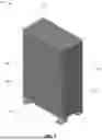
FIG. 1 is a front perspective view of a safety cabinet according to a first embodiment.
FIG. 2 is a front perspective view of the safety cabinet of FIG. 1 in an open position, in accordance with some embodiments.
FIG. 3 is a second front view of the safety cabinet of FIG. 1 in an open position, in accordance with some embodiments.
FIG. 4A is a first isolated perspective view of a first shelf organization accessory of the safety cabinet of FIG. 1, in accordance with some embodiments.
FIG. 4B is a second isolated perspective view of a first shelf organization accessory of the safety cabinet of FIG. 1, in accordance with some embodiments.
FIG. 5A is a first isolated perspective view of a second shelf organization accessory of the safety cabinet of FIG. 1, in accordance with some embodiments.
FIG. 5B is a second isolated perspective view of a second shelf organization accessory of the safety cabinet of FIG. 1, in accordance with some embodiments.
FIG. 6A is a first isolated perspective view of a third shelf organization accessory of the safety cabinet of FIG. 1, in accordance with some embodiments.
FIG. 6B is a second isolated perspective view of a third shelf organization accessory of the safety cabinet of FIG. 1, in accordance with some embodiments.
FIG. 7A is a first isolated perspective view of a fourth shelf organization accessory of the safety cabinet of FIG. 1, in accordance with some embodiments.
FIG. 7B is a second isolated perspective view of a fourth shelf organization accessory of the safety cabinet of FIG. 1, in accordance with some embodiments.
FIG. 8 is a front perspective view of a safety cabinet according to a second embodiment, in accordance with some embodiments.
FIG. 9 is a front perspective view of the safety cabinet of FIG. 8 in an open position, in accordance with some embodiments.
FIG. 10 illustrates one or more flame arresters of the safety cabinet of FIG. 8, in accordance with some embodiments.
FIG. 11 illustrates a self-close mechanism of the safety cabinet of FIG. 8, in accordance with some embodiments.
FIG. 12 illustrates a sump containment of the safety cabinet of FIG. 8, in accordance with some embodiments.
DETAILED DESCRIPTION
Unless the context of their usage unambiguously indicates otherwise, the articles “a,” “an,” and “the” should not be interpreted as meaning “one” or “only one. ” Rather these articles should be interpreted as meaning “at least one” or “one or more. ” Likewise, when the terms “the” or “said” are used to refer to a noun previously introduced by the indefinite article “a” or “an,” “the” and “said” mean “at least one” or “one or more” unless the usage unambiguously indicates otherwise.
It should also be understood that although certain drawings illustrate hardware and software located within particular devices, these depictions are for illustrative purposes only. In some embodiments, the illustrated components may be combined or divided into separate software, firmware and/or hardware. For example, instead of being located within and performed by a single electronic processor, logic and processing may be distributed among multiple electronic processors. Regardless of how they are combined or divided, hardware and software components may be located on the same computing device or may be distributed among different computing devices connected by one or more networks or other suitable communication links.
Thus, in the claims, if an apparatus or system is claimed, for example, as including an electronic processor or other element configured in a certain manner, for example, to make multiple determinations, the claim or claim element should be interpreted as meaning one or more electronic processors (or other element) where any one of the one or more electronic processors (or other element) is configured as claimed, for example, to make some or all of the multiple determinations. To reiterate, those electronic processors and processing may be distributed.
FIGS. 1-3 illustrate an exemplary embodiment of a safety cabinet 100 constructed in for accommodating hazardous and/or flammable materials, in accordance with some embodiments. In some embodiments, the safety cabinet 100 may be constructed of an ultra-violet and/or chemical-resistant material. In other embodiments, the safety cabinet 100 may be painted inside and outside with an ultra-violet and/or chemical resistant paint (for example, a powder-coat paint). The safety cabinet may also be understood as a more traditional cabinet configured for accommodating any type of material or object. The safety cabinet 100 illustrated in FIG. 1 has a generally vertical and rectangular configuration such that the safety cabinet 100 stands upright, as defined by vertical axis A, and is accessible through a forward face. In other embodiments the safety cabinet may have a relatively low, horizontal configuration and may be accessible through a top.
As illustrated, the safety cabinet 100 includes a rear wall 102, a first sidewall 104 extending perpendicularly from the rear wall 102, and a second sidewall 106 extending parallel to the first sidewall 104 and extending perpendicularly from the rear wall 102. The rear wall 102 may be understood as a back of the safety cabinet 100. The first sidewall 104 and the second sidewall 106 may be understood as left and right sides of the safety cabinet 100. The safety cabinet 100 further includes a top wall 108 or ceiling and a bottom wall 110 or floor. The top wall 108 and the bottom wall 110 are joined to, and perpendicular to, the rear wall 102, the first sidewall 104, and the second sidewall 106. The rear wall 102, the first sidewall 104, and the second sidewall 106 are each oriented vertically, parallel to the vertical axis A. The top 108 and the bottom 110 are oriented horizontally, perpendicular to the vertical axis A. Accordingly, the safety cabinet 100 has a substantially rectangular shape. It should be appreciated that the terms “vertical,” “horizontal,” “top,” “bottom,” and the like are for reference purposes only and are not limitations on the disclosure. Additionally or alternatively, the safety cabinet 100 may include additional or non-planar walls to provide different shapes and configurations.
The safety cabinet 100 is supported by a plurality of feet 111 attached to the bottom wall 110. The plurality of feet 111 are arranged on each corner of the bottom wall 110. In the present embodiment, the plurality of feet 111 are substantially trapezoidal in shape. However, in other embodiments, the plurality of feet 111 may have a different shape.
The rear wall 102, the first sidewall 104, the second sidewall 106, the top 108, and the bottom 110 may be constructed of a suitable, fire-resistant material such as steel or aluminum. In other embodiments, alternate structural materials may be used (e.g., plastic, glass, etc.).
The rear wall 102, the first and second sidewalls 104, 106, the top 108, and the bottom 110 provide an enclosure 112 that defines a hollow interior compartment 114. The rear wall 102, the first and second sidewalls 104, 106, the top 108 and the bottom 110 may be flat and relatively planar. The rear wall 102, the first and second sidewalls 104, 106, the top 108 and the bottom 110 may be connected together by any suitable technique, as will be appreciated by one skilled in the art, such by being fixedly joined with fasteners such as bolts or screws, welded together, or joined by adhesives. Fixedly joining the rear wall 102, the first and second sidewalls 104, 106, the top 108 and the bottom 110 together provides a rigid, durable structure that corresponds to the enclosure 112.
The illustrated safety cabinet 100 has a double-walled construction. In particular, each component of the enclosure 112 has a double-walled construction. With continued reference to FIGS. 1-3, the enclosure 112 includes an inner shell 116 and an outer shell 118 to provide a double-walled construction, wherein each outer wall of the outer shell 118 has a corresponding inner wall of the inner shell 116, with the corresponding inner and the outer walls separated by a predetermined distance to define an insulative air space.
For example, the rear wall 102 may be formed of an internal panel and an external panel that are planar, arranged parallel to each other, and are spaced apart from each other to define an air gap there between. The first and second sidewalls 104, 106, the top 108, and the bottom 110 may have a similar double panel construction that defines an air gap between internal and external panels. The air gap may resist the thermal transfer of heat between the internal panel and the external panel. In some embodiments, heat or fire-resistant insulation may be disposed between the internal panel and the external panel.
Forward edges of the first and second sidewalls 104, 106, the top 108, and the bottom 110 form a forward frame 120 that outlines a compartment opening 122 through which access to the interior compartment 114 of the safety cabinet 100 is provided. The forward frame 120, and the corresponding compartment opening 122 defined by the forward frame 120, may be rectangular although other shapes and outlines are contemplated in other embodiments. Additionally, to further seal the interior compartment 114, a compressive seal made of rubber, foam, and/or a similar compressible material may be disposed on the forward frame 120 that the first and second doors 124, 126 may press against when in the closed position.
To close the compartment opening 122 and shut the interior compartment 114, a first door 124 and a second door 126 may be pivotally attached to the forward frame 120 by one or more hinges 128. The hinges 128 may be a continuous hinge that runs along a major portion of the height of the respective door 124, 126 to which it is attached. In other embodiments, a plurality of discrete hinges may be provided along the height of the respective door 124, 126 rather than the continuous, “piano” style hinges 128 illustrated in FIG. 1. Additionally, while the doors 124, 126 and the hinges 128 have a rotational axis that is vertically oriented, in other embodiments, the rotational axis may be aligned horizontally.
When in the closed position, the first and second doors 124, 126 are parallel to and spaced apart from the rear wall 102. To securely contain the contents of the safety cabinet, the first and second doors 124, 126 may include door handles 129 that are operatively associated with a locking mechanism that may operatively interact with the forward frame 120 via sliding dead bolts or the like to prevent unintended opening of the interior compartment 114.
The safety cabinet 100 may include a suitable latch system 171 adapted to help retain the doors 124, 126 in the closed position. In some embodiments, the latch system 171 may be a three-point latch system having various configurations, including a slam-latch style that need not be operated in order to permit the doors 124, 126 to move from an open position to the closed position. In some embodiments, the latch system 171 includes a bullet slam latch 172, first and second latch rod assemblies 173, 174 (see FIG. 3), and the paddle handle 129. The paddle handle 129 is adapted to selectively actuate the latch system 171 to move the distal ends of the latch rod assemblies 173, 174 and the bullet slam latch 172 from an extended position to a retracted position in which the doors 124, 126 may be moved from the closed position to one of a range of open positions. The bullet slam latch 172 and the first and second latch rod assemblies 173, 174 are adapted to bias the latch members to extended positions but also to permit the latch members to move from the extended positions to respective retracted positions in response to the door 124 moving from an open position to the closed position (in other words, when it is “slammed” closed). In some embodiments, the safety cabinet 100 may include means for automatically closing the doors. In such embodiments, the safety cabinet 100 may include actuators (not shown) adapted to urge the first and second doors 124, 126, respectively, to the closed position.
While loading and unloading the safety cabinet 100, it may be desirable that the doors 124, 126 remain in an open position. In such a circumstance, the safety cabinet 100 may include means for selectively retaining the doors 124, 126 in an open position.
In some embodiments, to create a more effective seal, the outer and inner sealing flanges of the first and second doors 124, 126 are arranged such that the inner sealing flange of the second door 126 is disposed in inward relationship to the first door 124, and the outer sealing flange of the first door 124 is disposed in outer relationship to the second door 126.
As illustrated in FIGS. 2-3, one or more shelves 130 may be disposed in the interior compartment 114 to support the contents of the safety cabinet 100. The shelves 130 may be arranged horizontally and may extend between the first sidewall 104 and the second sidewall 106. In addition to the shelves 130, the bottom 110 may function as a lower base shelf onto which items may be set. In some embodiments, to adjust the vertical elevation of the shelves 130, one or more upright supports 132 may be formed in or attached to the first and second sidewalls 104, 106 and may extend generally between the top wall 108 and the bottom wall 110. The upright supports 132 may include a plurality of vertically extending notches 134 that may accommodate clips or brackets on which the horizontal shelves 130 may rest. The upright supports 132 may further include a plurality of hooks 136 configured to be received by corresponding recesses on the horizontal shelves 130. Each of the plurality of hooks 136 may include a first hook portion 137 and a second hook portion 139 extending from the first hook portion 137. The first hook portion 137 extends in a direction perpendicular to the vertical axis A. The second hook portion 139 extends in a direction parallel to the vertical axis A.
In the present embodiment, the safety cabinet 100 includes two upright supports 132a arranged on the first sidewall 104 and two upright supports 132b arranged on the second sidewall 106. Additionally, the safety cabinet 100 includes a plurality of upright supports 132c, 132d arranged on an interior portion of the first door 124 and the second door 126, respectively. More particularly, the plurality of upright supports 132c, 132d are disposed such that the plurality of upright supports 132c, 132d are facing the interior compartment 114 when the doors 124, 126 are in the closed position. The first door 124 includes two upright supports 132c and the second door 126 includes two upright supports 132d.
In the present embodiment, the two upright supports 132c included on the first door 124 are spaced apart by a length L1. Similarly, the two upright supports 132d included on the second door 126 are spaced apart by a length L2. In the present embodiment, the length L1 between the two upright supports 132c is about 37 centimeters. In other embodiments, the length L1 may be between about 30 centimeters and 40 centimeters. Similarly, in the present embodiment, the length L2 between the two upright supports 132d is about 37 centimeters. In other embodiments, the length L2 may be between about 30 centimeters and 40 centimeters.
As illustrated in FIG. 3, the plurality of upright supports 132c, 132d are attached to the doors 124, 126 to support and removably receive several shelf organization accessories 138. In some embodiments, the upright supports 132 may be releasably connected to the doors 124, 126. The plurality of shelf organization accessories 138 are configured to receive and support various safety peripherals (e.g., paint spray cans, caulking tubes, latex glove dispenser, squirt bottle dispensers, etc.). For example, the plurality of hooks 136 may be further configured to be received by corresponding recesses of the plurality of shelf organization accessories 138. As another example, the plurality of vertically extending notches 134 may be further configured to receive corresponding hooks or brackets of the plurality of shelf organization accessories 138. In alternate embodiments, the shelf organization accessories 138a-e may be arranged on, or supported by, a wall mount.
In the present embodiment, the shelf organization accessories 138 include a first accessory 138a, a second accessory 138b, a third accessory 138c, and a fourth accessory 138d. Each of the first accessory 138a, the second accessory 138b, the third accessory 138c, and the fourth accessory 138d may be configured to receive or hold different types or amounts of safety peripherals. Each of the shelf organization accessories 138 may attach to the upright supports 132 in differing, or unique ways. In the present embodiment, the first accessory 138a, the second accessory 138b, and the third accessory 138c are each disposed on or attached to the upright supports 132c of the first door 124. The fourth accessory 138d is disposed on or attached to the upright supports 132d of the second door 126. In alternate embodiments, any of the shelf organization accessories 138a-e may be disposed on or supported by the upright supports 132a arranged on the first sidewall 104, the upright supports 132b arranged on the second sidewall 106, the upright supports 132c arranged on the first door 124, or the upright supports 132d of the second door 126. In other words, any of the shelf organization accessories 138 may be supported by any such suitable upright supports 132a-d. In some embodiments, the shelf organization accessories 138 may be completely removed from the safety cabinet 100 and may instead be removably coupled with external upright supports 132 attached to an external surface (e.g., a wall).
FIGS. 4A-8B illustrate the shelf organization accessories 138a-d and the corresponding upright supports 132 in greater detail. The configuration of the upright supports 132 and the shelf organization accessories 138a-e described herein allow for ease of removability or adjustability. A height, or location, of the shelf organization accessories 138a-e may be adjusted by a user without the use, or need for, a tool.
As shown in FIGS. 4A-4B, the first shelf organization accessory 138a includes a base portion 178 and a basket 180. The base portion 178 is configured to removably engage with the plurality of hooks 136 of the corresponding upright supports 132. The base portion 178 includes a top end 182, a bottom end 184, a first side 183, and a second side 185. The top end 182 includes a first curved segment 186 and the bottom end 184 includes a second curved segment 188. In the illustrated embodiment, the first curved segment 186 is curved in an upside-down u-shape. Additionally, in the illustrated embodiment, the second curved segment 188 is curved in a u-shape. The first curved segment 186 may be shaped and sized to be placed on, or supported by, the second hook portion 139. The base portion 178 further includes a plurality of hook receiving apertures 190 configured to receive one of the plurality of hooks 136. In the present embodiment, the base portion 178 includes two hook receiving apertures 190 vertically aligned on the first side 183 and two hook receiving apertures 190 vertically aligned on the second side 185. In the present embodiment, the hook receiving apertures 190 are spaced to receive vertically adjacent hooks 136. The basket 180 is a receptacle configured to receive and support safety peripherals (for example, but not limited to, latex, or other material, gloves). The basket 180 is substantially rectangular in shape. The top end 182 and the bottom end 184 are spaced apart by a height H1. In the present embodiment, the height H1 between the top end 182 and the bottom end 184 is about 13 centimeters. In other embodiments, the height H1 may be between about 10 centimeters and 15 centimeters.
As shown in FIGS. 5A-5B, the second shelf organization accessory 138b includes a top attachment portion 194, a top side 198, a front side 199, a bottom side 200, and a bottom attachment portion 202. The top attachment portion 194 includes a first curved segment 204 and the bottom attachment portion 202 includes a second curved segment 208. The first curved segment 204 and the second curved segment 208 are both shaped in an upside-down u-shape. Accordingly, the first curved segment 204 and the second curved segment 208 are shaped and sized to be placed on, or supported by, the second hook portion 139. In the present embodiment, the first curved segment 204 and the second curved segment 208 are spaced to be received by non-vertically adjacent hooks 136. In other words, a first hook 136a of the plurality of hooks 136 which receives the first segment 204 is spaced apart from a second hook 136b of the plurality of hooks 136 which receives the second curved segment 208 by a third hook 136c of the plurality of hooks 136 positioned between the first hook 136a and the second hook 136b.
The front side 199 extends perpendicular to and connects the top side 198 and the bottom side 200. The top side 198 includes a plurality of apertures 210 shaped and sized to receive, for example, a cylinder (e.g., a paint spray can). In the illustrated embodiment, the top side 198 includes five (5) apertures 210. Accordingly, the top side 198, the front side 199, and the bottom side 200 form a receiving structure for up to five (5) spray cans, or other safety peripherals of the like. The top side 198 and the bottom side 200 are spaced apart by a height H2. In the present embodiment, the height H2 between the top side 198 and the bottom side 200 is about 12.6 centimeters. In other embodiments, the height H2 may be between about 10 centimeters and 15 centimeters.
As shown in FIGS. 6A-6B, the third shelf organization accessory 138c includes a top attachment portion 212, a top side 214, a front side 216, a bottom side 218, and a bottom attachment portion 220. The top attachment portion 212 includes a first curved segment 222 and the bottom attachment portion 220 includes a second curved segment 224. The first curved segment 222 and the second curved segment 224 are both shaped in an upside-down u-shape. Accordingly, the first curved segment 222 and the second curved segment 224 are shaped and sized to be placed on, or supported by, the second hook portion 139. Similar to the second shelf organization accessory 138b, in the present embodiment, the first curved segment 222 and the second curved segment 224 are spaced to be received by non-vertically adjacent hooks 136. In other words, the first hook 136a of the plurality of hooks 136 which receives the first segment 222 is spaced apart from a second hook 136b of the plurality of hooks 136 which receives the second curved segment 224 by a third hook 136c of the plurality of hooks 136 positioned between the first hook 136a and the second hook 136b.
The front side 216 extends perpendicular to and connects the top side 214 and the bottom side 218. The top side 214 includes a plurality of apertures 226 shaped and sized to receive, for example, a small cylinder (e.g., a caulking tube). In the illustrated embodiment, the top side 214 includes seven (7) apertures 226. Accordingly, the top side 214, the front side 216, and the bottom side 218 form a receiving structure for up to seven (7) safety peripherals. The top side 214 and the bottom side 218 are spaced apart by a height H3. In the present embodiment, the height H3 between the top side 214 and the bottom side 218 is about 15.2 centimeters. In other embodiments, the height H3 may be between about 12 centimeters and 20 centimeters.
As shown in FIGS. 7A-7B, the fourth shelf organization accessory 138d includes a top attachment portion 228, a top side 230, a front side 232, a bottom side 234, and a bottom attachment portion 236. The top attachment portion 228 includes a first curved segment 238 and the bottom attachment portion 236 includes a second curved segment 240. The first curved segment 238 and the second curved segment 240 are both shaped in an upside-down u-shape. Accordingly, the first curved segment 238 and the second curved segment 240 are shaped and sized to be placed on, or supported by, the second hook portion 139. Similar to the second shelf organization accessory 138b and the third shelf organization accessory 138c, in the present embodiment, the first curved segment 238 and the second curved segment 240 are spaced to be received by non-vertically adjacent hooks 136. In other words, the first hook 136a of the plurality of hooks 136 which receives the first segment 238 is spaced apart from a second hook 136b of the plurality of hooks 136 which receives the second curved segment 240 by a third hook 136c of the plurality of hooks 136 positioned between the first hook 136a and the second hook 136b.
The front side 232 extends perpendicular to and connects the top side 230 and the bottom side 234. The top side 230 includes a plurality of apertures 242 shaped and sized to receive, for example, a cylinder (e.g., a paint spray can). In the illustrated embodiment, the top side 230 includes four (4) apertures 242. Accordingly, the top side 230, the front side 232, and the bottom side 234 form a receiving structure for up to four (4) safety peripherals. In the present embodiment, the top side 230 and the bottom side 234 are spaced apart by a height H4. In the present embodiment, the height H3 between the top side 230 and the bottom side 234 is about 15.2 centimeters. In other embodiments, the height H3 may be between about 12 centimeters and 20 centimeters.
FIGS. 8 and 9 illustrate a safety cabinet according to another embodiment of the disclosure. The safety cabinet 300 may be similar to the safety cabinet 100 shown in FIG. 1 and described above. Therefore, like features are identified with like references numerals plus “100”, and only the differences between the two will be discussed.
As shown in FIGS. 8 and 9, the safety cabinet 300 includes a rear wall 302, a first sidewall 304 extending perpendicularly from the rear wall 302, and a second sidewall 306 extending parallel to the first sidewall 304 and extending perpendicularly from the rear wall 302. The rear wall 302 may be understood as a back of the safety cabinet 300. The first sidewall 304 and the second sidewall 306 may be understood as left and right sides of the safety cabinet 300. The safety cabinet 300 further includes a top wall 308 or ceiling and a bottom wall 310 or floor. The top wall 308 and the bottom wall 310 are joined to, and perpendicular to, the rear wall 302, the first sidewall 304, and the second sidewall 306. The rear wall 302, the first sidewall 304, and the second sidewall 306 are each oriented vertically, parallel to the vertical axis A. The top 308 and the bottom 310 are oriented horizontally, perpendicular to the vertical axis A.
The safety cabinet 300 is supported by a plurality of feet 311 attached to the bottom wall 310. The plurality of feet 311 are arranged on each corner of the bottom wall 310. In the present embodiment, the plurality of feet 311 are substantially triangular in shape. However, in other embodiments, the plurality of feet 311 may have a different shape.
As illustrated in FIGS. 9 and 10, in some embodiments the safety cabinet 300 includes one or more flame arresters 315. In some embodiments, a first flame arrester 315a is located proximate the top of the safety cabinet 300, while a second flame arrester 315b is located proximate the bottom of the safety cabinet 300. The flame arresters 315 may be configured to ventilate fumes (including, but not limited to, flammable gases) from within the safety cabinet 300.
As illustrated in FIGS. 9 and 11, in some embodiments, the safety cabinet 300 includes a self-close mechanism 320. The self-close mechanism 320 may be partially contained within the housing of the safety cabinet 300 and configured to provide obstruction-free access to the interior compartment 114 of the safety cabinet 300. In some embodiments, the self-close mechanism 320 is configured to automatically close the first and/or second doors 124.
As illustrated in FIG. 12, in some embodiments, the interior compartment 114 of the safety cabinet 300 includes a containment sump 325 configured to capture and/or contain spills and/or leaks (for example, of a liquid). The containment sump 325 may be approximately 1-inch to approximately 5-inches deep, however in other embodiments, the containment sump 325 may be smaller or larger.
Embodiments provide, among other things, a safety cabinet. Various features and advantages of the application are set forth in the following claims.
Claims
What is claimed is:1. A safety cabinet comprising:
an enclosure defining an interior compartment and a compartment opening, the interior compartment being accessible via the compartment opening;
a door being rotatably mounted to the enclosure and moveable over a range of travel between an open position and a closed position, the door adapted to cover at least a portion of the compartment opening of the enclosure when the door is in the closed position;
a plurality of upright supports arranged on an interior of the door such that the plurality of upright supports face the interior compartment when the door is in the closed position, the upright supports including a plurality of vertically extending notches and a plurality of hooks; and
a plurality of shelf organization accessories configured to receive and support safety peripherals;
wherein the plurality of upright supports are configured to support and removably receive the plurality of shelf organization accessories.
2. The safety cabinet of claim 1, wherein the plurality of upright supports includes two upright supports.
3. The safety cabinet of claim 2, wherein the two upright supports are spaced apart by a length of greater than 30 centimeters.
4. The safety cabinet of claim 1, wherein each of the plurality of hooks includes a first hook portion and a second hook portion extending from the first hook portion.
5. The safety cabinet of claim 4, wherein the plurality of shelf organization accessories includes a first accessory including a base portion and a basket.
6. The safety cabinet of claim 5, wherein the base portion is configured to removably engage with the plurality of hooks.
7. The safety cabinet of claim 6, wherein the base portion includes a plurality of hook receiving apertures, each of the plurality of hook apertures configured to removably receive one of the plurality of hooks.
8. The safety cabinet of claim 4, wherein the plurality of shelf organization accessories includes a second accessory including a top attachment portion, a top side, a front side, and a bottom attachment portion.
9. The safety cabinet of claim 8, wherein the top attachment portion includes a first curved segment, and wherein the bottom attachment portion includes a second curved segment.
10. The safety cabinet of claim 9, wherein the first curved segment and the second curved segment are shaped and sized to be placed on, or supported by, the second hook portion.
11. The safety cabinet of claim 1, further comprising a flame arrester.
12. The safety cabinet of claim 11, wherein the flame arrester is located at at least one selected from a group consisting of a top portion of the safety cabinet and a lower portion of the safety cabinet.
13. The safety cabinet of claim 11, further comprising a second flame arrester.
14. The safety cabinet of claim 13, wherein the flame arrester is located at a top portion of the safety cabinet and the second flame arrester is located at a bottom portion of the safety cabinet.
15. The safety cabinet of claim 1, further comprising a self-close mechanism configured to close the door.
16. The safety cabinet of claim 1, further comprising a containment sump located in a bottom portion of the safety cabinet, wherein the containment sump is configured to contain a liquid.
17. The safety cabinet of claim 16, wherein the containment sump is approximately one-inch to approximately five inches deep.
Images & Drawings included:


Sources:
- United States Patent and Trademark Office - verify current appl. status at the USPTO↗
Similar patent applications:
- » 20180104369
SAFETY CABINET AND METHOD FOR DECONTAMINATING SAFETY CABINET - » 20250189276
CONSTRUCTION ELEMENT FOR A SAFETY CABINET, A DOOR FOR A CONTAINER AND A CONTAINER COMPRISING SUCH A CONSTRUCTION ELEMENT AND A METHOD FOR IMPROVING A SAFETY CABINET - » 10419146
Safety cabinet with safety monitoring system - » 20100213802
Cabinet, in particular safety cabinet - » 20230263302
Fireproof cabinet body structure and fireproof safety cabinet - » 10414221
Remotely operable safety cabinet - » 18800383
Quick-assembly sealed safety cabinet - » 10650820
Safety cabinet for antibiohazard - » 10417075
Revolving gun safety cabinet - » 15982221
Integral positive unlock device for drawer and cabinet safety locks
Recent applications in this class:
- » 20250344851 2025-11-13
RACK SYSTEM AND MODULAR AUDIO EQUIPMENT - » 20250143456 2025-05-08
HAZARDOUS MATERIAL STORAGE SHED SYSTEM - » 20250031846 2025-01-30
Transportable, Storable, Modifiable, Collapsible, Modular, Ball Rack - » 20250024941 2025-01-23
SUBSTRATE LOADING APPARATUS - » 20250017368 2025-01-16
SMART CABINET - » 20250009125 2025-01-09
AUTO-LOADING STORAGE SYSTEM - » 20240268553 2024-08-15
OUTDOOR CABINET - » 20240225274 2024-07-11
STORAGE SYSTEM AND METHOD - » 20240188714 2024-06-13
MOVABLE COFFEE CAPSULE STORAGE RACK - » 20240164518 2024-05-23
Luggage Storage Berth Device