NETWORKS, SYSTEMS AND METHODS FOR WILDFIRE MITIGATION
US20260069904A1
2026-03-12
19/295,519
2025-08-08
Smart Summary: New systems and equipment have been developed to help prevent and control wildfires. They include a control system that manages fire response plans for specific areas. Each parcel of land can be monitored and optimized for fire management. A safety feature ensures that if something goes wrong, the internal fire management system will still work. Additionally, water pumper trucks can supply water to these systems, and there may also be water towers connected to the trucks for extra support. 🚀 TL;DR
Abstract:
There is provided systems, equipment and networks having a control system having an operation control command plan for wild fire and internal fire mitigation and suppression. In embodiments there is provided a parcel by parcel control and optimization of the EFMS and IFMS for a particular area. In embodiments of these systems and methods they have a failsafe valve for operation of IFMS and EFMS, where the default or failsafe is for the operation of the IFMS. In embodiments of these systems and methods they have a water pumper truck feeding water to the EFMS, and can further have water tower system that is feed by the pumper truck.
Assignee:
- HAS LLC 13 🇺🇸 Jackson, WY, United States
Applicant:
Interested in similar patents?
Get notified when new applications in this technology area are published.
Classification:
A62C3/02 » CPC main
Fire prevention, containment or extinguishing specially adapted for particular objects or places for area conflagrations, e.g. forest fires, subterranean fires
A62C37/00 » CPC further
Control of fire-fighting equipment
Description
This application: (i) claims priority to, and under 35 U.S.C. § 119(e)(1) the benefit of, U.S. provisional application Ser. No. 63/680,993 filed Aug. 8, 2024; (ii) is a continuation-in-part of U.S. patent application Ser. No. 18/798,451 filed Aug. 8, 2024; and is a continuation-in-part of U.S. patent application Ser. No. 19/198,036 filed May 3, 2025, the entire disclosure of each of which is incorporated herein by reference.
BACKGROUND OF THE INVENTION
Field of the Invention
The present inventions relate to networks, control systems, and multivariable component systems and activities for the management, mitigation, and suppression of wildfires, and including internal structure fires.
The term “wildfire” as used herein, unless specified otherwise should be given its broadest possible meaning and would include any outdoor fire, and any fire that is located outside of a structure, this would include for example brush fires, forest fires, and grass fires. The term wildfire, however, as used herein, unless specified otherwise, would further include structure fires that were caused directly or indirectly by a wildfire.
As used herein, unless specified otherwise, the terms “external fire management system” (“EFMS”), “external fire suppression system”, “static fire protection system”, “fixed fire protection system”, “structure fire protection system” and similar such terms, should be given their broadest possible meaning, and would include systems that provide a fire suppressant medium (e.g., water) on the outside of structures, to the adjacent grounds and both. The adjacent grounds would include land area, vegetation, and materials located in contact with, adjacent to, near and around the structure, e.g., as far as about 10 feet, about 20 feet, and about 50 feet, from 10 feet to 30 feet, from 5 feet to 75 feet, or more from the exterior walls of the structure. These systems can for example provide water in the form of sprays, mists, streams, sheets and combinations and variations of these to the structures and adjacent grounds. The systems can provide fire suppressant foam to the outside of structures and to the adjacent grounds. These systems can provide combinations of water and foam. These systems can use a fire suppressant medium that is water, foam, or fire retardant and use combinations of two or three of these mediums, either simultaneously, alternatively, or in various patterns, including alternating patterns of use, as well as patterns of use designed to address a specific predetermined conduction (e.g., hydration levels of materials near a structure). These systems can, and typically do have, sensors and monitors, that provide data about the system, its activation, its rate of use of fire suppression medium (e.g., water or foam), the temperature(s) in and around the structure. It is understood that the exterior or outside of the structure includes one or more of the roof, exterior walls, outer surfaces of outside walls, gutters, garage doors, or any portion or part of the structure that is exposed to the outside environment, and thus likely to be exposed to the wildfire and embers. An example of a fixed fire protection system would be those provided by Frontline Fire Protection LLC., in Casper Wyoming.
As used herein, unless specified otherwise, the term “internal fire suppression system” and similar such terms, should be given its broadest possible meaning, and would include any automated sprinkler system or other fire suppression system that is located inside of a structure and configured to manage and suppress a fire that is inside of that structure. Typically, these internal fire suppression systems are static systems.
As used herein, unless specified otherwise, the terms “node”, “communication node”, “point on a network”, “communication point”, “data point”, “network address” and similar such terms are to be given their broadest possible meanings, and would include for example, sensors, processors, data receiving assemblies, data transmitting assemblies, data receiving/processing/transmitting assemblies, GUI, satellite dishes, cable boxes, transmitters, TVs, computers, gaming stations, gps transmitters, cellular devices, cellular phones, tablets, iPhones®, iPad®, I/O (input/output) devices, and data storage devices. A node may also be a structure or location where other nodes may be present, for example a structure with an external fire management system, having its own control network of sensors, activators, cell phone applications, and I/O devices.
As used herein, unless specified otherwise, the term “GUI” (graphic user interface) is to be given its broadest possible meaning and would include for example devices that are fully interactive, partially interactive and not interactive, it would include all types of displays and monitors (both with and without keyboards), it would include touch screen monitors and even heads up displays and Google Glass. Braille devices, and other devices for assisting in and communicating with the visually impaired, or persons with other disabilities, are considered herein to be a GUI.
As used herein, unless specified otherwise, the terms “network”, “network pathway”, “pathway” and similar terms are to be given there broadest meaning and would include any wires, optical, wireless, fibers, light waves, magnetic wave, or other medium over which data can be transmitted, combinations of various types of different types of these mediums, which would include for example, satellite broadcasts, conventional television signals, cable networks, telephone networks, DSL networks, the internet, the world wide web, intranets, private networks, local networks, cellular, Ethernet, node to node links, radio, telegraph, power lines, and other presently known or later developed technologies for transmitting, receiving and/or sharing data and information. By way of example fire retardants can be any material, e.g., chemical composition, that alters the way in which the fire burns, such as by decreasing fire intensity, slowing the advance of the fire, and both. The materials preferably retain their fire retardant properties even after the water originally contained in the material has evaporated. It is understood that the water is primarily used to aid in the uniform distribution of the fire retardant over a predetermined area. Fire retardants can be long-term retardants, pre-treatment retardants and combinations of these, and others. Preferably, the fire retardants fall within the standards set forth by the United States Department of Agriculture, Forest Service Specification FS 5100-304d.
In general, fire retardants contain salts, such as agricultural fertilizers. Fire retardants are available as liquid or dry concentrates that are then mixed with water prior to distribution to a designated area. The subsystem, e.g., 2730, would perform this mixing (of water and concentrate retardant) and provided the mixture to the selector 2740.
Examples of the mix ratio (retardant concentrate to water) for commercially available fire retardants are set forth in Table 3.
| TABLE 3 | ||
| Fire retardant | Mix Ratio | |
| Phos-Chek MVP-Fx | 0.96 | lbs/gal | |
| Phos-Chek MVP-F | 0.95 | lbs/gal | |
| Fortress FR-100 | 1.68 | lbs/gal | |
| Fortress FR-105M | 1.68 | lbs/gal | |
| Phos-Chek 259-Fx | 1.01 | lbs/gal | |
| Phos-Chek LC-95A-R | 5.5:1 | (gal:gal) | |
| Phos-Chek LC-95A-Fx | 5.5:1 | (gal:gal) | |
Phos-Chek MVP-Fx contains 80-90% Monoammonium phosphate (CAS-No. 7722-76-1), 5-10% Diammonium phosphate (CAS-No. 7783-28-0) and less than 15% performance additives.
Phos-Chek MVP-F contains 75-85% Monoammonium phosphate (CAS-No. 7722-76-1), 8-12% Diammonium phosphate (CAS-No. 7783-28-0) and less than 15% performance additives.
In general fire retardants contain materials, such as Aqueous MgCl2 solution, Ammonium polyphosphate solution, Attapulgus clay, Iron oxide, Monoammonium phosphate, Diammonium phosphate, Amorphous silica, and MgCl2. The retardants can contain 70% or more, 75% or more, 80% or more, 85% or more of Aqueous MgCl2 Solution, Ammonium polyphosphate solution, Monoammonium phosphate, Diammonium phosphate, amorphous silica, or MgCl2 as the primary component of the retardant concentrate.
In general the retardant concentrate can be mixed with water in amounts of about 0.6:1 (dry weight lbs: gal water) to about 2.5:1 (lbs/gal); or from about 4:1 (liquid retardant gal: gal water) to about 7:1 liquid retardant gal: gal water).
Generally, the term “about” and the symbol “˜” as used herein, unless specified otherwise, is meant to encompass the greater of a variance or range of +10%, or the experimental or instrument error associated with obtaining the stated value.
As used herein, unless expressly stated otherwise terms such as “at least”, “greater than”, also mean “not less than”,i.e., such terms exclude lower values unless expressly stated otherwise.
As used herein, unless stated otherwise, room temperature is 25° C. And, standard temperature and pressure is 25° C. and 1 atmosphere. Unless expressly stated otherwise all tests, test results, physical properties, and values that are temperature dependent, pressure dependent, or both, are provided at standard temperature and pressure.
As used herein, unless specified otherwise, the recitation of ranges of values, a range, from about “x” to about “y”, and similar such terms and quantifications, serve as merely shorthand methods of referring individually to separate values within the range. Thus, they include each item, feature, value, amount or quantity falling within that range. As used herein, unless specified otherwise, each and all individual points within a range are incorporated into this specification, and are a part of this specification, as if they were individually recited herein.
This Background of the Invention section is intended to introduce various aspects of the art, which may be associated with embodiments of the present inventions. Thus, the foregoing discussion in this section provides a framework for better understanding the present inventions, and is not, and should not be viewed as, an admission of prior art.
SUMMARY
There has been a long-standing, ever-increasing need for systems, networks and methods that can integrate and control methods and systems for wildfire mitigation, management and suppression. This need, among others, includes a longstanding, ever-increasing need for the management and coordination of multiple EFMS, internal fire suppression systems, and both, during a wildfire event. This long standing and ever increasing need is believed to be present across all aspects of wildfire mitigation, management and suppression, including for example: coordination of external fire management systems, coordination of internal fire suppression systems, activation of external fire management systems; activation of internal fire suppression systems, coordination and management of water pressure, or line pressure, management of ingress and egress routes; evacuations, including notices and plans; response team deployment and supplies, to name a few. The present inventions meet these and other needs.
There has been a long-standing, ever-increasing need for systems, networks and methods that can provide for the automated control of interrelated systems and apparatus used for the mitigation, management and suppression of wildfires, and internal structure fires. This long standing and unmet need is believed to be present across all aspects of wildfire and internal structure fire mitigation, management and suppression, including for example: activation of external fire management systems; activation of internal fire management systems, management of available water resource systems, e.g., public water supply, including pressure, flow rate and location, during a fire emergency, and coordination of one or more and all of these systems, to name a few. The present inventions meet these and other needs.
Thus, Thus, there is provided a system for mitigating fire risks, the system having: an external fire management system (EFMS); a graphic user interface (GUI) device; a control system in control communication with the EFMS and the GUI device; the control system having an operation control command plan for performing an operation plan; and, a water pumper truck in fluid communication with the EFMS.
Moreover, there is provided these systems and methods having one or more of the following features: wherein the operation control system is cloud-based; wherein the operation control system is at least in part contained in a local controller for the EFMS; having a hydration plan; having a lockout plan; having two or more of an interlock, a hydration plan, a lockout plan, a low line pressure plan, and an adjacent structure based plan; wherein the auto-activation notice causes the GUI device to display a first screen; wherein the first screen contains the time to activation countdown; wherein the first screen is configured to link to a second screen for display on the GUI device; wherein the second screen has a display for receiving a user input to activate the EFMS immediately; and, wherein the second screen has a display for receiving a user input to deactivate the EFMS immediately.
Still further, there is provided these systems and methods having one or more of the following features: wherein the auto-activation notice with default activation plan is configured to upon a predetermined event: start a time to activation countdown; send an automatic activation notice to the GUI device; and activate the EFMS upon an end of the countdown, unless the control system receives a deactivation instruction.
Additionally, there is provided a system for mitigating fire risks, the system having: an external fire management system (EFMS); a control system in control communication with the EFMS and configured for control communication with a GUI device; the control system having an operation control command plan for performing an operation plan; the operation control command plan for performing an operation plan having an auto-activation notice with default activation plan; and, wherein the auto-activation notice with default activation plan is configured to upon a first event: determine a time to activation; start a countdown to activation based upon the determined time to activation; send a first automatic activation notice to the GUI device; activate the EFMS upon an end of the countdown, unless the control system receives a deactivation instruction from the GUI device; a water pumper truck in fluid communication with the EFMS.
Yet additionally, there is provided these systems and methods having one or more of the following features: wherein the auto-activation notice with default activation plan is configured to upon a second event adjust the time to activation to provide an adjusted countdown; send a second automatic activation notice to the GUI device, based upon the adjusted countdown; and activate the EFMS upon an end of the adjusted countdown, unless the control system receives a deactivation instruction from the GUI device; wherein the auto-activation notice with default activation plan is configured to upon a third event adjust the time to activation to provide a second adjusted countdown; send a third automatic activation notice to the GUI device, based upon the second adjusted countdown; and activate the EFMS upon an end of the second adjusted countdown, unless the control system receives a deactivation instruction from the GUI device; wherein the first even is based upon predictive data; wherein the first even is based upon derived data; wherein the first even is based upon real time data; wherein the first even is based upon at least two of: a location of a wildfire, a wind speed, a hydration levels, a location of smoke, a location of embers, a direction of movement of a wildfire, and a temperature; wherein the time to activation is predetermined; wherein the time to activation is at least 5 minutes; wherein the time to activation is at least 10 minutes; wherein the time to activation is from about 5 minutes to about 15 minutes; wherein the first auto-activation notice causes the GUI device to display a first screen; wherein the first screen contains the time to activation; wherein the first auto-activation notice causes the GUI device to display a first screen; and, wherein the first screen is configured to link to a second screen for display on the GUI device; wherein the second screen has the time to activation and a display for receiving a user input to activate the EFMS immediately; and wherein the first auto-activation notice causes the GUI device to display a first screen; and, wherein the first screen is configured to link to a second screen for display on the GUI device; wherein the second screen has the time to activation and a display for receiving a user input to deactivate the EFMS; and, having two or more of an interlock, a hydration plan, a lockout plan, a low line pressure plan, and an adjacent structure based plan.
Moreover, there is provided a GUI device for mitigating fire risks, the GUI device serving as a node on an emergency management control network and system, the GUI device having: the GUI device in communication with a control system, wherein the control system is a part of the emergency management control network and system; and, the GUI device configured to receive and display a first auto-activation notice; wherein the auto-activation notice is configured to cause the GUI device to display a first auto-activation field on the GUI device; wherein the first auto-activation filed provides a first notice that an external fire management system is set to automatically activate; and, the GUI device configured to receive a status regarding a water pumper truck in fluid communication with an EFMS.
Still further, there is provided a method of operating an external fire management system (EFMS) located at a structure; wherein the EFMS is in control communication with a control system, the control system configured to receive information, send information, and evaluate information; the method having: the control system receiving an event information; the control system, based at least in part upon the event information: (i) configuring the EFMS for automatic activation at an activation time; and (ii) causing a first notice to be transmitted to a GUI device, wherein the GUI device is located a distance from the structure; the GUI device, upon receipt of the first notice, displaying a first message that the EFMS will be automatically activated; automatically activating the EFMS at the activation time, if no user input is provided to the control system; and a water pumper truck in fluid communication with the EFMS.
Still further there is provided the systems or methods of any of the forgoing claims, further having at least one sprinkler tower system.
In addition, there is provided the systems or methods of any of the forgoing claims, wherein the system has a failsafe assembly, having a default configuration to supply a fire suppression material to an interior fire management system (IFMS) and thus not supply the fire suppression material to an EFMS.
Moreover, there is provided a structure having an interior fire management system (IFMS) and an external fire management system (EFMS) system for mitigating fire risks, the system having: a structure first external fire management system (EFMS) associated with a first structure; a control system; a failsafe assembly; wherein the failsafe assembly is in fluid communication with a source of fire suppression material and the EFMS and the IFMS; wherein the failsafe assembly has a default configuration to place the supply the fire suppression material to the IFMS.
Additionally, there is provided these systems and methods having one or more of the following features: wherein the control system is configured to receive an instruction from an emergency management system to activate the lockout plan; wherein the control system is configured to receive an instruction from a user to deactivate the lockout plan; wherein the first event has one or more of: an activation of a first interior sprinkler system at the first structure; an activation of a second interior sprinkler system at a second structure, wherein the second structure is adjacent the first structure; and, an activation of a second EFMS at the second structure, wherein the second structure is adjacent the first structure; wherein the first event has one or more of: an activation of a first interior sprinkler system of the first structure; an activation of a second interior sprinkler system at a second structure; and, an activation of a second EFMS at the second structure; wherein the first event has one or more of a detection of a line pressure at or below a low line pressure limit in a water line feeding the first structure; and, a detection of the line pressure in a water line feeding a second structure; and wherein the fire suppression material is one or more of water, foam or fire retardant.
BRIEF DESCRIPTION OF THE DRAWINGS
FIG. 1A is a schematic of an embodiment of an emergency communications system in accordance with the present inventions.
FIG. 1B is a detailed schematic of an embodiment of a data processing assembly of the system of FIG. 1A, in accordance with the present inventions.
FIG. 2 is a schematic of an embodiment of a EFMS in accordance with the present inventions, which can form a node on embodiments of an emergency communications systems in accordance with the present inventions.
FIG. 3 is a schematic of an embodiment of an EFMS in accordance with the present inventions.
FIG. 3A is a schematic of an embodiment of an EFMS in accordance with the present inventions.
FIG. 3B is a schematic of an embodiment of an EFMS in accordance with the present inventions.
FIG. 3C is a schematic of an embodiment of an in accordance with the present inventions.
DESCRIPTION OF THE PREFERRED EMBODIMENTS
The present inventions, in general, relate to networks, systems and methods for mitigating, managing and address wildfires and risks of wildfire. In general, in embodiments of the present invention there is provided emergency management control network and system, having a control system, that is in control communication with one or more local controllers. In these embodiments, the control system, the local controller and both, have one or more operation control command plan for performing an operation plan. In embodiments, these operation plans can be, one or more of, a hydration plan, a lockout plan, a low line pressure plan, an adjacent structure based plan, and an auto-activation notice with default activation plan.
Embodiments of the present inventions relate to relate to networks, systems and methods for mitigating, managing and address wildfires and risks of wildfire that utilize and interface with components, including software, of irrigation system (e.g., agriculture watering system, lawn sprinklers, etc.) that are typically used for providing water to the land surrounding the structure as a part of the emergency management control network and system. Thus, in these embodiments the irrigation system components become a part of, or are used and controlled by, the external fire management system (EFMS), such as being controlled by the control system for the EFMS, the local controller for the EFMS, or both.
More particularly, in embodiments, the present inventions relate to emergency management control network and systems, having a control system, that is in control communication with one or more local controllers associated with an EFMS. The control system has one or more operation control command plan for performing an operation plan. In embodiments, these operation plans can be, one or more of, a hydration plan, a lockout plan, a low line pressure plan, an adjacent structure based plan, and an auto-activation notice with default activation plan. In embodiments the control system executes, or carries out these various plans based upon raw data, derived data, predictive data, adaptive strategies, virtual data, and combinations and variations of this data.
Embodiments of the present inventions relate to systems, equipment and methods for the monitoring, control and management of hydration levels in the area surrounding a structure for the prevention, mitigation and management of wildfires. In preferred embodiments, the hydration levels are determined, established or maintained for predetermined areas surrounding a structure. Further, embodiments of the present inventions include predetermined hydration plans, including, plans based upon raw data, derived data, predictive data, adaptive strategies, virtual data, and combinations and variations of this data.
Embodiments of the present inventions relate to systems, equipment and methods for the monitoring, control and management of nearby EFMSs and internal fire management systems, in larger areas and smaller areas, including down to adjacent parcels, based upon raw data, derived data, predictive data, adaptive strategies, virtual data, and combinations and variations of this data. surrounding a structure for the prevention, mitigation and management of wildfires.
Embodiments of the present inventions relate to systems, equipment and methods for the monitoring, control and management of peripheral systems to EFMS and an internal fire management system, based upon raw data, derived data, predictive data, adaptive strategies, virtual data, and combinations and variations of this data.
In general, in embodiments of the present invention, the EFMS is part of, or on a network, and receive information, e.g., data, about conditions around and near the structure that EFMS is associated with and protects. This information could come from any number of sources, for example, external moisture or hydration sensors, optical sensors and devices, other EMFSs, emergency networks, user input, first responder input, and water pressure sensors. This information can be provided to the control system, and based upon the algorithms and programing of the control system the control system can shut down a particular EFMS. This embodiment would be a local controller having a lockout program for its specific EFMS.
In general, embodiments of the present systems and methods inventions relate to EFMS and networks having interlocking control systems and methods that control the operation of individual EFMS based upon events and conditions of an entire area or zone of a plurality of EFMSs.
Turning to FIGS. 1A and 1B, there is provided a general example of an embodiment of an emergency communication systems, which is an emergency management control network and system for a geographic area or location, such as a community. The communication system 100, has a network 101. The network 101 may be any type or combination of types of communication and data networks. Thus, for example, the network 101 can be a distributed network, a direct communication network, a control network, the internet, the world wide web, a wireless network, a cellular network, a Wi-Fi network, a hard-wired network, an Ethernet network, a satellite network and combinations and variations of these, and other data and information communicate equipment and process that are presently known and may become known in the future.
The fire emergency communication system 100 has several nodes or communication points, each node or communication point having one or more receiving device, monitoring device, transmitting device and combinations and variations of these. There is a node 110 that is associated with a residential area, e.g., a nodal area. There is a node 105 that is associated with a rural area, e.g., a nodal area. There is a node 103 that is associated with an area having access to a limited access highway, e.g., an intersection nodal area. There is a node 104 that is associated with an urban area, e.g., an urban nodal area. Each of these nodes, also has a number of individual nodes within, or associated with them. The individual nodes within a node, form a nodal area, nodes that are mobile can move from one nodal area to another nodal area.
It is understood, that one, tens, and hundreds of nodal areas, each having one, tens and hundreds of nodes, can be associated with the communication system 100, and network 101. Moreover, multiple networks, such as network 101, can be associated with, or a part of, the communication system 100.
The number and types of nodal areas may vary, from situation to situation, community to community, from public services team/organization to public services team/organization and may vary before, during and after a wildfire.
The number and types of individual nodes, in any given nodal area, may vary, from situation to situation, community to community, from public services team/organization to public services team/organization and may vary before, during and after a wildfire.
In the embodiment of FIG. 1A, the network 101 of fire emergency communication system 100 has as individual nodes: dwelling (house, apartment building, condo building, hotel) 112, dwelling (house, apartment building, condo building, hotel) 114, mobile device (cell phone, On-star, apple watch, etc.) 115, mobile device (cell phone, On-star, apple watch, etc.) 116, First Responder (police, Ambulance, EMS (emergency medical services), Red Cross, National Guard, etc.) 117, school 118, first responder unit 120, fixed location monitoring station, data collection and transmission device (positioned on, e.g., cell town, power line pole, etc.) 121, dwelling (e.g., ranch, etc.) 122, airport 125, first responder 133, fixed location monitoring station, data collection and transmission device (positioned, e.g., on a traffic light, associated with a traffic camera, etc.) 136, cell tower (fixed data collection and transmission device) 137, monitoring station, fixed data collection and transmission device 138, mobile device (cell phone, On-star, apple watch, etc.) 140, Emergency Management (head quarter, command center, etc.) 143, police department 144, fire department 145, Ambulance 146, Hospital 147, business (office, retail shop, restaurant, manufacturing, etc.) 150, traffic camera/red light camera (fixed data collection and transmission device) 151, and fixed data collection and transmission device (e.g., positioned on or with a cell tower 152).
Further these nodes may be viewed as sub-nodes of a larger node. For example, fire emergency communication system 101 could be included as a sub-node in a larger communication network, having one, tens, hundreds of similar fire emergency communications systems.
The individual nodes typically and preferably have GUI. They may have associated keyboards, key pads, touch screens, voice control, etc., and combinations and variations of these. The GUI have displays that among other things have graphics for providing information about traffic, fire location, evacuation, evacuation routes, location of gas stations, location of first responders, as well as, the ability to have user input of real time data, e.g., user location, presence of ambers, visibility, proximity to fire, traffic conditions. Preferably, icons, windows or screens are provided on the GUI by an application (app) that is loaded onto a mobile device, such as a smart phone, tablet or vehicle GPS/navigation system. The GUI may also be configured to provide real time, historic, derived, predictive, and virtual data. The GUI may be configured to have private access on the then network to another node on the network. For example, mobile device 140 may have a private communications path with dwelling 112, enabling mobile device to display real time raw data (e.g., images, temperature) of the conditions around dwelling 112 and send instruction to dwelling 112. For example, to activate a fire suppression system for dwelling 112. The monitoring unit of dwelling 112 may also have a processor, or be in communication (control communication) with the processing system to automatically activate the fire suppression system for dwelling 112, sent notifications to mobile device 140 recommending activation of the fire suppression system for dwelling 112, as well as, sending notice that the fire suppression system has been activated. The notices may also be broadcast over the entire network, only to the area where the node or dwelling is located, only to first responders (e.g., emergency services, fire, police, ambulance etc.) and combinations and variations of these.
The network 101, has several communication pathways. These pathways may be over the same routes, or portions of the network 101, they may share some but not all routes, they may be totally separate, and combinations and variations of these. Each route or pathway may have its own proprietary communication protocol, it may use a publicly available protocol. The protocols may include, but are not limited to CoAP, MQTT, AMQP, WAMP, LORAWAN, LoRa, IPv4, or IPv6. The communication, e.g., the data and information set over the pathway may be encrypted, protected, or otherwise encoded, such that only an intended recipient can receive it, for example a predetermined recipient, e.g., an individual who has taken the necessary steps to rightfully receive information and data from the data processing assembly 139.
Each individual node preferably has the ability to receive and transmit data and information. However, a node only needs the ability to receive or transmit data or information. For example, in some embodiments of monitoring stations they may only transmit data and information.
Turning to the residential area 110, there is shown a schematic representation of an example of a residential area. (The residential area may be a part of, adjacent or far removed from the other areas in the system.) The residential area 110 has street 111. The various node in this area each have communication pathways: dwelling 112 has communication pathway 112a, mobile device 115 has communication pathway 115a, mobile device 116 (which is in dwelling 114) has communication pathway 116a, first responder 117 has communication pathway 117a, school 118 has communication pathway 118a. In addition, dwelling 114 has a private security system that has a communication pathway 114a to a private security provider. As discussed below, such nodes, e.g., 114, can be brought into the system 100, by the private security provider feeding, i.e., providing or transmitting, data and information from its network or customers to the processing system 139.
Turning to the rural area 105, there is shown a schematic representation of an example of a rural area. (The rural area may be a part of, adjacent or far removed from the other areas in the system.) The rural area 110 has winding, narrow country road 107, a large area 108 (shown by dotted line) that contains significant fuel sources for a wildfire, and power lines 106. The various nodes in this area each have communication pathways: first responder unit 120 has communication pathway 120a, monitoring station 121 has communication pathway 121a, dwelling 122 has communication pathway 122a, cell tower fixed data collection and transmission device 137 has communication pathway 137a, and monitoring station 138 has communication pathway 138a. And, airport 125, which is adjacent to residential area 110 and rural area 105 has communication pathway 125a,
Turning to the limited access highway area 103, there is shown a schematic representation of an example of a limited access highway and its surroundings. (The limited access highway area may be a part of, adjacent or far removed from the other areas in the system.) The limited access highway area 103 has a multilane limited access highway 131 having multiple on and off ramps, e.g., 132, and a street 130. The various nodes in this area each have communication pathways: monitoring station 136 has communication pathway 136a, mobile device 140 has communication pathway 140a, and first responder 133 has communication pathway 133a.
Turning to the urban area 104, there is shown a schematic representation of an example of an urban area. (The urban area may be a part of, adjacent or far removed from the other areas in the system.) The urban area 104 has a street 141 that intersects street 142. The various nodes in this area each have communication pathways: traffic camera/red light camera 151 has communication pathway 151a. And a fixed data collection and transmission device (e.g., positioned on or with a cell tower 152) adjacent to the urban area 104, has communication pathway 152a. In addition, business 150 has a private security system that has a communication pathway 150a to a private security provider. As discussed below, such nodes, e.g., 150, can be brought into the system 100, by the private security provider feeding, i.e., providing or transmitting, data and information from its network or customers to the processing system 139.
Emergency Management (head quarter, command center, etc.) 143, has communication pathway 143a, police department 144 has communication pathway 144a, fire department 145 has communication pathway 145a, ambulance service 146 has communication pathway 146a, and hospital 147 has communication pathway 147a.
The network 101 has pathway 102 that connects the network to processing system 139 (as shown in greater detail in FIG. 1B). Here one path way is shown, it being understood that multiple pathways to the processing system 139, multiple processing systems and combinations and variations of these can be used.
The network 100 can have multiple private pathways. For example, a dwelling can have an external fire protection system that has a control system, sensors, actuators and communication pathway. This external fire protection system has a private communication pathway with processing system 139, as well as, with one or more mobile devices that also connect to processing system 139 and directly or through the processing system to the control system of the dwelling's fire protection system. There may be tens, hundreds or more of these private pathways. As the processing system 139 receives more data and information it can determine if recommendations to start a particular dwelling's fire protection system should be sent, or if the command to start the system should be sent. This can also be done on an area by area basis.
Thus, for example, the processing system 139 is receiving real time raw data from multiple nodes in the network that provide real time information about, for example traffic patterns, location of fire, speed of fire, direction of movement of the fire, wind speed and direction, humidity, number and location of persons, location of first responders. The processing system 139 also has access to historic data, such as prior weather, prior fire patterns, prior traffic patterns, surveys of fuel sources for the fire, and geographic terrain. The processing system using the real time raw data, and preferably, but not necessarily, the historic data can provide derived data about fire movement, traffic patterns, resource allocation, preferably this derived data can be predictive data. Different forms, and types of this derived data and predictive data can then be transmitted out onto the network to different nodes. For example, the information a mobile device may receive could be limited to the status of a fire suppressions system linked to that device, the proximity of the fire, the predicted path of the fire, traffic and suggested evacuation routes. The information provided to first responders and emergency management HQ could be far more extensive. For example, historic data about the number of dwellings having external fire suppression systems in a particular area, the fuel sources in that area, coupled with real time raw data about the number of people in that area, could be used to determine the placement of first responders, and the need for evacuations.
Nodes, nodal areas, individual nodes may be organized and configured into various sub-nodes. These sub-nodes can be private or semi-private or public. For example, a company could have a private sub-node for its employees, and within that a sub-node for its fleet of vehicles. Similarly, a school could have a sub-node for its children and parents. A sub-node could include all of the nodes that are external fire management systems, and then have sub-nodes for particular types of system, e.g., by provider, level of services, etc.
Turning to FIG. 1B, there is shown a schematic of an embodiment of a data processing system or assembly 139. The data processing system 139 has a network 190 that provides communication pathways to the components of the data processing system 139. The data processing system has a network 190 for transferring information and data between the various components. Incoming information, from pathways 191, 192, 193, is received by unit 194. Pathways 191, 192 and 193 are other sources of raw data, historic data and even predictive and derived data. Processor 195, which may be a computer, has the algorithms and programs to provide the derived data and predictive information, as well as, provide adaptive responsive strategies. Processor 195 also preferably controls the network traffic with and between storage devices 196, 197, 198 and unit 199. Unit 199 is for sending and receiving information to and from the network 101. It should be understood that system 139 may itself be distributed over a network, or reside on the cloud. Unit 194 and 199 may be the same unit, or they may be multiple separate or distributed units, and combinations and variations of these.
Unit 199 receives and provides information, data and control communication to and from the data processing system 190 to the network 101. Data to individuals is sent along pathways 180 for standard data and content, and along path 181 for premium data and content. For example, standard data may show only public service announcements and other official information from the authorities. Premium data, can show predicted fire movement, number and location of external fire management systems (and their status over time).
Both of these individual data streams, sets or packets, e.g., data for individuals, travels along pathway 102 of network 101. This data for individuals travels along pathway 102 to a smart phone, tablet, such as an iPad®, a GUI in an automobile (dash display), or other GUI, where one or more of raw data, derived data, adaptive strategy information and predictive data are presented on the display. Thus, for example, data may travel along pathway 181 to pathway 102 to one or more individual pathways (e.g., 113a) or to a nodal area, e.g., 110, or the entire network. The data is then displayed on the GUI associated with the node (e.g., 113) and information may be input into the GUI and then transmitted along the individual pathway to the network pathway 102, to a pathway, e.g., 181.
The other pathways from unit 199, e.g., pathway 182, 184, 186, etc., are for other custom or special communication or sub-networks. Thus, by way of example, pathway 182 can be for controlled communication for external fire management systems. Realtime raw data, derived data, adaptive strategy information and predictive data may be sent to a user's mobile node, a fixed node on the external fire management system and both. The user can then monitor the information and elect to send a command to the external fire management system to, for example, become read, to operate, or to operate upon a certain set of conditions. The system 139 can send predictive data, e.g., recommending that the external fire management system is activated. The system 139 can also send information, data, or a command to one or more external fire management systems that cause the system(s) to operate.
In this manner the system 139 can provide derived data and adaptive strategies, to individuals and entire areas, in a direct response to changing fire conditions. This provides the ability to save fire suppression resources (i.e., water, foam) until they are absolutely needed, to use them in the most efficient manner, both on a micro level (each individual system, or structure) and on a macho level, (most efficient use of systems, and activation/operation strategy to protect an area).
By way of example, pathway 184 can be non-public and exclusive to fire response teams. Pathway 185 can be non-pubic and exclusive to all first responders. Pathway 183 is for communication with network television and social media. This pathway allows specified data and information from the system 139 to be broadcast to a GUI 186, e.g., a TV or computer monitor, on public networks and social medial.
Generally, the sources for incoming raw data for use in, or to form a basis for, the algorithms and mathematical computations that a processor performs to provide derived data and predictive information and adaptive strategies, can come from various sources, including for example: individual mobile devices (e.g., input from persons, first responders, emergency services, satellites), fixed monitoring devices (e.g., cell tower mounted devices, external fire suppression system, fire services, weather services, traffic monitors, first responders, emergency services, etc.).
Because of the complexity and unpredictability of wild fires, fire emergency and the reactions of persons, although a single approach may be used, in an embodiment a multi-approach system approach is used, the multi-approach having two, three, four or more approaches performed at the same time to determine a set of approach values for a given event at a given point in the fire emergency. These approach values, e.g., probability of event occurring, are then given weightings based upon their individual accuracy for a particular point in the fire emergency, e.g., rural fire, fire size, population levels, population density in relation to ingress and egress routes, start (activation) of an external fire management system, number of EFMSs in a location, etc. The weighted approach values are then combined to provide a predicted value, i.e, derived data of a predictive nature, such as for example an adaptive strategy, a recommendation to activate a particular EFMS, a warning to evacuate, etc.
Turning to FIG. 2 there is shown a schematic of a general embodiment of an EFMS 500. The controller 580 is connected to the network of a fire emergency communications system by one of two or both path ways, i.e., cellular and WiFi to home internet. One, two, ten or more structures in an area can have these EFMS 500. The network can have EFMS of other configurations as well, such as the types generally provided in this Specification. The EFMS can include a manifold 510, a foam system 520, a tie in 530, a pump kit 540, a point of connection 550, a satellite antenna 581, an solar kit 482, and a UPS (universal power supply). These components are associated with a structure (e.g., a house) 560. The system can also have a GUI that is wall mounted or otherwise located at the structure, the GUI is in control communication with the controller 580 and also can be in control communication with a remote GUI, as well as other nodes on a network.
The controller 580 can be in control communication with an operation control command plan (e.g., a determined, including a predetermined, course of action based upon certain inputs, data or both). These control commands can reside entirely in the controller 590 (e.g., the memory associated with the controller and be executed by the processor in the controller), they can reside in a control system in the cloud and be executed by a cloud-based processor, they can be distributed between the cloud and the controller 580, i.e., between the cloud-based control system and the local controller.
In general, the EMFS 500 can be a node on a fire emergency communication system, like system 100, and these fire emergency communication systems can have 5, 10, tens, hundreds, thousands of EFMS as nodes on the system.
The control commands, including the operation control command plans, can be updated, deleted, replaced and managed, for example, via the cloud, via the network, locally and combinations and variations of these.
In general, a control system sends control commands to activate and operate the EMFS, sends commands to a local controller 580 to activate and operate the EMFS and combinations and variations of these depending upon the network and controller configuration. These control commands, among other things, start and stop the operation of the EMFS, thus these commands determine, among other things, the number of cycles, time between cycles, duration of a cycle, as the operation control command plan is carried out through the operation of the EFMS. The stop commands, e.g., deactivate and stop operation of the EFMS, lockout the EFMS, can be based upon a timer, monitored hydration levels, communications from a control system, a GUI, or another notice on the network, as well as, other factors.
Internal fire suppression systems, such as the type having interior sprinkler heads that are activated upon the detection of condition indicating a fire, e.g., increased heat, smoke, can be a node on the network, they can be in communication with an EMFS, either directly (e.g., local controller to local controller), through a GUI, through a control system (e.g., cloud or network controller), and combinations and variations of these, as well as, other control communications configurations. The internal fire suppression systems, would directly protect interior walls, and floors, as well as, furniture, appliances and occupants (such as to facilitate evacuation from the effective structure or room, or to assist in fighting the interior fire).
Generally, the EFMS is in control communication with a control system that has control commands. These control commands can be as simple as an activation signal, a valve open or shut signal, and include more complex or detailed control commands. These more detailed control commands include an operation control command plan for performing an operation plan, such as a hydration plan, a lockout plan, a low line pressure plan, an auto-activation notice with default activation plan, an adjacent structure based plan, etc. These control commands can reside: entirely in local controllers (e.g., data storage and memory associated with a controller at an EFMS of a structure and be executed by the processor in that controller); they can reside in the cloud (e.g., storage and memory associated with a cloud-based controller and be executed by a cloud-based processor); they can reside on the GUI, or, they can be distributed between the cloud, the GUI, the local controllers and combinations and variations of these configurations. In general, the control commands, e.g., the operation control command plans, are programs having, or based upon, algorithms, for executing the operation of the systems, including particular operation plans. The operation control command plan provides for the system to operate and implement an operation plan. The operation plan can be any of the types of plans, disclosed or suggested in is specification, such as a hydration plan, a lockout plan, a low line pressure plan, an auto-activation notice with default activation plan, and an adjacent structure based plan. The operation control command plan can be any multi-operation or multi-step plan for operating the EFMS, the internal fire suppression system and both. The operation control command plan can be based upon data, information and user input, such as, hydration levels, cycle times, wetting rates, fire risk, wind speed and direction, adjacent systems status, other systems status, an activation command, water line pressure, etc.
In embodiments the control system is configured to interface, and thus be in control communication, with the control system for an irrigation system. These irrigation systems can be any system for providing water to agriculture, e.g., lawn, plants, trees, vegetation near or around a structure or in a particular area. Typically, these irrigation systems have a network of pipes or tubing that is connected to a series of sprinklers, or other water distribution devices. Typically, these irrigation systems have a controller that is capable of being a node on a network, or otherwise capable of being in control communication with other devices, such as embodiments of the present control system, e.g., a cloud based control system. If, however, the controller for the irrigation system does not have communication capabilities, it can be modified to provide such capabilities. Such modification includes the addition of a cellular, WiFI or hard wire (e.g., ethernet) communication device. In general, the irrigation system will already be installed at a structure (e.g., a preexisting irrigation system), prior to the installation of the EFMS. However, it is to be understood, that both systems could be installed at the same time (e.g., with new construction) or the EFMS may be installed first with the irrigation system being added later. Thus, in an embodiment the local controller from the EFMS, the control system for the EFMS, or both, are in control communication with the irrigation system. In this manner the water supply, the tubing and the sprinklers of the irrigation system can be specifically used for wildfire mitigation and management. In particular, in an embodiment, the water supply, the tubing and the sprinklers of the irrigation system, can be used, controlled by the operation control command plan for performing an operation plan, of the EFMS, to perform the operation plan.
In an embodiment of the present control system, the control system is configured to have the ability to be control communication with different types of local controllers. These local controllers can be for an EFMS, an irrigation system, an internal sprinkler system, an HVAC system, a security system, a lighting system or other systems. In addition to being configured for communication with these different types of local controllers, the control system is configured for communication with different types of communication protocols, e.g., as used by different manufactures, for each of these different types of systems. Thus, the control system can be configured to be capable of control communication with one, two, three, four, five or more different types of systems. Further, for each of these different types of systems, the control system can be configured to be in control communication with one, two, three or more different communication protocols. In an embodiment, the control system has one or menus, e.g., a series of menus, that are presented on a GUI to guide a user to select predetermined configurations to establish such control communications, and in this manner connect the local controller to the control system.
The control system sends control commands to activate and operate the EMFS, sends commands to a local controller to activate and operate the EMFS and combinations and variations of these depending upon the network and controller configuration. The control system, in some embodiments, can also send control commands to activate and operate internal fire suppression system, sends commands to a local controller to activate and operate the internal fire suppression system and combinations and variations of these depending upon the network and controller configuration. The control commands, among other things, start and stop the operation of the EMFS, thus these commands determine, among other things, the number of cycles, time between cycles, duration of a cycle, as the hydration plan is carried out through the operation of the EFMS. The stop commands (e.g., deactivate and stop operation of the EFMS, and lockout the EFMS), can be based upon a timer, monitored hydration levels, the status of hydration levels of areas and locations, the status of fire suppression systems, internal to a structure and external to the structure, (e.g., armed, operating, standby, available water pressure, etc.) and the water pressure or line pressure of areas and locations., as well as, other factors.
In general, embodiments of the EMFS can be made up, in whole or in part, of irrigation system components; and in particular, one or more of: the water line into the irrigation system, the manifolds or distribution headers for the irrigation system, the tubing or piping connecting the irrigation system to the water distribution devices, e.g., sprinkler heads, the local controller for the irrigation system, and the water distribution devices, e.g., sprinkler heads, for the irrigation system.
In a general, embodiments of an EMFS can have hydration plan control commands, for carry out the hydration plan, the EMFS can have and can receive input from devices that directly or indirectly monitor the hydration levels of combustible materials in predetermined areas, i.e., zones, that surround the structure. The devices for monitoring the hydration levels of combustible materials, can include for example: soil moisture sensors; moisture sensors on, or in, vegetation; visual sensors (e.g., color of vegetation); humidity sensors; temperature sensors; data input, memory and processors that can predilect or determine hydration levels and hydration trends, and combinations and variations of these and other devices. The zones are primarily configured based upon a predetermined distance from the structure. The zones may also be configured based upon natural fire breaks, fire risk and other geographic or environmental factors.
In an embodiment, enhancements in speed can be achieved by inter controller communication on the network. For example, one controller can let another controller know that it has activated, and if a second controller lets other controllers know it has been activated, then there is logic that can be applied to activate the controller receiving the activate information. The communication path for communicating between controllers does not need to be via the cloud, but rather through radio communication, such as a LoRa type system, including LoRaWAN®. FIG. 8 provides a schematic of an example of an architecture for LoRa type system. In an embodiment this architecture is deployed in a star-of-stars topology in which gateways relay messages between end-devices and a central network server. The gateways are connected to the network server via standard IP connections and act as a transparent bridge, simply converting RF packets to IP packets and vice versa. The wireless communication takes advantage of the Long Range characteristics of the LoRaO physical layer, allowing a single-hop link between the end-device and one or many gateways. All modes are capable of bi-directional communication, and there is support for multicast addressing groups to make efficient use of spectrum during tasks such as Firmware Over-The-Air (FOTA) upgrades or other mass distribution messages.
An emergency management control network and system, e.g., the embodiment of FIG. 1, can have one, two, five, tens, hundreds and more EFMS that are on the emergency management control network and system. The network can have EFMS of the types generally show in this Specification, as well as other configurations. The data processing assembly (e.g., 139), based upon raw data received from various nodes on the network, processes that raw data to provide predictive information about the location and movement of a wildfire. The predictive information is communicated over the network. The predictive information can be a control command to a particular EFMS system, such as to arm, to operate, and to stop operations. This control command information can be sent to a group of EFMS in a nodal area, e.g., a predetermined nodal area.
Examples of factors that the control system, the local controller or both may consider (e.g., the computer code, program or algorithm in the control command operation plan for performing an operation plan, such as a lock out plan, an interlock plan, or others, evaluates these factors using a processor and memory). This consideration in a preferred embodiment is conducted a balancing of the factors, based upon the risk or benefits presented by the presence or absence of various factors. In this manner the control system balances these factors as part of a multivariable component systems and activities for the management, mitigation, and suppression of wildfires. For example, these factors would include:
-
- Hydration levels.
- Water line pressure.
- Status of internal fire suppression systems.
- Status of the EFMS in an adjacent structure, and status of the EFMS in further away or more distance structures.
- Status of internal fire suppression systems in an adjacent structure, and status of the internal fire suppression system in further away or more distant structures.
- Status of peripheral systems, such as HVAC, lighting, security systems.
- Increased hydration (e.g., at or above the level wetting that won't burn) of the area immediately around the first structure supports a lock out of the system.
- Water pressure of the incoming water line falling below a pressure that is required for the operation of first responder's fire fighting equipment, supports a lock out of the system. If the pressure falls below a critical level, this factor may mandate a lock out, regardless of the other factors.
- Operation of adjacent EFMSs and EFMSs that are located between the first structure and an active fire supports a lock out of the system.
- Low hydration levels (e.g., dry conditions) around the first structure weighs against a lock out of the system.
- A low number of, or the absence of any, EMFSs adjacent to or between the first structure and active fire weighs against a lock out of the system.
- The proximity of the first structure to an evacuation route, e.g., the first structure is adjacent to, or on, an evacuation route, weighs against a lock out of the system.
- The direction of the wind, moving the fire toward the first structure, weighs against a lock out of the system.
- The activation of the EFMS in one or more adjacent or nearby structures.
- The activation of an internal fire suppression system in one or more adjacent or nearby structures.
- The detection of embers, by the EFMS, or by an EFMS in an adjacent structure, and by an EFMS in further away or more distance structures.
- The activation of EFMS, an interior sprinkler system, or both, in structures directly adjacent to the first structure supports a lockout of the first structure's system, as the first structure will receive a cooling effect from the operation of the adjacent EFMSs.
- The activation of interior fire sprinkler systems of the first structure supports a lockout of the system, this will assure that the internal system has sufficient water to operate properly.
- The duration of time after that an adjacent structure EFMS, interior fire suppression system or both remains operation, could weigh in favor of lifting a lockout.
- The detection of off gassing (which is a precursor to ignition) from materials in an area around the structure, by the EFMS at an adjacent structure, or by the EFMS at structure further away from the first structure.
The balancing of these and other factors can be based upon several factors, such as public policy, emergency management plans, rules or ordnances (state, local or federal), establish industry guidelines, and the capacity and nature of local infrastructure, e.g., the capabilities of the public water system.
The lock out of a system preferably is only for a limited time, and the lockout will be automatically lifted by the control system, the local controller or both, as conditions change, or the balance of the factors change. Further, the control system for the network of EFMSs can be configures so that the balancing of these factors takes place across an entire area, e.g, 10 Structures with EFMSs, 100 Structures with EFMSs, 500 Structures with EFMSs, 1,000 Structures with EFMSs, 2,000 Structures with EFMSs, and 10,000 structures with EFMSs. The network control system can thus, turn on and turn off individual EFMS based, at least in part upon, the received information and data and the predetermined balancing of these different factors.
Once the determination to lock out a particular EFMS is made by the control system, the control system automatically sends a control command to that EFMS, causing the local controller to lock out that system.
Preferably, the control system that makes these determinations, is based in the cloud. This control system can then send and receive control communication and information or data from the local controllers associated with each EFMS, as well as, external sensors, and other inputs, e.g., first responder, users, emergency management authorities.
The lock out could also be limited to switching the EFMS to an alternative water source, such a tank, fire truck, water tanker (e.g., truck, skid mounted container, rail car) or swimming pool.
In embodiments the individual user, e.g., the owner or residence of a structure, receives notices that the EFMS may be locked out, the likely time to such lock out, and that the EFMS is locked out. The user will also receive notice that the lockout has been lifted. (Note, preferably the control system having the lock out program, has or is associated with a control system having one or more of features of the systems in this Specification.) Under certain conditions, and based upon policy, rules and regulations, the user may have the capability to override a lock out command from the control system. In other conditions, this user override capability may not be available, e.g., water line pressure drops below a critical level determined for example by emergency management services or a local or state agency.
It is understood that the embodiments of the Figures, as well as the various examples, and their components, can be used in whole or in part, with each other and with systems having an operation control command plan for performing an operation plan. The operation plan, for example, can be one or more of a hydration plan, a lockout plan, a low line pressure plan, an auto-activation notice with default activation plan, and an adjacent structure based plan. Further, these systems and components can be in communication with, and control communication with, one or more internal fire suppression systems.
EXAMPLES
The following Examples are provided to illustrate various embodiments of systems, devices, methods, and uses of the present inventions. These Examples are for illustrative purposes, may be prophetic, and should not be view as, and do not otherwise limit the scope of the present inventions.
Example 1
As part of the control commands for one or more EFMSs, the commands include an auto-activation notice with default activation plan (“auto-activation plan”). In general, this control command plan is configured to operate generally with three steps. 1) Upon an event (e.g., the detection of an initial threat from a wild fire, a determination of a risk factor, a change in a risk factor, etc.) the control system sends an automatic activation notice to one or more GUIs, the automatic activation notice includes a notice providing a time to activation. 2) The time to activation is counted down by the control system. 3) If the control system has not received an instruction to not activate the system by the end of the time to activation, e.g., the end of the countdown, the system will activate. The operation control command plan for the EMFS, can also include one or more of a hydration plan, a lockout plan, a low line pressure plan, and an adjacent structure based plan. In this manner one or more of these plans can be implement upon automatic activation.
Example 2
In an embodiment of an EFMS having an interlock, the control system is configured so that when an automatic activation notice is sent to a GUI, the system also provides a notice regarding the interlock. Thus, in conjunction with, or as a part of the automatic activation notice, the system sends an interlock notice, advising that one or more other systems associated with the structure will be subject to an interlock operation, such as being shut down, turned off, turned on, or otherwise controlled in a specific manner. The timing (e.g., count down timer) for this interlock operation (e.g., shut down, etc.) can be the same as timer for the automatic activation of the EFMS, or it can be shorter (i.e., interlock operation occurs before automatic activation) or longer (interlock operation occurs at a predetermined time after automatic activation).
The interlock notice, preferably is initially displayed on the GUI as a popup notice with an associated detailed event screen. The lockout popup notice can be a part of the autoactivation notice, or a separate popup. Additionally, the interlock countdown can change with the auto-activation countdown, or can change independently of the auto-activation countdown.
One or more system of the other systems can have separate interlock countdowns. Thus, the interlock countdown for the shutdown of the lawn sprinklers can be different from the interlock countdown for the shutdown of the natural gas.
The user has the ability to manually override the interlock, e.g., the automatic shutdown of the other systems, from the GUI device. However, and preferably, if there is no user input, the shutdown of the other systems will occur at the end of the interlock countdown, as determined by the system.
Example 3
A network and one or more EFMS on the network have a control command operation plan for performing an operation lockout plan. Turning to FIG. 3 there are shown three structures 100, 200, 300 each having an EFMS, and an internal sprinkler system. The structures receive their water from a public water line 400 flowing in the direct of the arrow. Each structure has its own water line 410, 420, 430 extending from line 400 and thus providing a source of water to the structure, and in particular, the EFMS and the internal sprinkler systems. Water lines 410, 420 and 430 each have a sensor 411, 421, 431, which can be a pressure sensor, a flow meter, or both, and water line 400 has a sensor 401, which can be a pressure sensor, flow meter or both. The internal sprinkler systems have sensors 412, 422, 432, which can be pressure sensors, flow sensors, or other means to determine that the system is operating. The EFMS have external sensors, e.g., 413, 423, 433, that determine or sense the moisture/hydration level of the combustible materials adjacent to and near by the structure.
In operation, information from one or more than one, and preferably all of the sensors 401, 411, 421, 431, 412, 422, 432, 413, 423, 433 are transmitted over a network to the cloud-based control system, having the control program that determines if the lock out of a system is needed. (As noted above, the control system can reside on the cloud, the control system can be local, the control system can be distributed between local and cloud systems and combinations and variation of these) Thus, for example the control system could lock out the EFMS for structure 200, if the EFMS system for structure 100, structure 300 or both were operating. Similarly, the controller could lock out the EFMS for any of the structures if the internal system was operating, and in particular if the internal system was operating and the line pressure for the incoming water was low, e.g., below a predetermined pressure to require shut down to the EFMS, when the internal system is operating.
Example 4
In an embodiment, the control command operation plan for performing an operation lockout plan, e.g., the lockout program, resides entirely on the local controller for the EFMS.
Example 5
In an embodiment one or more of an EFMS, the network, or both have a control command operation plan for performing a low line pressure plan, e.g., the lockout is based at least in part upon water line pressure. In an embodiment of the low line pressure plan the network and one or more EFMS on the network have a control command operation plan for performing an operation lockout plan that is based primarily upon water pressure in one or more the water lines feeding a structure, or zone or area of structures. By primarily, it is meant that this factor is most significant, or most heavily weighted in the algorithm. In an embodiment of the low line pressure plan the water pressure in the water line is the only factor relied upon by command operation plan for performing an operation lockout plan.
Example 6
In embodiments the control system has several control command operation plans and methods that can be used to activate the EFMS and control and regulate the operation of EFMS in several operation plans. These embodiments include one or more of the following, as well as, combinations and variations of these.
-
- Moisture sensors are located in the area adjacent to the structure. The moisture sensors send data to the control system that can be used to cause the activation of the EMFS. That data can also be used to send notifications to users, providing moisture levels, recommendations to activate, recommendation to change the EFMS's hydration plan, the fire mitigation plan (exterior sprinkler operation when fire is imminent) or both.
- In an embodiment, the data and the information from the moisture sensors are evaluated by the control system in combination with line pressure of water lines feeding the structures. In this manner, the control system can adjust the hydration plan based upon moisture levels and line pressure, can lock out a system or area if moisture levels are high and line pressure is low, or can evaluate moisture levels in a predetermined area and line pressure in that predetermined area, and optimize EFMS to maximize line pressure (e.g., maintain line pressure at highest levels possible while obtaining effective mitigation of wildfire for the predetermined area).
- In an embodiment, the data and the information from the motion sensors are evaluated by the control system in combination with line pressure of water lines feeding the structures. This monitoring can be on a structure-by-structure basis and for a predetermined area. The information about moisture levels and line pressure is provided to Fire Departments or other emergency management offices, and based upon the information, (including recommendations from the control system) specific EFMS can be locked out.
- In an embodiment the operation of interior sprinkler systems (e.g., NPA13 D systems) is configured to be operated in conjunction with an EFMS. Thus, for example, the activation of the interior sprinkler system can cause the exterior system to lock out. This lock out operation can be based upon line pressure in the interior system, indicating operation of the interior system, and sending a lock out signal to the EFMS. In a preferred embodiment, upon activation of the interior system the control system monitors the line pressure in the interior system, as well as, the line pressure feeding the structure, and in embodiments, also the line pressure feeding a predetermined area where the structure is located. The control system can then make the determinations, based upon one or more of the line pressure in the interior sprinkler, the line pressure feeding the structure, the line pressure in the area, as well as, moisture levels, to lock out the EFMS. In addition to only a lock out option, the control system can modify the hydration plan, the fire mitigation plan (exterior sprinkler operation when fire is imminent) or both for the EFMS.
- In an embodiment the control system can monitor and determine the advantage of the cooling effect to adjacent structures when the interior system is activated in a structure. This can also be an effect from the EFMS being activated in the adjacent structure. The control system can use this cooling effect to adjust, lock out, and regulate the EFMS in the adjacent structures.
- In an embodiment there can be a flow sensor on the internal sprinkler system that determines when the system is operating. This information and data about the activation and operation of the interior systems can be sent wirelessly, (e.g., cellular, satellite) or via wired internet connection to a control system that then can make calculations, determination and provide notice and instructions based upon this information. Thus, for example, the control system can provide instruction to the EFMS, notice to the structure owner, Emergency Management or both.
- In an embodiment the sensor that determines activation of the interior system operates with the EFMS along the lines of a dead man switch. Thus, the sensor sends a signal that permits the EFMS to operate when the interior system is not operating, upon operation of the interior system this signal stops, and thus locks out the EFMS.
Example 7
In an embodiment the EFMS and the interior system are configured to a value or valve assembly (e.g., 3-way value) that is connected to the incoming source of fire suppression material (e.g., water, foam, retardant). This valve is configured to function as a mechanical, or mechanical electric, failsafe device that defaults to supply fire mitigation material (e.g., water, foam, retardant) to the interior system. Thus, if power is lost, control signals are lost, etc., the value would default to and thus provide a source of fire mitigation material (e.g., water) to the interior system. Further, in an embodiment the value can be configure to prioritize the internal system, and once the interior system is activated, not change to the EFMS. Thus, assuring a supply of fire mitigation material to the interior system. In an embodiment, embodiment the value can be configure to prioritize the external system, and once the external system is activated, not change to the EFMS.
Example 8
In an embodiment of these systems that use the existing irrigation systems for piping and sprinkler heads of the EFMS, there can be a foam general system that is also used. The foam generation systems can be in fluid communication (e.g., pipes) with the sprinkler systems and having valves (e.g., cut offs, automatic valves) that permit the foam system to generate foam and flow the foam through the lawn sprinkler heads. Thus, for example only the controller for EFMS can be used and configured to by-pass or turn off the power the landscape irrigation system (e.g., law sprinklers) controller and then operate the landscape irrigation system as an EFMS. In an embodiment both the EMFS controller and manifold are integrated into the landscape irrigation system. The manifold connects below landscape irrigation valves and the EFMS controller turns off power to landscape irrigation controller so that the landscape irrigation valves do not open.
Example 9
Embodiments of the EFMS, including any of the Examples, are reconfigured and adapted for use with, as a part of, or integrated with, an internal fire suppress systems for the protection of the interior of structures. These internal systems can be integrated with, and preferrable are a part of the distributed network of EMFS. The internal systems may rely upon the same source of fire mitigation material as the EMFS for the structure or they may have a completely separate source. Further, there may be a common back up source of fire suppression material that can be used, if needed, by both the EMFS and internal system.
The internal systems can similarly provide and receive information, communication and control communication from users, e.g., home owner, emergency management personal.
Example 10
In an embodiment of this parcel-by-parcel control system, the control system evaluates, the status of EFMSs and internal fire suppression systems at the parcel level, a with respect to each parcel. This evaluation includes an evaluation that a parcel does not have, or is not known to have, an EFMS, an internal fire suppression system or both. The control system, using an operation control command plan, determines the optimum EFMS and peripheral system unitization strategy and status (e.g., activate, locked out, vents open, automatic activation notice, etc.) on a parcel by parcel, PIN by PIN, level, and upgrades this parcel by parcel, PIN by PIN, utilization strategy, periodically, as new information, events and factors are received. Preferably, this updating is continuous.
Example 11
Turning to FIG. 3A there is shown a schematic of an embodiment of the system of Example 3, like numbers have like meanings. In the embodiment of FIG. 3A a pumper water truck 480 is connected by line 483, to a fixed line 481 by way of value and connector 482. The pumper water truck can be for example: a fire truck, a water tanker truck with pumps, a skid mounted water tank with pumps, or a rail car with pumps. The pumps for the water holding vehicle or skid, are preferably on or a part of the truck or vehicle or skid. The pumps however can be provided as a separate unit. The fixed line 481 can be, for example, a fire hydrant.
In this embodiment the pumper water truck is used to supply water under pressure to line 400. In this manner these EFMS, the interior systems and preferably both, for all three structures 100, 200, 300, have sufficient water flow and pressure to be operated effectively.
Although a single water pumper truck 480 is shown, it is to be understood that multiple truck can be used, and can be connected to the same line 481 (e.g., hydrant), or to other lines (e.g., hydrants).
Example 12
Turning to FIG. 3B there is shown a schematic of an embodiment of the system of Example 3, like numbers have like meanings. In the embodiment of FIG. 3B a pumper water truck 480 is connected by line 483, to line 481 by way of value and connector 482. The pumper water truck can be for example: a fire truck, a water tanker truck with pumps, a skid mounted water tank with pumps, or a rail car with pumps. The pumps for the water holding vehicle or skid, are preferably on or a part of the truck or vehicle or skid. The pumps however can be provided as a separate unit.
Line 481 and line 484 can be fixed, e.g., in ground, or can be temporary, and combinations of these. In a preferred embodiment line 481 is a fixed line and connector 482 is of the type found on a conventional fire hydrant, and line 484 is fixed and buried under the ground.
In this embodiment the pumper water truck is used to supply water under pressure to line 484. In this embodiment line 481 does not feed, or otherwise connect to, line 400. Line 484 provides water to the EFMS, the internal sprinkler systems, and preferably both. In an embodiment (not shown in the figure) line 484 connects directly to line 410, 420 and 430, before those lines enter the structures. In this manner the EFMS, the interior systems and preferably both, for all three structures 100, 200, 300, have sufficient water flow and pressure to be operated effectively.
Although a single water pumper truck 480 is shown, it is to be understood that multiple truck can be used, and can be connected to the same line 481, or to other lines.
Example 13
Turning to FIG. 3C there is shown a schematic of an embodiment of the system of Example 3, like numbers have like meanings. In the embodiment of FIG. 3B a pumper water truck 480 is connected by line 483, to a line 481 by way of value and connector 482. The pumper water truck can be for example: a fire truck, a water tanker truck with pumps, a skid mounted water tank with pumps, or a rail car with pumps. The pumps for the water holding vehicle or skid, are preferably on or a part of the truck or vehicle or skid. The pumps however can be provided as a separate unit. The line 481 and connector 482 can be of a type that is generally configured like a conventional fire hydrant, including the same type of connectors.
In this embodiment the pumper water truck is used to supply water under pressure to line 493. In this embodiment line 481 does not feed line 400. Line 403 connects to line 493a and 493b. Lines 493a and 493b are connect to a sprinkler tower systems 490, 491 (e.g., fixed, portable, mobile) respectively. In this manner the tower systems have sufficient water flow, pressure and areas of coverage, to be operated effectively for all three structures 100, 200, 300. Line 493c would be for a third sprinkler tower system not shown. The third sprinkler tower system could be used to provide protection to additional structures, also not shown, or provide additional protection to one or more of structures 100, 200 or 300.
Although a single water pumper truck 480 is shown, it is to be understood that multiple truck can be used, and can be connected to the same line 481 (e.g., hydrant), or to other lines (e.g., hydrants).
Example 15
The systems of Examples 3, 11, 12 and 13, can be cut off from or otherwise disconnected from, or not connected to the network. In these situation, the local control systems with the pumper water truck can be operated manually.
Example 16
The embodiments the forgoing examples may be used with and in combination with each other. For instance, the embodiments and components of the embodiments of Examples 3, 11 to 15 can be used with each other. Similarly, the embodiments and components of the embodiments of Examples 2 to 10 can be used with, or as a part of, the embodiments of Examples 3, 11 to 15.
Example 17
The embodiment of FIG. 3C can be configured to be operated by a local control system that can be cloud based, or based on an EMS server. In this configuration one, two, three or more, ten, ten or more pumper trucks (each with its respective sprinkler towers) are configured in an area at risk for fire. This group of pumper-truck-tower-systems can be controlled by a firefighter at the area, or remotely. Each of these pumper-truck-tower-systems can have one, two, three or more sprinkler tower systems associated with each pumper truck. This configuration greatly reduces the number of firefighting personnel that are need to be on the ground in the area at risk. For example, if one or two firefighters are need for each pumper truck, depending upon the size and number of sprinkler tower systems for each pumper truck, the configuration can reduce the number of firefighters needed to effectively protect the area at risk by 5 or more, 6 or more 7 or more, 10 or more, from 5 to 12, and fewer or greater numbers.
Thus, it is believed that each embodiment of the configuration of the pumper-truck-tower-systems (e.g., FIG. 3A), is equal to 3 to 12 fire fighter equivalents, 4 to 7 fire fighter equivalents, 5 to 10 firefighter equivalents. A firefighter equivalent is the number of firefights that are no longer necessary, and thus replaced by the pumper-truck-tower-systems, to safely and effectively provide the same level of fire protection for a specific area.
Thus, these pumper-truck-tower-systems can be a significant force multiplier, and also greatly reduce the risks to fire fighters.
It is noted that there is no requirement to provide or address the theory underlying the novel and groundbreaking performance or other beneficial features and properties that are the subject of, or associated with, embodiments of the present inventions. Nevertheless, various theories are provided in this specification to further advance the art in this important area, and in particular in the important area of lasers, laser processing and laser applications. These theories put forth in this specification, and unless expressly stated otherwise, in no way limit, restrict or narrow the scope of protection to be afforded the claimed inventions. These theories many not be required or practiced to utilize the present inventions. It is further understood that the present inventions may lead to new, and heretofore unknown theories to explain the operation, function and features of embodiments of the methods, articles, materials, devices and system of the present inventions; and such later developed theories shall not limit the scope of protection afforded the present inventions.
The various embodiments of networks, systems for providing and displaying data and information set forth in this specification may be used in the above identified fields and in various other fields. Additionally, these embodiments, for example, may be used with: existing networks, emergency systems, social media systems, alert systems, broadcast systems, as well as other existing equipment; future systems and activities; and such items that may be modified, in-part, based on the teachings of this specification. Further, the various embodiments set forth in this specification may be used with each other in different and various combinations. Thus, for example, the configurations provided in the various embodiments of this specification may be used with each other. For example, the components of an embodiment having A, A′ and B and the components of an embodiment having A″, C and D can be used with each other in various combinations, e.g., A, C, D, and A. A″ C and D, etc., in accordance with the teaching of this Specification. The scope of protection afforded the present inventions should not be limited to a particular embodiment, configuration or arrangement that is set forth in a particular embodiment, example, or in an embodiment in a particular Figure.
The invention may be embodied in other forms than those specifically disclosed herein without departing from its spirit or essential characteristics. The described embodiments are to be considered in all respects only as illustrative and not restrictive.
Claims
1. A system for mitigating fire risks, the system comprising:
a. an external fire management system (EFMS);
b. a graphic user interface (GUI) device;
c. a control system in control communication with the EFMS and the GUI device;
d. the control system comprising an operation control command plan for performing an operation plan; and,
e. a water pumper truck in fluid communication with the EFMS.
2. The system of claim 1, wherein the operation control system is cloud-based.
3. The system of claim 1, wherein the operation control system is at least in part contained in a local controller for the EFMS.
4. The system of claim 1, comprising a hydration plan.
5. The system of claim 1, comprising a lockout plan.
6. The system of claim 1, comprising two or more of an interlock, a hydration plan, a lockout plan, a low line pressure plan, and an adjacent structure based plan.
7. The system of claim 1, wherein the auto-activation notice with default activation plan is configured to upon a predetermined event:
a. start a time to activation countdown;
b. send an automatic activation notice to the GUI device;
c. activate the EFMS upon an end of the countdown, unless the control system receives a deactivation instruction.
8. The system of claim 7, wherein the auto-activation notice causes the GUI device to display a first screen; wherein the first screen contains the time to activation countdown.
9. The system of claim 8, wherein the first screen is configured to link to a second screen for display on the GUI device; wherein the second screen comprises a display for receiving a user input to activate the EFMS immediately.
10. The system of claim 9, wherein the second screen comprises a display for receiving a user input to deactivate the EFMS immediately.
11. A system for mitigating fire risks, the system comprising:
a. an external fire management system (EFMS);
b. a control system in control communication with the EFMS and configured for control communication with a GUI device;
c. the control system comprising an operation control command plan for performing an operation plan;
d. the operation control command plan for performing an operation plan comprising an auto-activation notice with default activation plan; and,
e. wherein the auto-activation notice with default activation plan is configured to upon a first event:
i. determine a time to activation;
ii. start a countdown to activation based upon the determined time to activation;
iii. send a first automatic activation notice to the GUI device;
iv. activate the EFMS upon an end of the countdown, unless the control system receives a deactivation instruction from the GUI device
f. a water pumper truck in fluid communication with the EFMS.
12. The system of claim 11, wherein the auto-activation notice with default activation plan is configured to upon a second event adjust the time to activation to provide an adjusted countdown; send a second automatic activation notice to the GUI device, based upon the adjusted countdown; and activate the EFMS upon an end of the adjusted countdown, unless the control system receives a deactivation instruction from the GUI device.
13. The system of claim 12, wherein the auto-activation notice with default activation plan is configured to upon a third event adjust the time to activation to provide a second adjusted countdown; send a third automatic activation notice to the GUI device, based upon the second adjusted countdown; and activate the EFMS upon an end of the second adjusted countdown, unless the control system receives a deactivation instruction from the GUI device.
14. (canceled)
15. (canceled)
16. (canceled)
17. The system of claim 11, wherein the first even is based upon at least two of: a location of a wildfire, a wind speed, a hydration levels, a location of smoke, a location of embers, a direction of movement of a wildfire, and a temperature.
18. The system of claim 11, wherein the time to activation is predetermined.
19. The system of claim 11, wherein the time to activation is at least 5 minutes.
20. The system of claim 11, wherein the time to activation is at least 10 minutes.
21. (canceled)
22. The system of claim 11, wherein the first auto-activation notice causes the GUI device to display a first screen; wherein the first screen contains the time to activation.
23. The system of claim 11, wherein the first auto-activation notice causes the GUI device to display a first screen; and, wherein the first screen is configured to link to a second screen for display on the GUI device; wherein the second screen comprises the time to activation and a display for receiving a user input to activate the EFMS immediately.
24. The system of claim 11, wherein the first auto-activation notice causes the GUI device to display a first screen; and, wherein the first screen is configured to link to a second screen for display on the GUI device; wherein the second screen comprises the time to activation and a display for receiving a user input to deactivate the EFMS.
25. (canceled)
26. (canceled)
27. The system of claim 11, comprising a hydration plan.
28. (canceled)
29. The system of claim 11, comprising two or more of an interlock, a hydration plan, a lockout plan, a low line pressure plan, and an adjacent structure based plan.
30. A GUI device for mitigating fire risks, the GUI device serving as a node on an emergency management control network and system, the GUI device comprising:
a. the GUI device in communication with a control system, wherein the control system is a part of the emergency management control network and system; and,
b. the GUI device configured to receive and display a first auto-activation notice;
c, wherein the auto-activation notice is configured to cause the GUI device to display a first auto-activation field on the GUI device;
d, wherein the first auto-activation filed provides a first notice that an external fire management system is set to automatically activate; and,
e. the GUI device configured to receive a status regarding a water pumper truck in fluid communication with an EFMS.
31. (canceled)
32. (canceled)
33. (canceled)
34. The GUI device of claim 30, wherein the first auto-activation field is linked to a second auto-activation field, and the first, the second or both auto-activation fields display a time to activation.
35. (canceled)
36. (canceled)
37. (canceled)
38. The GUI device of claim 30, wherein the first auto-activation field is linked to a second auto-activation field, and the first, the second or both auto-activation fields display a time to activation, a field for receiving a user input to deactivate the EFMS and a field for receiving a user input to activate the EFMS immediately.
39. (canceled)
40. (canceled)
41. (canceled)
42. A method of operating an external fire management system (EFMS) located at a structure; wherein the EFMS is in control communication with a control system, the control system configured to receive information, send information, and evaluate information; the method comprising:
a. the control system receiving an event information;
b. the control system, based at least in part upon the event information: (i) configuring the EFMS for automatic activation at an activation time; and (ii) causing a first notice to be transmitted to a GUI device, wherein the GUI device is located a distance from the structure;
c. the GUI device, upon receipt of the first notice, displaying a first message that the EFMS will be automatically activated;
d. automatically activating the EFMS at the activation time, if no user input is provided to the control system; and
e. a water pumper truck in fluid communication with the EFMS.
43-68. (canceled)
69. A structure having an interior fire management system (IFMS) and an external fire management system (EFMS) system for mitigating fire risks, the system comprising:
a. a structure first external fire management system (EFMS) associated with a first structure;
b. a control system;
c. a failsafe assembly;
d, wherein the failsafe assembly is in fluid communication with a source of fire suppression material and the EFMS and the IFMS;
e, wherein the failsafe assembly has a default configuration to place the supply the fire suppression material to the IFMS.
70-74. (canceled)
Images & Drawings included:

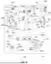

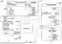

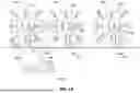
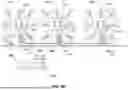
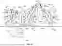
Sources:
- United States Patent and Trademark Office - verify current appl. status at the USPTO↗
Similar patent applications:
- » 20240216727
NETWORKS, SYSTEMS AND METHODS FOR WILDFIRE MITIGATION - » 20240212467
NETWORKS, SYSTEMS AND METHODS FOR WILDFIRE MITIGATION - » 20240216736
NETWORKS, SYSTEMS AND METHODS FOR WILDFIRE MITIGATION - » 20250177793
NETWORKS, SYSTEMS AND METHODS FOR WILDFIRE MITIGATION - » 20260038352
NETWORKS, SYSTEMS AND METHODS FOR ENHANCED WILDFIRE MITIGATION, PROTECTION AND SUPPRESSION - » 20230186744
NETWORKS, SYSTEMS AND METHODS FOR ENHANCED WILDFIRE MITIGATION, PROTECTION AND SUPPRESSION - » 20230293924
NETWORKS, SYSTEMS AND METHODS HAVING A HYDRATION PLAN CONTROL SYSTEM FOR WILDFIRE MITIGATION
Recent applications in this class:
- » 20260054110 2026-02-26
CATASTROPHIC WILDFIRE INDEX FOR FORECASTING UTILITY-CAUSED WILDFIRES - » 20250082971 2025-03-13
ADVANCED WILDFIRE IGNITION PREVENTION AND NOTIFICATION - » 20240382787 2024-11-21
MULTI-FUNCTIONAL ROBOTIC SYSTEM FOR CONTROLLING FIRE EXTINCTION AT INDUSTRIAL SITES - » 20240335687 2024-10-10
Chine-Backed Flame Diverter for Rocket Systems - » 20240216727 2024-07-04
NETWORKS, SYSTEMS AND METHODS FOR WILDFIRE MITIGATION - » 20230347193 2023-11-02
SYSTEMS AND METHODS FOR MINIMIZING WILDFIRE IGNITION RISK - » 20230347192 2023-11-02
Fire suppression system and firefighting aircraft having the same - » 20230271041 2023-08-31
Spray Module and Device Method For Fighting a Vegetation Fire - » 20230091027 2023-03-23
DISTRIBUTED WASTEWATER COLLECTION, TREATMENT AND REUSE SYSTEM WITH INTEGRATED, INTELLIGENT WILDFIRE DEFENSE - » 20210016117 2021-01-21
WILD FIRE PREVENTION APPARATUS
Recent applications for this Assignee:
- » 20260038352 2026-02-05
NETWORKS, SYSTEMS AND METHODS FOR ENHANCED WILDFIRE MITIGATION, PROTECTION AND SUPPRESSION - » 20250269213 2025-08-28
COMMUNITY FIRE MANAGEMENT METHODS AND SYSTEMS - » 20250222294 2025-07-10
OPEN CONNECTIVITY EMERGENCY MANAGEMENT SYSTEMS FOR WILDFIRE MITIGATION - » 20250177793 2025-06-05
NETWORKS, SYSTEMS AND METHODS FOR WILDFIRE MITIGATION - » 20240216736 2024-07-04
NETWORKS, SYSTEMS AND METHODS FOR WILDFIRE MITIGATION - » 20240216727 2024-07-04
NETWORKS, SYSTEMS AND METHODS FOR WILDFIRE MITIGATION - » 20240212467 2024-06-27
NETWORKS, SYSTEMS AND METHODS FOR WILDFIRE MITIGATION - » 20240017103 2024-01-18
AUTOMATED WILDFIRE PREVENTION AND PROTECTION SYSTEM FOR DWELLINGS, BUILDINGS, STRUCTURES AND PROPERTY - » 20230293924 2023-09-21
NETWORKS, SYSTEMS AND METHODS HAVING A HYDRATION PLAN CONTROL SYSTEM FOR WILDFIRE MITIGATION - » 20230186744 2023-06-15
NETWORKS, SYSTEMS AND METHODS FOR ENHANCED WILDFIRE MITIGATION, PROTECTION AND SUPPRESSION