ROLL PRESS APPARATUS AND METHOD FOR MANUFACTURING PROCESSED PRODUCT
US20260070109A1
2026-03-12
19/323,621
2025-09-09
Smart Summary: A roll press apparatus is designed to shape materials using two rolls. It has a sensor that checks if the rolls are bending or deflecting. When the sensor detects this bending, a control unit adjusts the rolls to counteract the deflection. This helps maintain the correct shape of the rolls during the manufacturing process. Overall, the system ensures better quality and consistency in the products being made. 🚀 TL;DR
Abstract:
A roll press apparatus includes a sensor unit configured to measure shapes of a first roll and a second roll to detect deflection of the first roll and the second roll, and a control unit configured to, in response to detection of the deflection by the sensor unit, operate at least one of a first bending unit and a second bending unit such that a counter-deflection is applied to the first roll and the second roll.
Inventors:
- Kyoji FURUKAWA 1 🇯🇵 Aichi, Japan
- Shogo Nakajima 1 🇯🇵 Aichi, Japan
- Nariyuki Okanami 1 🇯🇵 Aichi, Japan
Assignee:
- SINTOKOGIO, LTD. 219 🇯🇵 Nagoya-shi, Japan
Applicant:
Interested in similar patents?
Get notified when new applications in this technology area are published.
Classification:
B21B37/28 » CPC main
Control devices or methods specially adapted for metal-rolling mills or the work produced thereby Control of flatness or profile during rolling of strip, sheets or plates
Description
CROSS-REFERENCE TO RELATED APPLICATION
This application is based on Japanese Patent Application No. 2024-157384 filed with Japan Patent Office on Sep. 11, 2024, the entire contents of which are hereby incorporated by reference.
TECHNICAL FIELD
The present disclosure relates to a roll press apparatus and a method for manufacturing a processed product.
BACKGROUND
International Publication No. 2020/100561 discloses a roll press apparatus. This apparatus includes a sensor provided downstream of a pair of rolls to detect a thickness of a workpiece. The thickness of the workpiece is detected at three or more points in a width direction of the workpiece. Based on the thickness measurement values at the three or more points and a target thickness value, this apparatus adjusts deflection of the rolls and a distance between the rolls such that the thickness in the width direction of the workpiece becomes uniform and reaches the target value.
SUMMARY
In the apparatus described in International Publication No. 2020/100561, since the first roll and the second roll are adjusted based on the thickness of the workpiece after a roll press process, there is a risk that a workpiece with a non-uniform thickness in the width direction may flow at least to a position where the sensor is located. The present disclosure provides a technology capable of reducing an amount (length) of generation of a workpiece having a non-uniform thickness in the width direction.
A roll press apparatus according to one aspect of the present disclosure includes: a first roll having a first rotation shaft and a second roll having a second rotation shaft, configured to sandwich a workpiece being conveyed; a first bearing and a second bearing provided at respective ends of the first rotation shaft; a third bearing and a fourth bearing provided at respective ends of the second rotation shaft, the third bearing facing the first bearing, and the fourth bearing facing the second bearing; a first bending bearing and a second bending bearing provided at respective ends of the first rotation shaft, the first bending bearing being located outside of the first bearing, and the second bending bearing being located outside of the second bearing; a third bending bearing and a fourth bending bearing provided at respective ends of the second rotation shaft, the third bending bearing being located outside of the third bearing and facing the first bending bearing, and the fourth bending bearing being located outside of the fourth bearing and facing the second bending bearing; a first pressurizing unit configured to apply a load to at least one of the first bearing and the third bearing in a direction in which the first roll and the second roll move toward each other; a second pressurizing unit configured to apply a load to at least one of the second bearing and the fourth bearing in a direction in which the first roll and the second roll move toward each other; a first bending unit configured to apply a load to the first bending bearing and the third bending bearing in a direction in which the first roll and the second roll move toward or away from each other; a second bending unit configured to apply a load to the second bending bearing and the fourth bending bearing in a direction in which the first roll and the second roll move toward or away from each other; a sensor unit configured to measure shapes of the first roll and the second roll to detect deflection of the first roll and the second roll; and a control unit configured to, in response to detection of the deflection by the sensor unit, operate at least one of the first bending unit and the second bending unit such that a counter-deflection is applied to the first roll and the second roll.
A method for manufacturing a processed product according to another aspect of the present disclosure is a method for manufacturing a processed product using a roll press apparatus, the roll press apparatus includes: a first roll having a first rotation shaft and a second roll having a second rotation shaft, configured to sandwich a workpiece being conveyed; a first bearing and a second bearing provided at respective ends of the first rotation shaft; a third bearing and a fourth bearing provided at respective ends of the second rotation shaft, the third bearing facing the first bearing, and the fourth bearing facing the second bearing; a first bending bearing and a second bending bearing provided at respective ends of the first rotation shaft, the first bending bearing being located outside of the first bearing, and the second bending bearing being located outside of the second bearing; a third bending bearing and a fourth bending bearing provided at respective ends of the second rotation shaft, the third bending bearing being located outside of the third bearing and facing the first bending bearing, and the fourth bending bearing being located outside of the fourth bearing and facing the second bending bearing; a first pressurizing unit configured to apply a load to at least one of the first bearing and the third bearing in a direction in which the first roll and the second roll move toward each other; a second pressurizing unit configured to apply a load to at least one of the second bearing and the fourth bearing in a direction in which the first roll and the second roll move toward each other; a first bending unit configured to apply a load to the first bending bearing and the third bending bearing in a direction in which the first roll and the second roll move toward or away from each other; a second bending unit configured to apply a load to the second bending bearing and the fourth bending bearing in a direction in which the first roll and the second roll move toward or away from each other; and a sensor unit configured to measure shapes of the first roll and the second roll to detect deflection of the first roll and the second roll, the method includes: determining whether or not the deflection has been detected by the sensor unit; and operating at least one of the first bending unit and the second bending unit such that a counter-deflection is applied to the first roll and the second roll in response to detection of the deflection by the sensor unit.
According to the present disclosure, it is possible to reduce an amount of generation of a workpiece having a non-uniform thickness in the width direction.
BRIEF DESCRIPTION OF THE DRAWINGS
FIG. 1 is a front view showing an example of a roll press apparatus according to an embodiment.
FIG. 2 is a right side view showing an example of the roll press apparatus of FIG. 1.
FIG. 3 is a top view showing an example of the roll press apparatus of FIG. 1.
FIG. 4 is a perspective view showing an example of the roll press apparatus of FIG. 1.
FIG. 5 is a schematic diagram for explaining an arrangement position of sensors.
FIG. 6 is a schematic diagram for explaining deflection control of the roll press apparatus.
FIG. 7 is a schematic diagram for explaining thickness control of the roll press apparatus.
FIGS. 8A, 8B and 8C are schematic diagrams for explaining a procedure for measuring deflection of the roll press apparatus.
FIG. 9 is a flowchart showing an operation for controlling deflection of the rolls.
FIG. 10 is a flowchart showing an operation for controlling a thickness of a workpiece.
DETAILED DESCRIPTION
Hereinafter, embodiments of the present disclosure will be described in detail with reference to the drawings. In the description of the drawings, the same elements are denoted by the same reference numerals, and redundant descriptions are omitted. The dimensional ratios in the drawings do not necessarily match those in the description. The words “upper,” “lower,” “left,” and “right” are based on the illustrated state and are used for convenience.
[Configuration of Roll Press Apparatus]
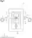
FIG. 1 is a front view showing an example of a roll press apparatus according to an embodiment. FIG. 2 is a right side view showing an example of the roll press apparatus of FIG. 1. FIG. 3 is a top view showing an example of the roll press apparatus of FIG. 1. FIG. 4 is a perspective view showing an example of the roll press apparatus of FIG. 1. In the drawings, an X direction and a Y direction are horizontal directions, and a Z direction is a vertical direction. Hereinafter, the Z direction is also referred to as the up-down direction.
The roll press apparatus 1 shown in FIGS. 1 to 4 is an apparatus that sandwiches a workpiece W being conveyed, and rolls and compresses the workpiece W. The workpiece W is plate-shaped and is made of metal, resin, cloth, or the like. The workpiece W is, for example, a material for an electrode of a secondary battery, a material for an electrode of a fuel cell, a flexible printed circuit board, a component-embedded substrate, a ceramic green sheet, a functional multilayer film, or the like.
As shown in FIGS. 1 to 4, the roll press apparatus 1 has an upper roll 2 (an example of a first roll) and a lower roll 3 (an example of a second roll). The upper roll 2 and the lower roll 3 are arranged to face each other. A workpiece W is fed out from an unwinding shaft 4 and sandwiched between the upper roll 2 and the lower roll 3. The rolled and compressed workpiece W is wound onto a winding shaft 5. In this way, a roll-shaped workpiece W is continuously fed into the roll press apparatus 1, and is rolled and compressed.
The upper roll 2 has an upper rotation shaft 20. A first main bearing 21 (an example of a first bearing) and a second main bearing 22 (an example of a second bearing) are provided at respective ends of the upper rotation shaft 20. The first main bearing 21 and the second main bearing 22 rotatably support the upper rotation shaft 20. The first main bearing 21 and the second main bearing 22 are fixedly supported by a main body frame 6.
The lower roll 3 has a lower rotation shaft 30. A third main bearing 31 (an example of a third bearing) and a fourth main bearing 32 (an example of a fourth bearing) are provided at respective ends of the lower rotation shaft 30. The third main bearing 31 and the fourth main bearing 32 rotatably support the lower rotation shaft 30. The third main bearing 31 faces the first main bearing 21 in the vertical direction. The fourth main bearing 32 faces the second main bearing 22 in the vertical direction.
The third main bearing 31 is supported by the main body frame 6 via a first pressurizing cylinder 41 (an example of a first pressurizing unit). Hereinafter, in the drawings, the cylinders are indicated by arrow shapes, and a direction and a magnitude of a load are indicated by a direction and a length of the arrow shapes. The fourth main bearing 32 is supported by the main body frame 6 via a second pressurizing cylinder 42 (an example of a second pressurizing unit).
The first pressurizing cylinder 41 and the second pressurizing cylinder 42 are devices that apply a load to the third main bearing 31 and the fourth main bearing 32 in a direction in which the upper roll 2 and the lower roll 3 move toward each other. The first pressurizing cylinder 41 and the second pressurizing cylinder 42 are, for example, electric cylinders or hydraulic cylinders. By operation of the first pressurizing cylinder 41 and the second pressurizing cylinder 42, a gap distance between the upper roll 2 and the lower roll 3 is adjusted, and a thickness of the workpiece W and an inclination of the thickness of the workpiece W in the width direction are adjusted.
Furthermore, a first bending bearing 23 and a second bending bearing 24 are provided at respective ends of the upper rotation shaft 20. The first bending bearing 23 and the second bending bearing 24 rotatably support the upper rotation shaft 20. The first bending bearing 23 is located outside of the first main bearing 21. The second bending bearing 24 is located outside of the second main bearing 22.
Furthermore, a third bending bearing 33 and a fourth bending bearing 34 are provided at respective ends of the lower rotation shaft 30. The third bending bearing 33 and the fourth bending bearing 34 rotatably support the lower rotation shaft 30. The third bending bearing 33 is located outside of the third main bearing 31. The third bending bearing 33 faces the first bending bearing 23 in the vertical direction. The fourth bending bearing 34 is located outside of the fourth main bearing 32. The fourth bending bearing 34 faces the second bending bearing 24 in the vertical direction.
Between the first bending bearing 23 and the third bending bearing 33, a first bending cylinder 51 (an example of a first bending unit) is provided that applies a load to the first bending bearing 23 and the third bending bearing 33 in a direction in which the upper roll 2 and the lower roll 3 move toward or away from each other. The first bending cylinder 51 is, for example, an electric cylinder or a hydraulic cylinder. The first bending cylinder 51 is connected to the first bending bearing 23 and the third bending bearing 33, and is configured to push them apart or pull them together. Note that, instead of the first bending cylinder 51, a cylinder (an example of a first bending unit) that pulls up or pushes down the first bending bearing 23 from above and a cylinder (an example of a first bending unit) that pushes down or pushes up the third bending bearing 33 from below may be provided. Alternatively, in addition to the first bending cylinder 51, the plurality of cylinders described above may be provided.
Between the second bending bearing 24 and the fourth bending bearing 34, a second bending cylinder 52 (an example of a second bending unit) is provided that applies a load to the second bending bearing 24 and the fourth bending bearing 34 in a direction in which the upper roll 2 and the lower roll 3 move toward or away from each other. The second bending cylinder 52 is, for example, an electric cylinder or a hydraulic cylinder. The second bending cylinder 52 is connected to the second bending bearing 24 and the fourth bending bearing 34, and is configured to push them apart or pull them together. Note that, instead of the second bending cylinder 52, a cylinder (an example of a second bending unit) that pulls up or pushes down the second bending bearing 24 from above and a cylinder (an example of a second bending unit) that pushes down or pushes up the fourth bending bearing 34 from below may be provided. Alternatively, in addition to the second bending cylinder 52, the plurality of cylinders described above may be provided.
By operation of the first bending cylinder 51 and the second bending cylinder 52, an amount of deflection of the upper roll 2 and the lower roll 3 can be adjusted. The amount of deflection is a physical quantity measured with reference to a straight line, and is evaluated by an amount of deviation of a center of the roll with respect to a straight line connecting rotation centers of both end faces of the roll. For example, in a case of a shape that deflects such that the center of the roll protrudes upward by 2 μm more than both ends, it is evaluated as an amount of deflection of +2 μm.
As an example, assume that the upper roll 2 has a shape that deflects such that its center protrudes upward more than its both ends, and the lower roll 3 has a shape that deflects such that its center protrudes downward more than its both ends. In this case, when the first bending cylinder 51 applies a load such that a distance between the first bending bearing 23 and the third bending bearing 33 increases (so that they move away from each other), a force is applied to move the upper roll 2 downward with the first main bearing 21 as a fulcrum. Similarly, when the second bending cylinder 52 applies a load such that a distance between the second bending bearing 24 and the fourth bending bearing 34 increases (so that they move away from each other), a force is applied to move the upper roll 2 downward with the second main bearing 22 as a fulcrum. As a result, a counter-deflection is applied to the upper roll 2 and offsets the deflection of the upper roll 2, thereby reducing the deflection of the upper roll 2. Similarly, for the lower roll 3, a force is applied to move the lower roll 3 upward with the third main bearing 31 and the fourth main bearing 32 as fulcrums, thereby reducing the deflection of the lower roll 3.
As another example, assume that the upper roll 2 has a shape that deflects such that its center protrudes downward more than its both ends, and the lower roll 3 has a shape that deflects such that its center protrudes upward more than its both ends. In this case, when the first bending cylinder 51 applies a load such that a distance between the first bending bearing 23 and the third bending bearing 33 decreases (so that they move toward each other), a force is applied to move the upper roll 2 upward with the first main bearing 21 as a fulcrum. Similarly, when the second bending cylinder 52 applies a load such that a distance between the second bending bearing 24 and the fourth bending bearing 34 decreases (so that they move toward each other), a force is applied to move the upper roll 2 upward with the second main bearing 22 as a fulcrum. As a result, a counter-deflection is applied to the upper roll 2 and offsets the deflection of the upper roll 2, thereby reducing the deflection of the upper roll 2. Similarly, for the lower roll 3, a force is applied to move the lower roll 3 downward with the third main bearing 31 and the fourth main bearing 32 as fulcrums, thereby reducing the deflection of the lower roll 3.
The roll press apparatus 1 includes a sensor unit 60 configured to measure shapes of the upper roll 2 and the lower roll 3 to detect deflection of the upper roll 2 and the lower roll 3. The sensor unit 60 includes three first distance sensors 61, 62, and 63 arranged on a straight line L1 along the upper rotation shaft 20. The sensor unit 60 may include four or more first distance sensors. The first distance sensors 61, 62, and 63 measure a distance to the upper roll 2. A measurement principle of each of the first distance sensors is not particularly limited as long as it can measure the distance, and may be a non-contact sensor using a laser or the like, or a contact sensor such as a linear gauge. Since the distances at three locations of the upper roll 2 are detected by the first distance sensors, a deflection shape of the upper roll 2 can be measured. The sensor unit 60 includes three second distance sensors 64, 65, and 66 arranged on a straight line along the lower rotation shaft 30. The sensor unit 60 may include four or more second distance sensors. The second distance sensors 64, 65, and 66 measure a distance to the lower roll 3. A measurement principle of each of the second distance sensors is not particularly limited as long as it can measure the distance, and may be a non-contact sensor using a laser or the like, or a contact sensor such as a linear gauge. Since the distances at three locations of the lower roll 3 are detected by the second distance sensors, a deflection shape of the lower roll 3 can be measured.
FIG. 5 is a schematic diagram for explaining an arrangement position of the sensors. As shown in FIG. 5, the first distance sensor and the second distance sensor are arranged as a pair. For example, the first distance sensor 61 and the second distance sensor 64 form a pair, the first distance sensor 62 and the second distance sensor 65 form a pair, and the first distance sensor 63 and the second distance sensor 66 form a pair. The first distance sensor 61 and the second distance sensor 64 are arranged on a straight line L2 passing through a first center point 2A of a cross-section of the upper roll 2 and a second center point 3A of a cross-section of the lower roll 3. The other pairs are also arranged in the same manner. With such an arrangement, detection accuracy of the deflection can be improved.
The arrangement position of the first distance sensor 61 and the second distance sensor 64 is not limited to being perfectly on the straight line L2, and a range slightly deviated from the straight line L2 is also permissible. As shown in FIG. 5, when the workpiece W is subjected to a roll press process, a speed V2 of the workpiece W after the roll press process is generally faster than an entry speed V1 of the workpiece W before the roll press process. At a predetermined point within a contact arc, a roll peripheral speed VR and the entry speed V1 of the workpiece W become equal. This point is called a neutral point P1. The first distance sensor 61 may be located on a straight line L3 passing through the neutral point P1 and the first center point 2A (see first distance sensor 61A). By arranging the first distance sensor 61 within a range R1 defined by the straight line L2 and the straight line L3, the detection accuracy of the deflection can be improved. The same applies to the other first distance sensors. The second distance sensor 64 may be located on a straight line L4 passing through the neutral point P1 and the second center point 3A (see second distance sensor 64A). By arranging the second distance sensor 64 within a range R2 defined by the straight line L2 and the straight line L4, the detection accuracy of the deflection can be improved. The same applies to the other second distance sensors.
Returning to FIGS. 1 to 4, the roll press apparatus 1 may further include a thickness sensor unit 70 downstream of the upper roll 2 and the lower roll 3. The thickness sensor unit 70 detects a thickness of the workpiece W. The thickness sensor unit 70 includes, for example, distance sensor pairs 71 and 72 arranged vertically, and detects the thickness of the workpiece W at two locations in a width direction of the workpiece W. The thickness sensor unit 70 may include either of the distance sensor pairs 71 and 72 arranged vertically, and detect the thickness of the workpiece W at one location. A measurement principle of the distance sensors is not particularly limited as long as they can measure the distance, and may be a non-contact sensor using a laser or the like, or a contact sensor such as a linear gauge.
[Details of Deflection Control]
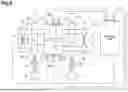
FIG. 6 is a schematic diagram for explaining deflection control of the roll press apparatus. The roll press apparatus 1 includes a control unit 80.
The control unit 80 is, for example, a PLC (Programmable Logic Controller). The PLC is a device having a processor, a memory, a display, an input/output unit, and the like. The control unit 80 may be configured as a computer system including, for example, a processor such as a CPU (Central Processing Unit), a memory such as a RAM (Random Access Memory) and a ROM (Read Only Memory), an input/output device such as a touch panel, a mouse, a keyboard, and a display, and a communication device such as a network card. Alternatively, the control unit 80 may be incorporated as a circuit. The control unit 80 may be realized by a plurality of control units (that is, may be physically divided).
The control unit 80 is connected to the sensor unit 60 and receives measurement values from the sensors. The control unit 80 calculates an amount of deflection based on the measurement values at the three locations. For example, a direction in which a detection point approaches a sensor is treated as positive. First, the control unit 80 calculates an average value by averaging two measurement values close to both ends of the upper roll 2 among the three measurement values. Then, the control unit 80 subtracts the average value from the measurement value at the center of the upper roll 2 to obtain the amount of deflection. The control unit 80 similarly calculates the amount of deflection for the lower roll 3. Then, the control unit 80 calculates an average value of the amount of deflection of the upper roll 2 and the amount of deflection of the lower roll 3.
The control unit 80, in response to detection of the deflection by the sensor unit 60, operates at least one of the first bending cylinder 51 and the second bending cylinder 52 such that a counter-deflection is applied to the upper roll 2 and the lower roll 3. The counter-deflection is a deflection that bends in a direction opposite to the deflection detected by the sensor unit 60. The control unit 80 determines an operation amount to cancel out the amount of deflection. The operation amount may be a fixed value. The control unit 80 outputs a signal indicating the determined operation amount to the first bending cylinder 51 and the second bending cylinder 52. As a result, the amounts of deflection of the upper roll 2 and the lower roll 3 change, and is detected again by the sensor unit 60. By repeating the above-described operation, the control unit 80 can reduce the deflections of the upper roll 2 and the lower roll 3.
[Details of Thickness Control]
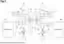
FIG. 7 is a schematic diagram for explaining thickness control of the roll press apparatus. The control unit 80 is connected to the thickness sensor unit 70 and receives measurement values from the sensors. The control unit 80 operates at least one of the first pressurizing cylinder 41 and the second pressurizing cylinder 42 such that a detection result of the thickness sensor unit 70 becomes a predetermined target value. When the thickness sensor unit 70 has two thickness sensor pairs (distance sensor pairs 71 and 72) corresponding to the first pressurizing cylinder 41 and the second pressurizing cylinder 42, the control unit 80 controls the first pressurizing cylinder 41 and the second pressurizing cylinder 42 independently. This allows for adjustment of the thickness and a thickness gradient in the width direction of the workpiece W. When the thickness sensor unit 70 has only one thickness sensor, the control unit 80 controls the first pressurizing cylinder 41 and the second pressurizing cylinder 42 in synchronization. This allows for adjustment of the thickness of the workpiece W.
The control unit 80 determines whether or not a difference from a target value is within an allowable range. When the difference from the target value is not within the allowable range, the control unit 80 determines an operation amount for the first pressurizing cylinder 41 and the second pressurizing cylinder 42. The operation amount may be a fixed value. The control unit 80 outputs a signal indicating the determined operation amount to the first pressurizing cylinder 41 and the second pressurizing cylinder 42. As a result, a distance between the upper roll 2 and the lower roll 3 changes, and is detected again by the thickness sensor unit 70. By repeating the above-described operation, the control unit 80 can perform feedback control of the thickness.
[Procedure for Measuring Deflection]
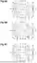
FIGS. 8A to 8C are schematic diagrams for explaining a procedure for measuring deflection of the roll press apparatus. As shown in FIG. 8A, first, the distance sensors are reset. The control unit 80, without conveying the workpiece W and in a state where no load is applied by any of the first pressurizing cylinder 41, the second pressurizing cylinder 42, the first bending cylinder 51, and the second bending cylinder 52, sets the measured distances of the first distance sensors 61, 62, and 63 and the second distance sensors 64, 65, and 66 to 0.
Subsequently, the control unit 80 operates each cylinder to a state in which a predetermined counter-deflection will be applied to the upper roll 2 and the lower roll 3 when the workpiece W is passed through. As a specific example, the control unit 80, without conveying the workpiece W and in a state where no load is applied by the first pressurizing cylinder 41 and the second pressurizing cylinder 42, operates the first bending cylinder 51 and the second bending cylinder 52. The predetermined counter-deflection is an amount of deflection applied in advance so as to cancel out the deflection that occurs when the workpiece W is subjected to the roll press process without deflection correction. The predetermined counter-deflection is obtained in advance, or is set based on experience or results from other apparatuses. For explaining the counter-deflection, FIG. 8B illustrates the shape of the rolls when the reaction force of the first bending cylinder 51 and the second bending cylinder 52 is received by applying a load to the first pressurizing cylinder 41 and the second pressurizing cylinder 42. In the actual procedure where no load is applied to the first pressurizing cylinder 41 and the second pressurizing cylinder 42, no counter-deflection occurs in the rolls at this stage.
Subsequently, as shown in FIG. 8C, the control unit 80 conveys the workpiece W and puts all of the first pressurizing cylinder 41, the second pressurizing cylinder 42, the first bending cylinder 51, and the second bending cylinder 52 into a state where a load can be applied. In this way, by setting the bending cylinders to a state in which they can apply a counter-deflection before conveying the workpiece W, the control unit 80 can suppress the occurrence of a large deflection at the start of the roll press process.
[Operation of Roll Press Apparatus]
FIG. 9 is a flowchart showing an operation for controlling deflection of the rolls. The flowchart (manufacturing method MT1) shown in FIG. 9 is started at a timing when an operation instruction is given by an operator, after the control unit 80 acquires an allowable range for the amount of deflection of the rolls. The allowable range for the amount of deflection of the rolls is, for example, stored in a storage device in advance. The allowable range for the amount of deflection of the rolls is acquired by the control unit 80 reading it from the storage device.
As shown in FIG. 9, as step S10, the sensor unit 60 detects the amount of deflection of the upper roll 2 and the lower roll 3. The control unit 80 acquires the amounts of deflection from the sensor unit 60. Subsequently, as step S12, the control unit 80 determines whether or not the amount of deflection detected in step S10 is within a pre-acquired allowable range.
When it is determined that the amount of deflection detected in step S10 is within the pre-acquired allowable range (step S12: YES), as step S14, the control unit 80 generates a command to hold the cylinder positions of the first bending cylinder 51 and the second bending cylinder 52. When it is determined that the amount of deflection detected in step S10 is not within the pre-acquired allowable range (step S12: NO), as step S16, the control unit 80 generates a command to extend or retract the first bending cylinder 51 and the second bending cylinder 52.
As step S18, the control unit 80 outputs the command generated in step S14 or step S16 to the first bending cylinder 51 and the second bending cylinder 52. The first bending cylinder 51 and the second bending cylinder 52 perform an operation based on the command. This concludes the flowchart shown in FIG. 9. The manufacturing method MT1 repeatedly executes the flowchart shown in FIG. 9 from the beginning until a termination condition is met. The termination condition is met when a scheduled process for the workpiece W is completed, or when a termination instruction is given by an operator.
FIG. 10 is a flowchart showing an operation for controlling a thickness of the workpiece. The flowchart (manufacturing method MT2) shown in FIG. 10 is started at a timing when an operation instruction is given by an operator, after the control unit 80 acquires a target value and an allowable range for the workpiece W.
As shown in FIG. 10, as step S20, the thickness sensor unit 70 detects the thickness of the workpiece W. The control unit 80 acquires the thickness of the workpiece W from the thickness sensor unit 70. Subsequently, as step S22, the control unit 80 determines whether or not the thickness of the workpiece W detected in step S20 is within a pre-acquired allowable range.
When it is determined that the thickness of the workpiece W detected in step S20 is within the pre-acquired allowable range (step S22: YES), as step S24, the control unit 80 generates a command to hold the cylinder positions of the first pressurizing cylinder 41 and the second pressurizing cylinder 42. When it is determined that the thickness of the workpiece W detected in step S20 is not within the pre-acquired allowable range (step S22: NO), as step S26, the control unit 80 generates a command to extend or retract the first pressurizing cylinder 41 and the second pressurizing cylinder 42.
As step S28, the control unit 80 outputs the command generated in step S24 or step S26 to the first pressurizing cylinder 41 and the second pressurizing cylinder 42. The first pressurizing cylinder 41 and the second pressurizing cylinder 42 perform an operation based on the command. This concludes the flowchart shown in FIG. 10. The manufacturing method MT2 repeatedly executes the flowchart shown in FIG. 10 from the beginning until a termination condition is met. The termination condition is met when a scheduled process for the workpiece W is completed, or when a termination instruction is given by an operator.
The flowcharts shown in FIGS. 9 and 10 can operate independently and may be executed simultaneously. When thickness sensors corresponding to the first pressurizing cylinder 41 and the second pressurizing cylinder 42, respectively, are provided, the flowchart shown in FIG. 10 may be executed for each of the first pressurizing cylinder 41 and the second pressurizing cylinder 42.
Summary of Embodiment
In the roll press apparatus 1, the shapes of the upper roll 2 and the lower roll 3 are measured to detect the deflection of the upper roll 2 and the lower roll 3, and in response to the detection of the deflection, at least one of the first bending cylinder 51 and the second bending cylinder 52 operates such that a counter-deflection is applied to the upper roll 2 and the lower roll 3. As a result, the deflection of the upper roll 2 and the lower roll 3 is canceled out, and an upper side and a lower side in a cross-section in the width direction of the workpiece W become straight lines without curvature. Therefore, the roll press apparatus 1 can obtain the workpiece W with reduced swelling or depression in the center in the width direction. Thus, compared to a case where the deflection of the upper roll 2 and the lower roll 3 is adjusted based on the thickness of the workpiece W after the roll press process, the roll press apparatus 1 can reduce the amount of generation of a workpiece having a non-uniform thickness in the width direction.
Note that, depending on the material of the workpiece W, conditions of the roll press process, and the like, merely adjusting the deflection of the upper roll 2 and the lower roll 3 may result in a shape where, although the upper and lower sides in the cross-section in the width direction of the workpiece W become straight, one of the both ends in the width direction of the workpiece W is thicker and the other is thinner. For this reason, the roll press apparatus 1 detects the thickness of the workpiece W pressed using the upper roll 2 and the lower roll 3 with the deflection canceled out, and adjusts the distance between the upper roll 2 and the lower roll 3 by feedback control. Since the upper and lower sides of the cross-section of the workpiece W are straight lines without curvature, it is not necessary to consider swelling or depression in the center in the width direction of the workpiece W. Therefore, it is not necessary to detect the thickness at three points in the width direction and determine their magnitudes. That is, since the roll press apparatus 1 can perform feedback by directly comparing the detected value of the thickness of the workpiece W after the roll press process with a target value to adjust the distance (gap) between the upper roll 2 and the lower roll 3, the feedback operation can be performed more quickly. Thus, the roll press apparatus 1 can reduce the amount (length) of non-conforming portions produced. In addition, since the number of thickness measurement locations can be one or two, equipment costs are also reduced.
[Modifications]
Although various exemplary embodiments have been described above, the present disclosure is not limited to the above-described exemplary embodiments, and various omissions, substitutions, and changes may be made.
For example, in the embodiment, the first pressurizing cylinder 41 and the second pressurizing cylinder 42 may be configured as a single pressurizing unit. Alternatively, the first pressurizing cylinder 41 and the second pressurizing cylinder 42 may operate in synchronization in the same manner.
The first main bearing 21 and the second main bearing 22 do not need to be fixedly supported by the main body frame 6. That is, a configuration in which the first main bearing 21 and the second main bearing 22 are pressurized by pressurizing cylinders may be adopted.
The roll press apparatus 1 may operate to apply a desired amount of deflection. For example, the roll press apparatus 1 can also adjust the thickness profile of the workpiece W after the roll press process to make the center in the width direction thicker or thinner.
When the workpiece W is intermittently coated (discontinuously coated), the roll press apparatus 1 may acquire a coating pattern before the roll press process. For example, one pattern detection sensor may be provided upstream of the upper roll 2 and the lower roll 3. The pattern detection sensor is, for example, a thickness sensor. Then, the roll press apparatus 1 may calculate a start timing and an end timing for pressing a coated portion based on the coating pattern. Then, the roll press apparatus 1 may adjust the first pressurizing cylinder 41 and the second pressurizing cylinder 42 so that an excessive load is not applied at the start timing and the end timing of pressing the coated portion. This can increase the yield rate.
The roll press apparatus 1 may include pattern detection sensors corresponding to the first pressurizing cylinder 41 and the second pressurizing cylinder 42. In this case, for each of the first pressurizing cylinder 41 and the second pressurizing cylinder 42, it is possible to adjust so that an excessive load is not applied at the start timing and the end timing of pressing the coated portion. In addition, even when there is a variation (undulation) in the coating thickness in a feeding direction, an appropriate roll press process can be performed, so that variations in the thickness of the workpiece W after the roll press process can be suppressed.
The roll press apparatus 1 may include three or more pattern detection sensors upstream of the upper roll 2 and the lower roll 3. In this case, the control unit 80 can determine a tendency (uniformity, inclination, etc.) of the thickness at the ends and the center in the width direction of the coating based on a detection result of the pattern detection sensors. The control unit 80 may correct an operation amount of the first bending cylinder 51 and the second bending cylinder 52 based on the determined tendency of the coating thickness. In addition, the control unit 80 calculates an increase or decrease in the distance (gap) between the upper roll 2 and the lower roll 3 that changes with this correction. Then, the control unit 80 may adjust the first pressurizing cylinder 41 and the second pressurizing cylinder 42 based on the calculated distance. Alternatively, the control unit 80 may apply the correction only to the upper rotation shaft 20 of the fixed roll (here, the upper roll 2). That is, when applying the correction, the control unit 80 may be configured to pull up only the first bending bearing 23 and the second bending bearing 24 upward. This simplifies control calculations for the first pressurizing cylinder 41 and the second pressurizing cylinder 42.
The roll press apparatus 1 may operate the first bending cylinder 51 and the second bending cylinder 52 by position control with position as a control value, or by load control with load as a control value.
Summary of Embodiments of the Present Disclosure
The Present Disclosure Includes the Following Aspects.
(Clause 1) A roll press apparatus comprises: a first roll having a first rotation shaft and a second roll having a second rotation shaft, configured to sandwich a workpiece being conveyed; a first bearing and a second bearing provided at respective ends of the first rotation shaft; a third bearing and a fourth bearing provided at respective ends of the second rotation shaft, the third bearing facing the first bearing, and the fourth bearing facing the second bearing; a first bending bearing and a second bending bearing provided at respective ends of the first rotation shaft, the first bending bearing being located outside of the first bearing, and the second bending bearing being located outside of the second bearing; a third bending bearing and a fourth bending bearing provided at respective ends of the second rotation shaft, the third bending bearing being located outside of the third bearing and facing the first bending bearing, and the fourth bending bearing being located outside of the fourth bearing and facing the second bending bearing; a first pressurizing unit configured to apply a load to at least one of the first bearing and the third bearing in a direction in which the first roll and the second roll move toward each other; a second pressurizing unit configured to apply a load to at least one of the second bearing and the fourth bearing in a direction in which the first roll and the second roll move toward each other; a first bending unit configured to apply a load to the first bending bearing and the third bending bearing in a direction in which the first roll and the second roll move toward or away from each other; a second bending unit configured to apply a load to the second bending bearing and the fourth bending bearing in a direction in which the first roll and the second roll move toward or away from each other; a sensor unit configured to measure shapes of the first roll and the second roll to detect deflection of the first roll and the second roll; and a control unit configured to, in response to detection of the deflection by the sensor unit, operate at least one of the first bending unit and the second bending unit such that a counter-deflection is applied to the first roll and the second roll.
In this roll press apparatus, the shapes of the first roll and the second roll are measured to detect the deflection of the first roll and the second roll, and in response to the detection of the deflection, at least one of the first bending unit and the second bending unit operates such that a counter-deflection is applied to the first roll and the second roll. The counter-deflection is a deflection that bends in a direction opposite to the deflection detected by the sensor unit. As a result, the deflection of the first roll and the second roll is canceled out, and an upper side and a lower side in a cross-section in the width direction of the workpiece become straight lines without curvature. Therefore, the roll press apparatus can obtain a workpiece with reduced swelling or depression in the center in the width direction. Thus, compared to a case where the deflection of the first roll and the second roll is adjusted based on the thickness of the workpiece after the roll press process, the roll press apparatus can reduce the amount of generation of a workpiece having a non-uniform thickness in the width direction.
(Clause 2) In the roll press apparatus according to clause 1, when the deflection detected by the sensor unit is a deflection in which a center of the first roll is moved away from the second roll more than both ends of the first roll are, and a deflection in which a center of the second roll is moved away from the first roll more than both ends of the second roll are, the control unit may perform at least one of: operating the first bending unit to apply a load to the first bending bearing and the third bending bearing in a direction in which the first roll and the second roll move away from each other; and operating the second bending unit to apply a load to the second bending bearing and the fourth bending bearing in a direction in which the first roll and the second roll move away from each other. For example, assuming that the first roll and the second roll are arranged vertically, the first roll has a shape that deflects such that its center protrudes upward more than its both ends, and the second roll has a shape that deflects such that its center protrudes downward more than its both ends. In this case, since a counter-deflection is applied to the first roll and the second roll by applying a load in a direction in which the opposing bending bearings move away from each other, the roll press apparatus can cancel out the deflection of the first roll and the second roll.
(Clause 3) In the roll press apparatus according to clause 1 or 2, when the deflection detected by the sensor unit is a deflection in which a center of the first roll is closer to the second roll than both ends of the first roll are, and a deflection in which a center of the second roll is closer to the first roll than both ends of the second roll are, the control unit may perform at least one of: operating the first bending unit to apply a load to the first bending bearing and the third bending bearing in a direction in which the first roll and the second roll move toward each other; and operating the second bending unit to apply a load to the second bending bearing and the fourth bending bearing in a direction in which the first roll and the second roll move toward each other. For example, assuming that the first roll and the second roll are arranged vertically, the first roll has a shape that deflects such that its center protrudes downward more than its both ends, and the second roll has a shape that deflects such that its center protrudes upward more than its both ends. In this case, since a counter-deflection is applied to the first roll and the second roll by applying a load in a direction in which the opposing bending bearings move toward each other, the roll press apparatus can cancel out the deflection of the first roll and the second roll.
(Clause 4) In the roll press apparatus according to any one of clauses 1 to 3, the sensor unit may comprise: three or more first distance sensors arranged in a straight line along the first rotation shaft; and three or more second distance sensors arranged in a straight line along the second rotation shaft. In this case, the roll press apparatus can detect the amount of deflection for each roll, and since the three distance sensors are arranged on the same straight line, the amount of deflection can be detected with high accuracy.
(Clause 5) In the roll press apparatus according to clause 4, each of the first distance sensors and each of the second distance sensors may be arranged on a straight line passing through a center point of a cross-section of the first roll and a center point of a cross-section of the second roll. In this case, the roll press apparatus can detect the deflection of the first roll and the second roll with higher accuracy.
(Clause 6) The roll press apparatus according to any one of clauses 1 to 5 may further comprise a thickness sensor unit provided downstream of the first roll and the second roll and configured to detect a thickness of the workpiece at one or two locations in a width direction of the workpiece, wherein the control unit may operate at least one of the first pressurizing unit and the second pressurizing unit such that a detection result of the thickness sensor unit becomes a predetermined target value. Depending on the material of the workpiece, conditions of the roll press process, and the like, merely adjusting the deflection of the upper and lower rolls may result in a shape where, although the upper and lower sides in the cross-section in the width direction of the workpiece become straight, one of the both ends in the width direction of the workpiece is thicker and the other is thinner. For this reason, the roll press apparatus detects the thickness of the workpiece pressed using the upper roll 2 and the lower roll 3 with the deflection canceled out, and adjusts the distance between the upper and lower rolls by feedback control. Since the upper and lower sides of the cross-section of the workpiece are straight lines without curvature, it is not necessary to consider swelling or depression in the center in the width direction of the workpiece. Therefore, it is not necessary to detect the thickness at three points in the width direction and determine their magnitudes. That is, since the roll press apparatus can perform feedback by directly comparing the detected value of the thickness of the workpiece after the roll press process with a target value to adjust the distance (gap) between the first roll and the second roll, the feedback operation can be performed more quickly. Thus, the roll press apparatus can reduce the amount (length) of non-conforming portions produced. In addition, since the number of thickness measurement locations can be one or two, equipment costs are also reduced.
(Clause 7) A method for manufacturing a processed product according to another aspect of the present disclosure is a method for manufacturing a processed product using a roll press apparatus, the roll press apparatus comprising: a first roll having a first rotation shaft and a second roll having a second rotation shaft, configured to sandwich a workpiece being conveyed; a first bearing and a second bearing provided at respective ends of the first rotation shaft; a third bearing and a fourth bearing provided at respective ends of the second rotation shaft, the third bearing facing the first bearing, and the fourth bearing facing the second bearing; a first bending bearing and a second bending bearing provided at respective ends of the first rotation shaft, the first bending bearing being located outside of the first bearing, and the second bending bearing being located outside of the second bearing; a third bending bearing and a fourth bending bearing provided at respective ends of the second rotation shaft, the third bending bearing being located outside of the third bearing and facing the first bending bearing, and the fourth bending bearing being located outside of the fourth bearing and facing the second bending bearing; a first pressurizing unit configured to apply a load to at least one of the first bearing and the third bearing in a direction in which the first roll and the second roll move toward each other; a second pressurizing unit configured to apply a load to at least one of the second bearing and the fourth bearing in a direction in which the first roll and the second roll move toward each other; a first bending unit configured to apply a load to the first bending bearing and the third bending bearing in a direction in which the first roll and the second roll move toward or away from each other; a second bending unit configured to apply a load to the second bending bearing and the fourth bending bearing in a direction in which the first roll and the second roll move toward or away from each other; and a sensor unit configured to measure shapes of the first roll and the second roll to detect deflection of the first roll and the second roll, the method comprising: determining whether or not the deflection has been detected by the sensor unit; and operating at least one of the first bending unit and the second bending unit such that a counter-deflection is applied to the first roll and the second roll in response to detection of the deflection by the sensor unit. This method provides the same effects as the apparatus described above.
Claims
What is claimed is:1. A roll press apparatus comprising:
a first roll having a first rotation shaft and a second roll having a second rotation shaft, configured to sandwich a workpiece being conveyed;
a first bearing and a second bearing provided at respective ends of the first rotation shaft;
a third bearing and a fourth bearing provided at respective ends of the second rotation shaft, the third bearing facing the first bearing, and the fourth bearing facing the second bearing;
a first bending bearing and a second bending bearing provided at respective ends of the first rotation shaft, the first bending bearing being located outside of the first bearing, and the second bending bearing being located outside of the second bearing;
a third bending bearing and a fourth bending bearing provided at respective ends of the second rotation shaft, the third bending bearing being located outside of the third bearing and facing the first bending bearing, and the fourth bending bearing being located outside of the fourth bearing and facing the second bending bearing;
a first pressurizing unit configured to apply a load to at least one of the first bearing and the third bearing in a direction in which the first roll and the second roll move toward each other;
a second pressurizing unit configured to apply a load to at least one of the second bearing and the fourth bearing in a direction in which the first roll and the second roll move toward each other;
a first bending unit configured to apply a load to the first bending bearing and the third bending bearing in a direction in which the first roll and the second roll move toward or away from each other;
a second bending unit configured to apply a load to the second bending bearing and the fourth bending bearing in a direction in which the first roll and the second roll move toward or away from each other;
a sensor unit configured to measure shapes of the first roll and the second roll to detect deflection of the first roll and the second roll; and
a control unit configured to, in response to detection of the deflection by the sensor unit, operate at least one of the first bending unit and the second bending unit such that a counter-deflection is applied to the first roll and the second roll.
2. The roll press apparatus according to claim 1, wherein when the deflection detected by the sensor unit is a deflection in which a center of the first roll is moved away from the second roll more than both ends of the first roll are, and a deflection in which a center of the second roll is moved away from the first roll more than both ends of the second roll are,
the control unit is configured to perform at least one of:
operating the first bending unit to apply a load to the first bending bearing and the third bending bearing in a direction in which the first roll and the second roll move away from each other; and
operating the second bending unit to apply a load to the second bending bearing and the fourth bending bearing in a direction in which the first roll and the second roll move away from each other.
3. The roll press apparatus according to claim 1, wherein when the deflection detected by the sensor unit is a deflection in which a center of the first roll is closer to the second roll than both ends of the first roll are, and a deflection in which a center of the second roll is closer to the first roll than both ends of the second roll are,
the control unit is configured to perform at least one of:
operating the first bending unit to apply a load to the first bending bearing and the third bending bearing in a direction in which the first roll and the second roll move toward each other; and
operating the second bending unit to apply a load to the second bending bearing and the fourth bending bearing in a direction in which the first roll and the second roll move toward each other.
4. The roll press apparatus according to claim 1, wherein the sensor unit comprises:
three or more first distance sensors arranged in a straight line along the first rotation shaft; and
three or more second distance sensors arranged in a straight line along the second rotation shaft.
5. The roll press apparatus according to claim 4, wherein each of the first distance sensors and each of the second distance sensors are arranged on a straight line passing through a center point of a cross-section of the first roll and a center point of a cross-section of the second roll.
6. The roll press apparatus according to claim 1, further comprising a thickness sensor unit provided downstream of the first roll and the second roll and configured to detect a thickness of the workpiece at one or two locations in a width direction of the workpiece,
wherein the control unit is configured to operate at least one of the first pressurizing unit and the second pressurizing unit such that a detection result of the thickness sensor unit becomes a predetermined target value.
7. A method for manufacturing a processed product using a roll press apparatus, the roll press apparatus comprising:
a first roll having a first rotation shaft and a second roll having a second rotation shaft, configured to sandwich a workpiece being conveyed;
a first bearing and a second bearing provided at respective ends of the first rotation shaft;
a third bearing and a fourth bearing provided at respective ends of the second rotation shaft, the third bearing facing the first bearing, and the fourth bearing facing the second bearing;
a first bending bearing and a second bending bearing provided at respective ends of the first rotation shaft, the first bending bearing being located outside of the first bearing, and the second bending bearing being located outside of the second bearing;
a third bending bearing and a fourth bending bearing provided at respective ends of the second rotation shaft, the third bending bearing being located outside of the third bearing and facing the first bending bearing, and the fourth bending bearing being located outside of the fourth bearing and facing the second bending bearing;
a first pressurizing unit configured to apply a load to at least one of the first bearing and the third bearing in a direction in which the first roll and the second roll move toward each other;
a second pressurizing unit configured to apply a load to at least one of the second bearing and the fourth bearing in a direction in which the first roll and the second roll move toward each other;
a first bending unit configured to apply a load to the first bending bearing and the third bending bearing in a direction in which the first roll and the second roll move toward or away from each other;
a second bending unit configured to apply a load to the second bending bearing and the fourth bending bearing in a direction in which the first roll and the second roll move toward or away from each other; and
a sensor unit configured to measure shapes of the first roll and the second roll to detect deflection of the first roll and the second roll,
the method comprising:
determining whether or not the deflection has been detected by the sensor unit; and
operating at least one of the first bending unit and the second bending unit such that a counter-deflection is applied to the first roll and the second roll in response to detection of the deflection by the sensor unit.
Images & Drawings included:


Sources:
- United States Patent and Trademark Office - verify current appl. status at the USPTO↗
Recent applications in this class:
- » 20250312834 2025-10-09
ROLLING APPARATUS - » 20240408659 2024-12-12
ROLLING MILL AND ROLLING METHOD - » 20240216970 2024-07-04
METHOD FOR PRODUCING A ROLLED PRODUCT WITH A BOX PROFILE - » 20240091834 2024-03-21
HAIRPIN COIL FLATTENING CONTROL SYSTEM AND METHOD THEREFOR - » 20220347730 2022-11-03
Flatness-measuring apparatus for measuring the flatness of a metal strip - » 20210268561 2021-09-02
Decoupled adjustment of contour and flatness of a metal strip - » 20210260634 2021-08-26
Strip flatness prediction method considering lateral spread during rolling - » 20210178443 2021-06-17
Targeted adjusting of the contour using corresponding specifications - » 20200338609 2020-10-29
METHOD FOR CHANNEL DECOUPLING OF WHOLE-ROLLER FLATNESS METER FOR COLD-ROLLED STRIP - » 20190022724 2019-01-24
Systems and methods for controlling flatness of a metal substrate with low pressure rolling
Recent applications for this Assignee:
- » 20260063463 2026-03-05
WEIGHT MEASUREMENT SYSTEM, INFORMATION PROCESSING DEVICE, AND WEIGHT MEASUREMENT METHOD - » 20260061624 2026-03-05
CONTROL DEVICE, CONTROL METHOD, STORAGE MEDIUM, AND HANDLING SYSTEM - » 20260061377 2026-03-05
MIXER - » 20260036477 2026-02-05
TORQUE SENSOR - » 20260033689 2026-02-05
POWDER FEED DEVICE - » 20250375850 2025-12-11
GRINDER AND ROBOT - » 20250375847 2025-12-11
GRINDER - » 20250375835 2025-12-11
LASER MARKING APPARATUS AND LASER MARKING METHOD - » 20250369813 2025-12-04
TACTILE SENSOR - » 20250367817 2025-12-04
ROBOT TOOL