LIQUID SUPPLY DEVICE
US20260070189A1
2026-03-12
19/289,866
2025-08-04
Smart Summary: A device is designed to spray liquid onto a workpiece or jig. It has a part that holds the liquid and a pump that moves the liquid from this part. The liquid is then sent through pipes to a spray section that releases it onto the workpiece. One pipe carries the liquid from the pump, while another pipe sprays it out. This setup allows for controlled spraying of the liquid in specific amounts. 🚀 TL;DR
Abstract:
A liquid supply device for spraying liquid onto a workpiece or a jig for the workpiece. The liquid supply device includes an accommodation portion configured to accommodate the liquid, a pump configured to pump the liquid from the accommodation portion, a spray portion configured to suction the liquid pumped from the accommodation portion to spray the liquid onto the workpiece, a pump-side supply pipe connected to the accommodation portion, the pump-side supply pipe being configured to discharge, by a predetermined amount at a time, the liquid pumped by the pump, and a spray-side supply pipe including an upstream end portion into which the liquid discharged from the pump-side supply pipe flows and that is open to an atmosphere, and a downstream end portion configured to spray the liquid flowing from the upstream end portion via the spray portion.
Assignee:
- JTEKT MACHINE SYSTEMS CORPORATION 3 🇯🇵 Osaka, Japan
Applicant:
Interested in similar patents?
Get notified when new applications in this technology area are published.
Classification:
B24B57/02 » CPC main
Devices for feeding, applying, grading or recovering grinding, polishing or lapping agents for feeding of fluid, sprayed, pulverised, or liquefied grinding, polishing or lapping agents
Description
CROSS-REFERENCE TO RELATED APPLICATIONS
This application is based on and claims priority under 35 USC 119 from Japanese Patent Application No. 2024-158386 filed on Sep. 12, 2024, the entire content of which is incorporated herein by reference.
TECHNICAL FIELD
The present disclosure relates to a liquid supply device.
BACKGROUND ART
JP2004-207422A discloses a polishing device including a tube-type pump as an example of a liquid supply device. This tube-type pump supplies slurry to a CMP device via a vinyl chloride type tube.
JPH11-176796A discloses a device showing another example of the liquid supply device. This device includes a carrier pipe that suctions an atomized IPA solution and a nozzle that discharges a mixed fluid in which the IPA solution and a carrier gas are mixed.
JP5311938B discloses a substrate processing device including still another example of the liquid supply device. The substrate processing device includes a mixed mist liquid supply portion, a mist liquid supply pipe, and an ejecting portion including a jetting nozzle.
JP5311938B, the mixed mist liquid supply portion accommodates a mixed mist liquid obtained by mixing pure water or a cleaning liquid with an abrasive. The mist liquid supply pipe has one end connected to the mixed mist liquid supply portion and the other end surrounded by the jetting nozzle. The ejecting portion ejects the mixed mist liquid supplied from the mist liquid supply pipe toward the front of the jetting nozzle.
As described in JP2004-207422A, JPH11-176796A, and JP5311938B, various supply methods have been known in the related art for supplying liquid.
For example, it is conceivable to adopt a configuration such as that disclosed in JP2004-207422A, and to drop liquid such as slurry from a tip of a tube. In this case, although an amount of the supplied liquid can be kept substantially constant, the liquid can only be supplied to one point on the workpiece, and there is room for improvement in ease of use.
On the other hand, it is conceivable to adopt a configuration such as that disclosed in JPH11-176796A or JP5311938B, and to spray liquid supplied from an accommodation portion such as the mixed mist liquid supply portion onto the workpiece. In this case, although the liquid can be supplied over a wide area on the workpiece, it is not easy to keep the amount of the supplied liquid substantially constant, and there is room for improvement in ease of use.
In addition, when a configuration such as that disclosed in JPH11-176796A or JP5311938B is adopted, depending on a positional relationship between a spray portion, such as the jetting nozzle, and the accommodation portion, there is a possibility that the liquid may flow back from the jetting nozzle to the accommodation portion, or the liquid may leak from a spray port due to a siphonic phenomenon.
SUMMARY OF INVENTION
Aspect of non-limiting embodiments of the present disclosure relates to keep an amount of liquid sprayed onto a workpiece constant without causing backflow and leakage of the liquid.
Aspects of certain non-limiting embodiments of the present disclosure address the features discussed above and/or other features not described above. However, aspects of the non-limiting embodiments are not required to address the above features, and aspects of the non-limiting embodiments of the present disclosure may not address features described above.
According to an aspect of the present disclosure, there is provided a liquid supply device for spraying liquid onto a workpiece or a jig for the workpiece, the liquid supply device including:
-
- an accommodation portion configured to accommodate the liquid;
- a pump configured to pump the liquid from the accommodation portion;
- a spray portion configured to suction the liquid pumped from the accommodation portion to spray the liquid onto the workpiece;
- a pump-side supply pipe connected to the accommodation portion, the pump-side supply pipe being configured to discharge, by a predetermined amount at a time, the liquid pumped by the pump; and
- a spray-side supply pipe including
- an upstream end portion into which the liquid discharged from the pump-side supply pipe flows and that is open to an atmosphere; and
- a downstream end portion configured to spray the liquid flowing from the upstream end portion via the spray portion.
BRIEF DESCRIPTION OF DRAWINGS
Exemplary embodiment(s) of the present invention will be described in detail based on the following figures, wherein:
FIG. 1 is a schematic diagram illustrating a liquid supply device;
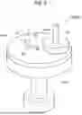
FIG. 2 is a perspective view illustrating a processing device for a workpiece and a spray portion of the liquid supply device;
FIG. 3 is a cross-sectional view illustrating an upstream end portion of a spray-side supply pipe;
FIG. 4 is a block diagram illustrating a controller of the liquid supply device;
FIG. 5 is a diagram corresponding to FIG. 1 and showing a modification of the liquid supply device; and
FIG. 6 is a view corresponding to FIG. 2 and showing a modification of the processing device.
DESCRIPTION OF EMBODIMENTS
Hereinafter, embodiments of the present disclosure will be described with reference to the drawings. The following description is illustrative.
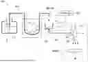
FIG. 1 is a schematic diagram illustrating a liquid supply device 1. FIG. 2 is a perspective view illustrating a processing device 200 for a workpiece W and a spray portion 4 of the liquid supply device 1. FIG. 3 is a cross-sectional view illustrating an upstream end portion 71 of a spray-side supply pipe 7. FIG. 4 is a block diagram illustrating a controller 100 of the liquid supply device 1.
Overall Configuration
The liquid supply device 1 illustrated in FIG. 1 is configured to spray liquid Lq to the workpiece W or a jig for the workpiece W. The workpiece W is ground or polished by the processing device 200 illustrated in FIG. 2.
The liquid supply device 1 may be regarded as a device independent of the processing device 200 or may be regarded as a part of the processing device 200. The following description corresponds to the former case. That is, in the present embodiment, the liquid supply device 1 and the processing device 200 constitute a processing system S illustrated in FIG. 1. On the other hand, in the latter case, the term “liquid supply device 1” may be appropriately replaced with the term “processing device 200”.
Here, the workpiece W according to the present embodiment is a thin plate-shaped workpiece W.
The liquid Lq sprayed onto the workpiece W can be appropriately selected according to a type of processing performed by the processing device 200, a use of the liquid Lq, and the like. The liquid Lq may be pure water, slurry obtained by dissolving abrasive grains in a solution, or chemical products such as hydrochloric acid and sulfuric acid.
In addition, a fluid obtained by mixing liquid and another mixture, such as the slurry, may be used as the liquid Lq sprayed onto the workpiece W. Such a mixture contains, in addition to the abrasive grains described above, a polishing material. The polishing material includes one or more of SiC, SiO2, Al2O3, CeO2, Mn2O3, and a diamond.
Processing Device 200
As illustrated in FIG. 2, the processing device 200 is formed as a surface grinding device (for example, a vertical surface grinding machine) that grinds one surface (upper surface) of a thin circular workpiece W with a grindstone 201. The processing device 200 as the grinding device includes a spindle 202 and a chuck 203 in addition to the grindstone 201. The spindle 202 is vertically movable and rotates about a central axis extending in a vertical direction. The grindstone 201 is attached to a lower end of the spindle 202 and rotates together with the spindle 202. The chuck 203 holds the circular workpiece W on an upper surface of the chuck 203. The chuck 203 is an example of the “jig for the workpiece W” in the present embodiment.
The chuck 203 according to the present embodiment is, for example, a vacuum chuck made of a porous body or SUS and having an opened intake hole. The term “jig for the workpiece W” as used herein also includes a jig configured to hold and position the workpiece W.
The processing device 200 grinds the upper surface of the workpiece W by causing the rotating grindstone 201 to cut downward into the upper surface of the workpiece W held by the chuck 203. During the grinding, the liquid Lq as a processing liquid is supplied onto the workpiece W or the surface of the grindstone 201 by the liquid supply device 1. An operation of the processing device 200 is controlled by a control signal input from the same controller 100 as that of the liquid supply device 1. Different controllers 100 may be used in the processing device 200 and the liquid supply device 1.
Liquid Supply Device 1
Referring back to FIG. 1, the details of the liquid supply device 1 will be described below. Terms “upstream” and “downstream” in the following description respectively correspond to “upstream” and “downstream” in a flow direction of the liquid Lq.
As illustrated in FIG. 1, the liquid supply device 1 includes an accommodation portion 2, a pump 3, the spray portion 4, a supply pipe 5, and the controller 100.
The accommodation portion 2 is configured to accommodate the liquid Lq. The accommodation portion 2 according to the present embodiment includes a container configured to store the liquid Lq such as slurry, for example. The accommodation portion 2 is connected to the spray portion 4 via the supply pipe 5.
Although details will be described later, the supply pipe 5 includes an upstream pump-side supply pipe 6 connected to the accommodation portion 2, and the downstream spray-side supply pipe 7 connected to the spray portion 4. Among these, at least the pump-side supply pipe 6 is made of an elastic tubular member such as a resin hose.
The pump 3 is configured to pump the liquid Lq from the accommodation portion 2. The pump 3 is configured to operate upon receiving the control signal from the controller 100. In a case where the pump 3 is operated, the liquid Lq is suctioned out from the accommodation portion 2 and pumped.
Specifically, the pump 3 is disposed in the middle of the pump-side supply pipe 6 having elasticity. More specifically, the pump 3 according to the present embodiment is a roller pump. The pump 3 is configured to control a flow of the liquid Lq through the pump-side supply pipe 6 by squeezing the pump-side supply pipe 6 having elasticity. It is not essential that the pump 3 be constituted by the roller pump.
The spray portion 4 is configured to suction the liquid Lq pumped from the accommodation portion 2 to spray the liquid Lq onto the workpiece W. Specifically, the spray portion 4 is configured to spray the liquid Lq, as the processing liquid, onto a surface of the workpiece W to be ground or polished. The spray portion 4 according to the present embodiment includes, for example, a vacuum ejector.
Specifically, the spray portion 4 according to the present embodiment includes a first supply port 41 to which compressed air is supplied, a second supply port 42 from which the liquid Lq is suctioned out, and a spray port 43. In a case where the compressed air is supplied to the first supply port 41, a negative pressure (vacuum) is generated by a venturi effect. By suctioning the liquid Lq from the second supply port 42 by the negative pressure, the spray portion 4 can discharge the suctioned liquid Lq in a mist form from the spray port 43.
It is not essential that the spray portion 4 be constituted by the vacuum ejector. Any configuration can be used for the spray portion 4, such as a general binary fluid nozzle, as long as the negative pressure is generated in the spray portion 4 and the liquid Lq is discharged in the mist form by the negative pressure.
The supply pipe 5 fluidly connects the accommodation portion 2 and the spray portion 4. The supply pipe 5 includes a tubular member such as a hose configured to circulate the liquid Lq.
Further, the supply pipe 5 according to the present embodiment includes the pump-side supply pipe 6 connected to the accommodation portion 2 and forming an upstream flow path, and the spray-side supply pipe 7 connected to the spray portion 4 and forming a downstream flow path. The pump-side supply pipe 6 and the spray-side supply pipe 7 are constituted by separate tubular members.
The pump-side supply pipe 6 includes an upstream end portion 61 connected to the accommodation portion 2, and a downstream end portion 62 configured to discharge the liquid Lq toward the spray-side supply pipe 7. As described above, the pump-side supply pipe 6 is formed of an elastic tubular member such as a resin hose. The pump 3 is disposed on the way from the upstream end portion 61 to the downstream end portion 62 of the pump-side supply pipe 6.
The upstream end portion 61 of the pump-side supply pipe 6 is configured to cause the liquid Lq to flow in from the accommodation portion 2. The upstream end portion 61 is inserted into the accommodation portion 2 and suctions the liquid Lq from the accommodation portion 2 as the pump 3 operates.
The downstream end portion 62 of the pump-side supply pipe 6 is configured to discharge the liquid pumped by the operation of the pump, by a predetermined amount at a time. As shown in FIG. 3, the downstream end portion 62 includes a discharge port 62a configured to drop the liquid Lq, by a predetermined amount at a time.
The spray-side supply pipe 7 includes an upstream end portion 71 into which the liquid Lq discharged from the pump-side supply pipe 6 flows, and a downstream end portion 72 connected to the spray portion 4.
As shown in FIG. 3, the upstream end portion 71 of the spray-side supply pipe 7 is open to the atmosphere. A container 73 is connected to the upstream end portion 71. The container 73 is configured to temporarily accommodate the liquid Lq dropped from the discharge port 62a.
Specifically, the container 73 includes a top portion 73a that opens toward the discharge port 62a of the pump-side supply pipe 6, and a bottom portion 73b at which the upstream end portion 71 of the spray-side supply pipe 7 opens. The liquid Lq dropped from the discharge port 62a can be received via an opening of the top portion 73a.
The container 73 has a mortar shape in which the bottom portion 73b is reduced in diameter with respect to the top portion 73a. With the mortar shape, the liquid Lq flowing in from the opening of the top portion 73a can be smoothly guided to an opening of the bottom portion 73b.
An optical sensor 8 configured to optically detect a droplet Dq of the liquid Lq dropped into the container 73 is disposed on the container 73. The optical sensor 8 is used for monitoring a droplet formed of the liquid Lq.
Specifically, the optical sensor 8 includes a light projecting portion 81 configured to project light in a direction O2 intersecting a dropping direction O1 of the liquid Lq and a light receiving portion 82 configured to receive the light projected from the light projecting portion 81.
The optical sensor 8 is electrically connected to the controller 100. The optical sensor 8 is configured to input a detection signal thereof to the controller 100. The controller 100 is configured to determine a dropping status of the liquid Lq, based on an electric signal received from the optical sensor 8.
For example, when the liquid Lq is being dropped normally, the light projected from the light projecting portion 81 is periodically blocked by the droplet Dq. On the other hand, when the liquid Lq is not being dropped normally, the light projected from the light projecting portion 81 will be non-periodically blocked or not blocked by the droplet Dq.
Therefore, the light receiving portion 82 inputs, to the controller 100, the electric signal (detection signal) indicating luminance or the like of the received light. The controller 100 can determine the dropping status of the liquid Lq based on signal strength, reception interval, and the like of the electrical signal thus input.
As shown in FIG. 3, the discharge port 62a of the pump-side supply pipe 6 and the top portion 73a of the container 73 face each other with a gap therebetween in the dropping direction O1 of the liquid Lq. Thus, a dropping time of the droplet Dq can be ensured, which is advantageous for the detection of the optical sensor 8.
Operation of Liquid Supply Device 1
When the liquid supply device 1 is used, the controller 100 operates the pump 3. Accordingly, the pump 3 squeezes the pump-side supply pipe 6, thereby suctioning the liquid Lq out of the accommodation portion 2. Further, before or after the operation of the pump 3, the controller 100 starts to process the workpiece W by the processing device 200.
Subsequently, as illustrated in FIG. 3, the liquid Lq suctioned out from the accommodation portion 2 is dropped from the discharge port 62a located at the downstream end portion 62 of the pump-side supply pipe 6. The number of droplets Dq at that time is monitored by the optical sensor 8. As shown in the same figure, the liquid Lq dropped from the pump-side supply pipe 6 is collected by the container 73 connected to the upstream end portion 71 of the spray-side supply pipe 7, and flows through the spray-side supply pipe 7.
When the processing device 200 starts to process, the controller 200 starts to supply the compressed air to the first supply port 41 of the spray portion 4. High-pressure air supplied from the first supply port 41 generates the negative pressure in the spray portion 4. The spray portion 4 suctions the liquid Lq from the downstream end portion 72 of the spray-side supply pipe 7 by the negative pressure. During the processing of the processing device 200, the compressed air is always supplied to the spray portion 4. Accordingly, the spray portion 4 always operates and continues to suction the liquid Lq from the container 73.
Thereafter, the spray portion 4 sprays the liquid Lq suctioned from the spray-side supply pipe 7 from the spray port 43. Accordingly, the liquid Lq is supplied to the workpiece W or the jig (for example, the chuck 203).
Significance or the like of Liquid Supply Device 1
As described above, the supply pipe 5 connecting the accommodation portion 2 and the spray portion 4 is divided into the pump-side supply pipe 6 and the spray-side supply pipe 7 (see FIG. 1). As shown in FIG. 3, the upstream end portion 71 of the spray-side supply pipe 7 located at a dividing portion Pd is open to the atmosphere.
If the pump-side supply pipe 6 and the spray-side supply pipe 7 are formed by one pipe line without being divided, there is a possibility that more liquid Lq than necessary is suctioned from the accommodation portion 2 via the one pipe line depending on a suction force of the spray portion 4. This is inconvenient in terms of keeping an amount of liquid Lq supplied to the workpiece W constant.
On the other hand, since the upstream end portion 71 of the spray-side supply pipe 7 is open to the atmosphere, the spray portion 4 can suction only the liquid Lq discharged from the pump-side supply pipe 6 and flowing into the spray-side supply pipe 7 and use the liquid Lq for spraying. Even if the suction force of the spray portion 4 becomes excessive, a situation in which the more liquid Lq than necessary is suctioned can be avoided. Therefore, the amount of the liquid Lq sprayed onto the workpiece W becomes constant.
Further, as illustrated in FIGS. 1 and 3, the supply pipe 5 is divided into the pump-side supply pipe 6 and the spray-side supply pipe 7, and the dividing portion Pd is opened to the atmosphere, so that it is possible to prevent backflow of the liquid Lq from the spray portion 4 to the accommodation portion 2 and to prevent a leakage of the liquid Lq from the spray port 43 which is caused by a siphonic phenomenon.
Further, in the case of using the configuration according to the above-described embodiment, the negative pressure always acts on the spray-side supply pipe 7 by the suction force exerted by the spray portion 4. Therefore, even if a pipe line length from the accommodation portion 2 to the spray portion 4 (pipe line length of the entire supply pipe 5) is long, the liquid Lq flowing into the upstream end portion 71 of the spray-side supply pipe 7 can be guided to the spray portion 4 without a delay. This makes it possible to spray the liquid Lq quickly.
Since the supply pipe 5 is divided into the pump-side supply pipe 6 and the spray-side supply pipe 7, the pump-side supply pipe 6 and the spray-side supply pipe 7 can be individually replaced. Accordingly, for example, since it becomes possible to independently replace the pump-side supply pipe 6, which is subject to a risk of damage or deterioration due to operation of the pump 3, maintainability of liquid Lq supply device can be improved.
Further, as described above, even if the spray-side supply pipe 7 is lengthened, there is no delay in the supply of the liquid Lq to the spray portion 4, so even if the pipe line length from the accommodation portion 2 to the spray portion 4 (total pipe line length of the pump-side supply pipe 6 and the spray-side supply pipe 7) is long, a pipe line length occupied by the pump-side supply pipe 6 can be shortened. Accordingly, the pump-side supply pipe 6 can be easily replaced, and thus the maintainability of the liquid supply device 1 can be further improved.
Such a configuration is particularly effective in a case in which the pump 3 as the roller pump is configured to squeeze the pump-side supply pipe 6 having elasticity.
As illustrated in FIG. 3, since the liquid Lq is dropped from the discharge port 62a, a discharge amount of the liquid Lq from the pump-side supply pipe 6 to the spray-side supply pipe 7 can be kept constant. Further, it is possible to easily control the discharge amount of liquid Lq based on the number of droplets Dq discharged per unit time and the like.
When the liquid is to be detected by a general flow rate sensor, a difference may occur between a detection value of the flow rate sensor and an amount of the liquid Lq actually dropped from the discharge port 62a depending on states of the pump 3 and the pump-side supply pipe 6. This is inconvenient in terms of keeping the amount of the liquid Lq sprayed onto the workpiece W constant.
On the other hand, as illustrated in FIG. 3, in the present embodiment, the optical sensor 8 optically detects the liquid Lq dropped from the discharge port 62a. With this configuration, the amount of the liquid Lq dropped from the discharge port 62a can be directly detected, which is advantageous in keeping the amount of the liquid sprayed onto the workpiece W constant.
Modification of Liquid Supply Device 1
In the above embodiment, as illustrated in FIG. 1, the configuration focusing on one accommodation portion 2 and the supply of one liquid Lq accommodated therein is shown as an example, but the present disclosure is not limited to such a configuration. The present disclosure may also be applied to devices configured to supply two or more liquids Lq.
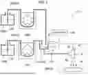
FIG. 5 is a diagram corresponding to FIG. 1 and showing a modification of the liquid supply device 1. Hereinafter, the liquid Lq illustrated in FIGS. 1 to 4 is referred to as a first liquid Lq1, the accommodation portion 2 is referred to as a first accommodation portion 1002, the pump-side supply pipe 6 is referred to as a first pump-side supply pipe 1006, and the pump 3 is referred to as a first pump 1003.
A liquid supply device 1′ according to the modification includes the first accommodation portion 1002 that accommodates the first liquid Lq1, the first pump 1003, the spray portion 4, the first pump-side supply pipe 1006, the spray-side supply pipe 7, the optical sensor 8, and the controller 100. Configurations of these elements are the same as those illustrated in FIGS. 1 to 4 except for the names of some elements.
The liquid supply device 1′ according to the modification includes a second accommodation portion 2002, a second pump 2003, and a second pump-side supply pipe 2006 in addition to the above-described elements. Configurations of these elements are substantially the same as the configurations of the first accommodation portion 1002, the first pump 1003, and the first pump-side supply pipe 1006 except that these elements are elements related to accommodation and circulation of the first liquid Lq1 or elements related to accommodation and circulation of a second liquid Lq2 indicating liquid other than the first liquid Lq1.
That is, the second accommodation portion 2002 accommodates the second liquid Lq2. The second pump 2003 operates to pump the second liquid Lq2 from the second accommodation portion 2002. The second pump-side supply pipe 2006 is connected to the second accommodation portion 2002 and discharges the second liquid Lq2 pumped by the second pump 2003 by a predetermined amount at a time.
Further, the spray portion 4 and the spray-side supply pipe 7 are shared by the first liquid Lq1 and the second liquid Lq2. That is, in the liquid supply device 1′ according to the modification, the first liquid Lq1 discharged from the first pump-side supply pipe 1006 and the second liquid Lq2 discharged from the second pump-side supply pipe 2006 flow into the upstream end portion 71 of the spray-side supply pipe 7.
The controller 100 may alternatively operate the first pump 1003 and the second pump 2003. In this case, the liquid Lq sprayed onto the workpiece W can be switched to the first liquid Lq1 or the second liquid Lq2. The liquid Lq can be used differently.
Instead of the operation, the controller 100 may simultaneously operate the first pump 1003 and the second pump 2003. In this case, the liquid Lq sprayed onto the workpiece W can be a mixed liquid of the first liquid Lq1 and the second liquid Lq2.
As described above, it is sufficient that a suction force (negative pressure) exerted on the supply pipe 5 by the spray portion 4 is exerted only on the spray-side supply pipe 7. This is suitable for spraying, in each time the liquid Lq flows into the spray-side supply pipe 7 from the first pump-side supply pipe 1006 or the second pump-side supply pipe 2006, all the liquid Lq that has flowed, and as a result, this is convenient for preventing the remaining of the liquid Lq in the spray-side supply pipe 7.
Therefore, even when the spray-side supply pipe 7 is shared by the first liquid Lq1 and the second liquid Lq2 as in the liquid supply device 1′ according to the modification, unintended mixing of the first liquid Lq1 and the second liquid Lq2 in the spray-side supply pipe 7 can be prevented. Thus, it is possible to accurately distinguish between the first liquid Lq1 and the second liquid Lq2 and to accurately adjust a mixing ratio when the mixed liquid of the first liquid Lq1 and the second liquid Lq2 is supplied.
In addition to the first liquid Lq1 and the second liquid Lq2, an accommodation portion, a pump, and a pump-side supply pipe, which are related to a third liquid, may be provided. Similar to the liquid supply device 1′ according to the modification, various processes can be accurately performed by sharing the spray-side supply pipe 7. Four or more kinds of liquids such as a fourth liquid may be used.
Modification of Processing Device 200
In the above-described embodiment, as illustrated in FIG. 2, the processing device 200 configured as the surface grinding device is illustrated, but the present disclosure is not limited to such a configuration. The present disclosure can also be applied to a processing device configured to polish the workpiece W.
FIG. 6 is a view corresponding to FIG. 2 and showing a modification of the processing device 200. As shown in FIG. 6, a processing device 1200 according to the modification is configured as a polishing device that polishes one surface (lower surface) of the thin circular workpiece W with a polishing pad 1201. The processing device 1200 as the polishing device may be, for example, a CMP device.
As shown in FIG. 6, the processing device 1200 as the polishing device includes a surface plate 1202 and a polishing head 1203 in addition to the polishing pad 1201.
The surface plate 1202 rotates around a central axis extending in a vertical direction. The polishing pad 1201 is attached to an upper end of the surface plate 1202 and rotates together with the surface plate 1202. The polishing head 1203 rotates about a central axis extending in the vertical direction. The polishing head 1203 holds the circular workpiece W on a lower surface of the polishing head 1203. The polishing head 1203 presses the workpiece W against the polishing pad 1201.
The processing device 1200 polishes a lower surface of the workpiece W by pressing the lower surface of the workpiece W held by the polishing head 1203 against an upper surface of the rotating polishing pad 1201. During the polishing, the liquid Lq as a processing liquid is supplied onto a surface of the workpiece W or the polishing pad 1201 by the liquid supply device 1. An operation of the processing device 1200 is controlled by a control signal input from the same controller 100 as that of the liquid supply device 1. Different controllers 100 may be used in the processing device 1200 and the liquid supply device 1.
The liquid supply device 1 or the modification thereof can be used for supplying the liquid Lq to the processing device 1200 illustrated in FIG. 6. That is, the liquid supply devices 1, 1′ are particularly effective when the processing liquid is supplied to the workpiece W to be ground or polished, or to the jig for the workpiece W.
A first aspect of the present disclosure is a liquid supply device for spraying liquid onto a workpiece or a jig for the workpiece, the liquid supply device including:
-
- an accommodation portion configured to accommodate the liquid;
- a pump configured to pump the liquid from the accommodation portion;
- a spray portion configured to suction the liquid pumped from the accommodation portion to spray the liquid onto the workpiece;
- a pump-side supply pipe connected to the accommodation portion, the pump-side supply pipe being configured to discharge, by a predetermined amount at a time, the liquid pumped by the pump; and
- a spray-side supply pipe including
- an upstream end portion into which the liquid discharged from the pump-side supply pipe flows and that is open to an atmosphere; and
- a downstream end portion configured to spray the liquid flowing from the upstream end portion via the spray portion.
According to the first aspect, a flow path connecting the accommodation portion and the spray portion is divided into a flow path formed by the pump-side supply pipe and a flow path formed by the spray-side supply pipe. Further, the upstream end portion of the spray-side supply pipe located at a dividing portion is open to the atmosphere.
If the pump-side supply pipe and the spray-side supply pipe are formed by one pipe line without being divided, there is a possibility that more liquid than necessary is suctioned from the accommodation portion via the one pipe line depending on a suction force of the spray portion. This is inconvenient in terms of keeping an amount of liquid supplied to the workpiece constant.
On the other hand, since the upstream end portion of the spray-side supply pipe is open to the atmosphere, the spray portion can suction only the liquid discharged from the pump-side supply pipe and flowing into the spray-side supply pipe and use the liquid for the spraying. Even if the suction force of the spray portion becomes excessive, a situation in which the more liquid than necessary is suctioned can be avoided. Therefore, the amount of the liquid sprayed onto the workpiece becomes constant.
Further, as in the first aspect, by dividing the supply pipe into the pump-side supply pipe and the spray-side supply pipe and opening the dividing portion to the atmosphere, it is possible to prevent backflow of the liquid from the spray portion to the accommodation portion and to prevent a leakage of the liquid from the spray port which is caused by a siphonic phenomenon.
Further, in the case of the configuration as in the first aspect, a negative pressure always acts on the spray-side supply pipe by the suction force exerted by the spray portion. Therefore, even if a pipe line length from the accommodation portion to the spray portion (total pipe line length of the pump-side supply pipe and the spray-side supply pipe) is long, the liquid flowing into the upstream end portion of the spray-side supply pipe can be guided to the spray portion without a delay. This makes it possible to spray the liquid quickly.
Since the supply pipe is divided into the pump-side supply pipe and the spray-side supply pipe, the pump-side supply pipe and the spray-side supply pipe can be individually replaced. Accordingly, for example, since it becomes possible to independently replace the pump-side supply pipe, which is subject to a risk of damage or deterioration due to operation of the pump, maintainability of the liquid supply device can be improved.
Further, as described above, even if the spray-side supply pipe is lengthened, there is no delay in the supply of the liquid to the spray portion, so even if the pipe line length from the accommodation portion to the spray portion (total pipe line length of the pump-side supply pipe and the spray-side supply pipe) is long, a pipe line length occupied by the pump-side supply pipe can be shortened. Accordingly, the pump-side supply pipe can be easily replaced, and thus the maintainability of the liquid supply device can be further improved.
A second aspect of the present disclosure is the liquid supply device in which a downstream end portion of the pump-side supply pipe may include a discharge port configured to drop the liquid by a predetermined amount at a time, and
-
- the upstream end portion of the spray-side supply pipe may be connected to a container that opens toward the discharge port and is configured to temporarily accommodate the liquid dropped from the discharge port.
According to the second aspect, since the liquid is dropped from the discharge port, a discharge amount of the liquid from the pump-side supply pipe to the spray-side supply pipe can be kept constant. Further, it is possible to easily control the discharge amount of the liquid based on the number of droplets discharged per unit time and the like.
A third aspect of the present disclosure is the liquid supply device further including:
-
- an optical sensor disposed on the container and configured to detect a droplet of the liquid dropped from the discharge port to the container,
- in which the optical sensor may include:
- a light projecting portion configured to project light in a direction intersecting a dropping direction in which the liquid is dropped from the discharge port to the container; and
- a light receiving portion configured to receive the light projected from the light projecting portion.
When the liquid is to be detected by a general flow rate sensor, a difference may occur between a detection value of the flow rate sensor and an amount of the liquid actually dropped from the discharge port depending on states of the pump and the pump-side supply pipe. This is inconvenient in terms of keeping the amount of the liquid sprayed onto the workpiece constant.
On the other hand, according to the third aspect, the optical sensor optically detects the liquid dropped from the discharge port. With this configuration, the amount of the liquid dropped from the discharge port can be directly detected, which is advantageous in keeping the amount of the liquid sprayed onto the workpiece constant.
A further aspect of the present disclosure is the liquid supply device in which the spray portion may be configured to spray the liquid, as a processing liquid, onto a surface of the workpiece to be ground or polished, or onto a surface of the jig for the workpiece.
As in the fourth aspect, the present disclosure is particularly effective when the processing liquid is supplied to the workpiece to be ground or polished, or to the jig.
A fifth aspect of the present disclosure is the liquid supply device in which the liquid may be a first liquid and the pump-side supply pipe is a first pump-side supply pipe,
-
- the liquid supply device may further comprise:
- a second accommodation portion configured to accommodate a second liquid different from the first liquid;
- a second pump configured to pump the second liquid from the second accommodation portion; and
- a second pump-side supply pipe connected to the second accommodation portion, the second pump-side supply pipe being configured to discharge, by a predetermined amount at a time, the second liquid pumped by the second pump, and
- the first liquid discharged from the first pump-side supply pipe and the second liquid discharged from the second pump-side supply pipe may flow into the upstream end portion of the spray-side supply pipe.
- the liquid supply device may further comprise:
As described above, in the first aspect, it is sufficient that the suction force (negative pressure) exerted on the supply pipe by the spray portion is exerted only on the spray-side supply pipe. This is suitable for spraying, in each time the liquid flows into the spray-side supply pipe from the pump-side supply pipe, all the liquid that has flowed, and as a result, this is convenient for preventing the remaining of the liquid in the spray-side supply pipe.
Therefore, as in the fifth aspect, even when the spray-side supply pipe is shared by the first liquid and the second liquid, unintended mixing of the first liquid and the second liquid in the spray-side supply pipe can be prevented. Thus, it is possible to accurately distinguish between the first liquid and the second liquid and to accurately adjust a mixing ratio when a mixed liquid of the first liquid and the second liquid is supplied.
As described above, according to the present disclosure, the amount of liquid sprayed onto the workpiece can be kept constant without causing the backflow and the leakage of the liquid.
Claims
What is claimed is:1. A liquid supply device for spraying liquid onto a workpiece or a jig for the workpiece, the liquid supply device comprising:
an accommodation portion configured to accommodate the liquid;
a pump configured to pump the liquid from the accommodation portion;
a spray portion configured to suction the liquid pumped from the accommodation portion to spray the liquid onto the workpiece;
a pump-side supply pipe connected to the accommodation portion, the pump-side supply pipe being configured to discharge, by a predetermined amount at a time, the liquid pumped by the pump; and
a spray-side supply pipe including:
an upstream end portion into which the liquid discharged from the pump-side supply pipe flows and that is open to an atmosphere; and
a downstream end portion configured to spray the liquid flowing from the upstream end portion via the spray portion.
2. The liquid supply device according to claim 1,
wherein a downstream end portion of the pump-side supply pipe includes a discharge port configured to drop the liquid by a predetermined amount at a time, and
the upstream end portion of the spray-side supply pipe is connected to a container that opens toward the discharge port and is configured to temporarily accommodate the liquid dropped from the discharge port.
3. The liquid supply device according to claim 2, further comprising:
an optical sensor disposed on the container and configured to detect a droplet of the liquid dropped from the discharge port to the container,
wherein the optical sensor includes:
a light projecting portion configured to project light in a direction intersecting a dropping direction in which the liquid is dropped from the discharge port to the container; and
a light receiving portion configured to receive the light projected from the light projecting portion.
4. The liquid supply device according to claim 3,
wherein the spray portion is configured to spray the liquid, as a processing liquid, onto a surface of the workpiece to be ground or polished, or onto a surface of the jig for the workpiece.
5. The liquid supply device according to claim 1, further comprising:
wherein the liquid is a first liquid and the pump-side supply pipe is a first pump-side supply pipe,
the liquid supply device further comprises:
a second accommodation portion configured to accommodate a second liquid different from the first liquid;
a second pump configured to pump the second liquid from the second accommodation portion; and
a second pump-side supply pipe connected to the second accommodation portion, the second pump-side supply pipe being configured to discharge, by a predetermined amount at a time, the second liquid pumped by the second pump, and
the first liquid discharged from the first pump-side supply pipe and the second liquid discharged from the second pump-side supply pipe flow into the upstream end portion of the spray-side supply pipe.
Images & Drawings included:


Sources:
- United States Patent and Trademark Office - verify current appl. status at the USPTO↗
Similar patent applications:
- » 20190152230
Liquid supply device, liquid supply method, liquid application apparatus, and image forming system - » 20250132171
LIQUID SUPPLY DEVICE, LIQUID SUPPLY METHOD, AND STORAGE MEDIUM - » 20250130597
LIQUID SUPPLY DEVICE, LIQUID SUPPLY METHOD, AND STORAGE MEDIUM - » 20120195796
Sample liquid supply device, sample liquid supply device set, and microchip set - » 20210114859
Conversion device for converting manual liquid supply device into automatic liquid supply device, and attaching plate provided to conversion device - » 20230226823
LIQUID SUPPLY DEVICE, LIQUID EJECTION DEVICE, AND LIQUID SUPPLY METHOD - » 20230271426
Liquid supply device, control method of liquid supply device, and printing apparatus - » 20230030810
Liquid supply device and control method for liquid supply device - » 20160271640
Adjusment method of chemical liquid supply device, non-transitory storage medium, and chemical liquid supply device - » 20150380280
Flow-rate regulator device, diluted chemical-liquid supply device, liquid processing apparatus and its operating system
Recent applications in this class:
- » 20260061557 2026-03-05
SLURRY DELIVERY METHOD - » 20260042187 2026-02-12
CLEANING SYSTEM FOR POLISHING LIQUID DELIVERY ARM - » 20250375853 2025-12-11
SLURRY-BASED TEMPERATURE CONTROL FOR CMP - » 20250360596 2025-11-27
CHEMICAL MECHANICAL POLISHING METHOD USING FOAMED SLURRY AND APPARATUS FOR FOAMED SLURRY GENERATION - » 20250332688 2025-10-30
DEVICE AND METHOD FOR MOISTENING A POLISHING PAD - » 20250332687 2025-10-30
NOZZLE ASSEMBLY FOR A FLUID RECOVERY SYSTEM - » 20250289093 2025-09-18
SYSTEM AND METHOD FOR REAL TIME INLINE MIXING CMP SLURRY - » 20250214198 2025-07-03
SUBSTRATE PROCESSING APPARATUS AND METHOD OF PROCESSING SUBSTRATE USING THE SAME - » 20250187141 2025-06-12
APPARATUS AND METHOD FOR IN-SITU CHEMICAL SEPARATION AND RECIRCULATION IN A CHEMICAL MECHANICAL PROCESSING SYSTEM - » 20250178159 2025-06-05
POLISHING APPARATUS AND METHOD FOR POLISHING SUBSTRATE
Recent applications for this Assignee:
- » 20250235974 2025-07-24
VERTICAL TYPE SURFACE GRINDING MACHINE - » 20230339032 2023-10-26
ANODIC OXIDATION-ASSISTED GRINDING APPARATUS AND ANODIC OXIDATION-ASSISTED GRINDING METHOD