FRESH WATER MARINE FLUSHING SYSTEM AND METHOD
US20260070643A1
2026-03-12
19/386,532
2025-11-12
Smart Summary: A new system helps boats clean their raw water systems using fresh water. It has a special feature called a hydrostatic lock that allows water to flow only from the fresh water side to the raw water side, preventing any backflow. A controller manages the flushing process and other functions of the system. This setup ensures that the raw water network stays clean and works properly. Overall, it improves the maintenance of marine vessels. 🚀 TL;DR
Abstract:
A system and method for controllably connecting a marine vessel's native fresh water network to its raw water network in order to flush the raw water network. The controllable connection is provided by a hydrostatic lock—which ensures that water can only flow in the direction from the fresh water network to the raw water network and never in the opposite direction. A system controller directs the fresh water flush cycle and other operations.
Applicant:
Interested in similar patents?
Get notified when new applications in this technology area are published.
Classification:
B63J1/00 » CPC main
Arrangements of installations for producing fresh water, e.g. by evaporation and condensation of sea water
B63H21/383 » CPC further
Use of propulsion power plant or units on vessels; Apparatus or methods specially adapted for use on marine vessels, for handling power plant or unit liquids, e.g. lubricants, coolants, fuels or the like for handling cooling-water
B63H21/38 IPC
Use of propulsion power plant or units on vessels Apparatus or methods specially adapted for use on marine vessels, for handling power plant or unit liquids, e.g. lubricants, coolants, fuels or the like
Description
CROSS-REFERENCES TO RELATED APPLICATIONS
This non-provisional patent application is a continuation-in-part of U.S. patent application Ser. No. 18/824,315. The parent application was filed on Sep. 4, 2024. It listed the same inventor.
STATEMENT REGARDING FEDERALLY SPONSORED RESEARCH OR DEVELOPMENT
Not applicable
MICROFICHE APPENDIX
Not Applicable
BACKGROUND OF THE INVENTION
1. Field of the Invention
The present invention pertains to the field of marine vessels. More specifically, the invention comprises a system and method for using a native fresh water system on a vessel to flush the vessel's raw water system.
2. Description of the Related Art
The present invention relates primarily to vessels intended for operation in salt water though it may be used to advantage in some fresh water applications as well. Persons familiar with salt water vessel operation understand the inherently corrosive nature of this environment. This is particularly true for marine engine cooling systems. These systems typically pull in ambient salt water (“raw water”) and pass it through a heat exchanger. Circulating engine coolant is passed through the same heat exchanger—thereby transferring engine heat from the engine coolant to the raw water.
FIG. 1 provides a simplified elevation view of an exemplary marine vessel 10. Hull 12 contains a pair of engines 16. Each engine 16 drives a propeller 22 through a marine transmission 18 and a propeller shaft 20. FIG. 2 provides a perspective view, showing exemplary raw water circulation components installed with these engines—designated in the view as port engine 15 and starboard engine 17. Each engine includes a driven raw water pump. Port engine 15 includes raw water pump 24 and starboard engine 17 includes raw water pump 26. These raw water pumps produce suction when turning.
Raw water (ambient sea water, which in this case is salt water) is drawn in through raw water inlet 28. The inlet is a passage through the vessel's hull, typically covered by a protective grate. The raw water passes through strainer 30 before traveling into raw water header 32. The header distributes the raw water to the points where it is needed. In the fairly simple example of FIG. 2, the raw water is only used to cool the two engines. Thus, header 32 feeds the raw water only to the two raw water pumps 24,26.
The two raw water pumps pressurize the raw water and feed it through heat exchangers 67,69 used to cool the engines. On the starboard engine 17, raw water pump 26 feeds pressurized raw water through heat exchanger 69. Engine coolant circulating through the starboard engine is fed through this same heat exchanger—thereby transferring heat from the circulating engine coolant to the circulating raw water. As those skilled in the art will know, the heat exchanger 69 keeps the raw water and the engine coolant separated by thermally conductive barriers. Thus, heat is transferred from one liquid to the other without the two liquids actually mixing.
An exemplary heat exchanger is a shell-and-tube type. In such an exchanger, the first liquid is passed through a series of parallel tubes while the second liquid is passed through a shell surrounding the tubes. Additional interior baffles are commonly provided within the shell in order to lengthen the flow path through the shell. A conductive material—often aluminum—is used for the shell and the tubes.
The example of FIG. 2 is a “wet exhaust” system. Once the raw water has passed through the heat exchanger it is expelled into the exhaust plumbing and then carried overboard with the exhaust flow. In such systems it is common to spray the raw water into the exhaust gas stream in the region of exhaust elbow 34. The mixture of hot exhaust gasses and sprayed raw water then travels down through down pipe 36 and into water lock muffler 38. A mixture of hot exhaust gasses and liquid raw water then travels up through gooseneck exhaust assembly 40 and out exhaust outlet 42.
Many other components are typically present beyond those shown in FIG. 2. As an example, the exhaust elbow will often contain an anti-siphon vent device that prevents raw water being drawn back through an open exhaust valve when the engine cools after shutdown. These components are not significant to the present invention and they have therefore been omitted to avoid visual clutter.
As explained previously, the heat exchangers keep the raw water and circulating engine coolant physically separate. This does not mean that the corrosive traits of the raw water are avoided, however. The raw water produces corrosion everywhere it circulates—including the intake, the raw water header, the raw water pumps, the heat exchangers, and the exhaust system.
The pernicious nature of the corrosion is easy to appreciate when one considers the end of an engine run cycle. A marine engine is often run for an hour or more continuously. Prior to shutdown the engine will preferably be idled for a minute or two to allow the coolant temperature to stabilize before shutdown. At the instant of shutdown the raw water pump stops turning and the raw water within the heat exchanger and the exhaust system loses pressure and comes to a standstill. The engine is still quite hot, however. Residual engine heat transfers to the stagnant raw water, causing dissolved mineral solids to precipitate out and form hard mineral scale deposits on the walls of the heat exchangers. If air is introduced into the raw water system, the rise in temperature creates a mixture of hot salt water and water vapor. Evaporation of course leaves the salt behind—producing accumulating salt deposits within the piping, the heat exchanger, and the exhaust system. The result is a terribly corrosive environment within the raw water system.
It has long been known that purging the raw water circuit with fresh water reduces scale and corrosion. Certain onboard systems do allow for freshwater flushing maintenance as demonstrated in some prior art publications. These systems include a fresh water inlet that allows manual flushing of a raw water network once the vessel returns to port. A garden hose or dock hose is connected to a hose inlet port in the raw water network to allow flushing of only certain portions or types of raw water systems where there is no risk of flushing water causing damage (such as on engines with dry exhaust). Fresh water passes through the raw water network and displaces at least some of the salt water. The flow through such systems is rarely capable of displacing the salt water from all portions of the raw water circuit and the freshwater can simply drain out of the raw water network via gravity. However, the reader will appreciate that such systems only operate when the vessel is moored at a dock with a pressurized fresh water supply available and is only applicable in situations where flushing water poses no risk (as described above). For more complex inboard systems on larger vessels that remain submerged in seawater, there are minimal options available to allow the displacement of seawater with fresh water. Flushing of an “inboard” system has significantly more risk than flushing networks with a garden or dock hose. Accordingly, there is little relevant prior art for this area.
For most vessels that feature flushing hose ports, performing flush maintenance on systems that require it between hot shutdown cycles is a major commitment by the operator as it demands logistics and ready access to a freshwater source and hose. For vessels and systems that do not have a flushing hose port, the inconvenience and risk of manually conducting flush maintenance means that flush maintenance is simply not done—despite the demonstrated benefits. This flushing paradox has been the accepted norm for all vessel operators.
Metal corrosion and deposit accumulation force operators to regularly replace the raw water components. The need to regularly replace such components has been previously accepted as a regrettable but necessary cost of operating in a marine environment. The present invention changes this paradigm. In order to understand how, it is important to consider some additional characteristics of prior art vessels.
FIG. 3 depicts a native fresh water tank 14 and plumbing network in the same vessel as FIG. 2. The term “native” is used to indicate that such a system is already found in most vessels as it is used to supply fresh water for sinks, showers, washing stations, and the like. Freshwater tank 14 is typically positioned near the vessel's keel and near the overall center of gravity. The tanks are sized to provide adequate fresh water for several days without replenishment. It is typical for even a 65-foot (20 meter) motor yacht to have a fresh water tank of about 400 gallons (1600 liters). Thus, a native tank contains a substantial supply of fresh water.
Pump 54 draws fresh water from tank 14, pressurizes it, and sends it out through fresh water distribution network 46. In the example shown, some of the fresh water is fed into water heater 44. Hot and cold water is then fed through the distribution network to outlets such as sink 50 and shower 52. An accumulator (not shown) is often provided to maintain a range of pressure even when the pump is not running. When the distribution system is active, a pressure control switch is provided to periodically activate the pump when the pressure falls below a set minimum. From the user's standpoint, the sinks, showers, etc. operate much like land-based plumbing systems in that suitable pressure and flow is available at the tap whenever a valve is turned on.
FIG. 4 shows the same vessel with both the raw water network 56 and fresh water network 58 depicted. The reader will note that portions of these networks are in close proximity, but they are never connected. It is obviously undesirable to have any raw water contamination in the fresh water network. In fact, standards promulgated by the American Boat & Yacht Counsel—a standards development member of the American National Standards Institute—have traditionally prohibited any link between the fresh water and raw water networks.
The present invention actually creates a precisely controlled link between the fresh water and raw water networks. In order to understand the difficulties present in the creation of such a link—and how the present invention solves these difficulties—it is important for the reader to understand some additional details about the raw water system.
FIGS. 5-8 illustrate additional details regarding one type of exemplary marine engine—a Cummins 6BT series 6-cylinder turbo diesel. There are many other types in common use, but the relevant features of the 6BT series serve to illustrate the typical operational considerations of the present invention.
FIG. 5 shows a port side view of a 6BT. Raw water pump 24 is typically a gear-driven unit mounted on the harmonic balancer side of the engine. It draws in raw water, pressurizes it, and discharges it through raw water feed line 74. This feed line passes around the rear of the engine—above marine transmission 18. The raw water passes through a transmission oil cooler in this installation before passing under turbocharger 62.
Air intake 60 feeds intake air into the “cold” side of the turbo. Pressurized air is then fed from the turbo to charge air manifold 64. Injector pump 66 receives diesel fuel and sequentially pressurizes it and transmits it to the six individual injectors on the cylinders. A fuel control solenoid is often used to shut off the fuel supply to the injector pump and thereby shut down the engine. Throttle control is typically manual.
FIG. 6 shows the same 6BT engine from the starboard side. Raw water feed line 74 carries the pressurized raw water to an inlet on the rear portion of heat exchanger 68. Engine coolant outlet 70 carries circulating engine coolant from the engine's thermostat housing into the forward portion of the same heat exchanger. The engine coolant travels through the heat exchanger before exiting through coolant return line 71. Coolant return line 71 carries the engine coolant back to the engine's water pump inlet. In the case of the 6BT installation shown, circulating engine coolant is also used to cool the exhaust manifold and the “hot” side of the turbocharger. In other types of “wet” exhaust systems raw water (rather than circulating engine coolant) may be used to cool the exhaust manifold by passing it through a surrounding jacket.
For the particular type of heat exchanger shown, raw water flows from the rear of the heat exchanger, to the front, and back again (directed by a series of baffles inside the shell of the heat exchanger). The raw water is then fed out through raw water exhaust outlet 76. The raw water is sprayed into the exhaust elbow in order to cool the exhaust gasses before they travel to the water lock muffler.
FIG. 7 shows the same assembly with the addition of an exhaust outlet feeding through downpipe 36 and into water lock muffler 38. Gooseneck exhaust assembly 40 extends out of the muffler and leads to an exhaust outlet through the transom. As is known to those in the field water lock muffler 38 operates partially flooded with raw water. This dampens exhaust noise.
Returning briefly to FIG. 5, the reader will observe the location of raw water pump 24. The nature of the raw water pump is significant to the present invention. Such pumps are generally positive-displacement devices. This fact means that water does not pass through them when the pump is stationary. Thus, when the engine is not running, the raw water pump acts like a closed valve.
FIG. 8 shows the internal details of an exemplary raw water pump and serves to illustrate this principle. Raw water pump 24 includes a housing having a cylindrical cavity 86. Impeller 82 is located within this cavity. The impeller is keyed to a rotating shaft (driven by the engine). Inlet 78 leads into the cylindrical cavity and outlet 80 leads away from it. Cam 88 is located on one side of the cylindrical cavity as shown. The cam includes cylindrical inlet and outlet passages that align with inlet 78 and outlet 80.
The impeller is made of a flexible polymer. It includes twelve flexible vanes 84 as shown. The impeller is rotated in the direction indicated by the arrow. The flexible vanes deflect and force their round tips against the wall of the cylindrical cavity. The flexible vanes deflect to a much greater extent as their tips pass over the surface of cam 88. This produces a much smaller volume in between adjacent vanes in the region of cam 88.
As the vanes rotate past inlet 78 the volume between adjacent vanes is increasing. This creates suction at inlet 78. As the vanes rotate past outlet 80 the volume between adjacent vanes is decreasing. This creates a pressure rise at outlet 80. The result is a positive displacement action that pulls in raw water at inlet 78 and discharges it at outlet 80.
Now consider what happens when the engine shuts down and impeller 82 stops turning. The tips of the flexible vanes are pressed tightly against the cylindrical cavity and the cam surface. A positive barrier is created that prevents any significant flow of raw water through the raw water pump. Slight seepage is still possible, but no significant flow will occur. Thus, the raw water pump becomes like a closed valve that inhibits the flushing of the raw water system. For this reason, it is desirable to flush the raw water system while the raw water pumps are running (which means the engines must be running). The present invention utilizes this fact, as will be explained subsequently.
BRIEF SUMMARY OF THE INVENTION
The present invention comprises a system and method for controllably connecting a marine vessel's native fresh water network to its raw water network in order to flush the raw water network. The controllable connection is provided by a hydrostatic lock—which ensures that water can only flow in the direction from the fresh water network to the raw water network and never in the opposite direction. A system controller directs the fresh water flush cycle and other operations.
BRIEF DESCRIPTION OF THE SEVERAL VIEWS OF THE DRAWINGS
FIG. 1 is an elevation view, showing the placement of the engines and freshwater tank in an exemplary marine vessel.
FIG. 2 is a perspective view, showing an exemplary prior art raw water system in a marine vessel.
FIG. 3 is a perspective view, showing an exemplary prior art fresh water system in a marine vessel.
FIG. 4 is a perspective view, showing exemplary prior art raw water and fresh water systems in a marine vessel.
FIG. 5 is a perspective view, showing the routing of raw water through a marine engine.
FIG. 6 is a perspective view, showing the routing of raw water through a marine engine.
FIG. 7 is a perspective view, showing the routing of raw water through a marine engine and a wet exhaust system.
FIG. 8 is an elevation view, showing the impeller in a prior art raw water pump.
FIG. 9 is a perspective view, showing an embodiment of the present invention.
FIG. 10 is a schematic view, showing the integration of mechanical components and electrical components in an embodiment of the present invention.
FIG. 11 is a sectional elevation view, showing a swing gate valve as used in the present invention.
FIG. 12 is a sectional elevation view, showing a linear check valve as used in the present invention.
FIG. 13 is a perspective view, showing two hydrostatic lock assemblies as used in the present invention.
FIG. 14 is a perspective view, showing an exemplary control system and user control interface.
FIG. 15 is a schematic view, showing exemplary components of the control system.
FIG. 16 is a schematic view, showing the normal operation of the raw water system.
FIG. 17 is a schematic view, showing the operation of a fresh water flush cycle.
FIG. 18 is a flow diagram, illustrating the operation of the present invention.
FIG. 19 is a plan view, showing the fresh water and raw water networks in a large marine vessel.
FIG. 20 is a plan view, showing an embodiment of the invention incorporating multiple hydrostatic locks connecting the fresh water and raw water networks in the vessel of FIG. 19.
REFERENCE NUMERALS IN THE DRAWINGS
-
- 10 vessel
- 12 hull
- 14 fresh water tank
- 15 port engine
- 16 engine
- 17 starboard engine
- 18 marine transmission
- 20 propeller shaft
- 22 propeller
- 24 raw water pump
- 26 raw water pump
- 28 raw water inlet
- 30 strainer
- 32 raw water header
- 34 exhaust elbow
- 36 down pipe
- 38 water lock muffler
- 40 gooseneck exhaust assembly
- 42 exhaust outlet
- 44 water heater
- 46 cold fresh water distribution plumbing
- 48 hot fresh water distribution plumbing
- 50 sink
- 52 shower
- 54 pump
- 55 dedicated pump
- 56 raw water network
- 58 fresh water network
- 60 air intake
- 62 turbocharger
- 64 charge air manifold
- 66 injector pump
- 67 heat exchanger
- 69 heat exchanger
- 70 engine coolant outlet
- 71 coolant return line
- 72 exhaust manifold
- 74 raw water feed line
- 76 raw water exhaust outlet
- 78 inlet
- 80 outlet
- 82 impeller
- 84 flexible vane
- 86 cylindrical cavity
- 88 cam
- 90 swing gate valve
- 92 tee
- 94 hydrostatic lock
- 96 fresh water flush valve
- 98 check valve
- 100 solenoid
- 102 system controller
- 104 control line
- 106 salinity sensor
- 108 tach sensor
- 110 engine state sensor
- 112 fuel control system
- 114 helm console
- 116 engine control switch
- 118 power output device
- 120 fuel solenoid
- 121 power output device
- 122 hydrostatic lock input line
- 123 hydrostatic lock outlet line
- 124 power output device
- 125 inlet
- 126 outlet
- 128 swing gate
- 130 hinge pin
- 131 clean out port
- 132 bias spring
- 134 orifice
- 136 seat
- 138 inlet
- 140 outlet
- 142 spring
- 144 seat
- 145 passage
- 146 body
- 147 O-ring
- 148 housing
- 150 cable assembly
- 152 cover
- 154 graphical display
- 156 input button
- 158 SD card port
- 160 processor
- 161 R/F module
- 162 memory
- 164 engine state detection step
- 166 manual override detection step
- 168 flush cancel step
- 170 engine shut down step
- 172 engine idle step
- 174 flush cycle step
- 176 salinity evaluation step
- 178 flush termination step
- 180 engine shut down step
- 182 time evaluation step
- 184 gyro stabilizer
- 186 generator
- 188 HVAC system
- 190 water maker
- 192 pressure sensor
- 194 pressure sensor
DETAILED DESCRIPTION OF THE INVENTION
FIG. 9 depicts an exemplary embodiment of the present invention. The invention creates a precisely controlled connection between raw water network 56 and fresh water network 58. The invention also provides coordinated control of other components needed to conduct an effective flushing operation—such as a fresh water pump and preferably the engine or engines connected to the raw water network.
In this disclosure, the term “fresh water network” shall include the fresh water tank or tanks, pumps configured to pressurize and move the fresh water, fresh water supply lines, fresh water outlets, and any other component configured to ordinarily receive fresh water. The term “raw water network” shall include the raw water inlet or inlets, raw water supply lines, raw water pumps, raw water heat exchangers, and any other component configured to ordinarily receive raw water
The connection between the two networks is made by hydrostatic lock 94. The hydrostatic lock comprises a fresh water flush valve 96 acting in concert with a check valve 98 separated by a rigid conduit. Hydrostatic lock feed line 122 connects the fresh water supply to the fresh water side of the hydrostatic lock. In some installations it is possible to use the native fresh water pump 54 with a tap directly from an existing part of fresh water network 58. However in the installation shown, the native fresh water pump is not large enough to provide the flow rate needed to supply the engines during a fresh water flush cycle. Instead, a larger fresh water pump 55 is installed with its own feed line from the native fresh water tank.
Hydrostatic lock outlet line 123 connects the raw water side of the hydrostatic lock to tee 92, which is located at a strategically beneficial location within the raw water network where freshwater is introduced into the raw water network for flushing. Tee 92 is one type of raw water network connection. other types of raw water network connections can be used in other embodiments. Swing gate valve 90 is added to the raw water inlet line. The swing gate valve is located upstream of the tee and the tee is located downstream of the swing gate valve. The swing gate valve is biased to a closed position. It is designed to be pulled open in normal operations when the raw water pumps 24,26 produce suction in the raw water header. The configuration of the swing gate allows water to flow in the direction from strainer 30 into the raw water header, but not in the opposite direction.
Swing gate valve 90 is added to the raw water inlet line. The swing gate valve is biased to a closed position. It is designed to be pulled open in normal operations when the raw water pumps 24,26 produce suction in the raw water header. The configuration of the swing gate allows water to flow in the direction from strainer 30 into the raw water header, but not in the opposite direction.
At the outset, the normal operation and flush cycle operation of the system shown will be described in simple terms. More detailed descriptions will be provided subsequently. In normal operations, hydrostatic lock 94 serves as an absolute barrier between raw water network 56 and the fresh water supply. Swing gate valve 90 is biased to the closed position. However, when the engines start and raw water pumps 24,26 begin to operate, the suction they produce in the raw water header 32 pulls open swing gate valve 90 and allows raw water to flow in through raw water inlet 28, through strainer 30, through the raw water pumps 24,26 and ultimately through the heat exchangers in the engines (and any other components connected to the raw water network). This is the conventional operation of a prior art raw water system and this conventional operation is unaffected by the additional components added in the present invention.
This operation changes when a flush cycle is initiated, however. A flush cycle can be initiated for a variety of reasons. A common example is the initiation of a flush cycle at the end of an engine run cycle. At such a time the engines are to be shut down and it is desirable to remove salt water from the raw water system by flushing the system with fresh water, thus “pickling” the raw water network with fresh water during periods of inactivity. The reader may note that the term “pickling” sometimes refers to adding brine to preserve edible substances. The term is used in the opposite sense in the present disclosure—where the term “pickling” means removing saltwater and replacing it with fresh water. In the present invention, fresh water within fresh water network 58 is used to flush the raw water network.
In the flush cycle, the engines are held at idle speed in order to keep the raw water pumps 24,26 turning. Next, the inventive system must ensure that water flows only from the fresh water network to the raw water network—and never the other way. In order to do this suitable positive pressure is established in the raw water network 58. The term “suitable positive pressure” means that the pressure within hydrostatic lock feed line 122 exceeds the pressure within tee 92, and preferably exceeds it by more than 5 psi.
Pump 55 is switched on to provide this suitable positive pressure. As those skilled in the art will know, suitable positive pressure may already be present for embodiment using the native fresh water pump 54 via the normal operation of the system controlling the fresh water network which typically monitors pressure and switches pump 54 on and off as needed to maintain pressure. As stated previously, an accumulator is often also installed to smooth the pressure changes within the fresh water network. For the embodiment of FIG. 9, suitable positive pressure is assured by switching on larger pump 55 (This can be monitored by pressure sensors or simply assumed by the proper operation of pump 55).
With a suitable positive pressure preferably confirmed, the inventive system initiates a flush cycle by actuating solenoid 100 and thereby opening fresh water flush valve 96. Fresh water then flows through the hydrostatic lock and into check valve 98. Check valve 98 is a normally-closed check valve that only permits flow in the direction from the fresh water network to the raw water network. It is preferably spring-biased to only “crack” open once a positive pressure of about 5 psi is established across the check valve.
Pump 55 is sized to provide significantly more than 5 psi across check valve 98 so that the check valve opens substantially and allows a suitably high flow rate. The hydrostatic lock is preferably sized to accommodate the maximum flow rate of pump 55. With the hydrostatic lock 94 open, fresh water floods into raw water header 32 and begins to displace the salt water. The pressure within raw water header 32 rises above the pressure at raw water inlet 28 and swing gate valve 90 is thereby forced closed. The swing gate actually includes a small reverse aperture described in more detail subsequently—so a small reverse flow passes through the swing gate and allows the purging of all the salt water in header 32 downstream of the swing gate.
At this point fresh water is flowing into raw water header 32 and is being drawn in through raw water pumps 24,26 so that the fresh water floods the heat exchangers and other components. The salt water previously in the raw water network is driven out—typically through the wet exhaust system. The flush cycle continues until the salt water is displaced.
A system controller 102 is employed to govern and preferably automate the operation of the inventive system. Each raw water network will have a dedicated system controller and hydrostatic lock. Suitable criteria are used to govern the duration of the flush cycle. As an example, a salinity sensor 106 can be placed at or near the end of the raw water circuit's flow path. This will be proximate the raw water outlet. For a wet exhaust system, this will be proximate the point where the raw water is sprayed into the exiting exhaust stream.
For the example shown in FIG. 9, a salinity sensor 106 is placed in each raw water exhaust outlet 76. One or more system controllers monitor these two salinity sensors and continues the flush cycle or cycles until the salinity drops below a defined threshold in the raw water exhaust outlets—these typically being the last point in the raw water circuit to be flushed. When the salinity at each raw water exhaust outlet has dropped below the defined threshold, the flush cycle is terminated for each engine.
The system controller then shuts off the engine or engines while maintaining suitable positive pressure across hydrostatic lock 94 and maintaining fresh water flow into raw water header 32. When the engines spin down the impellers in raw water pumps 24,26 become stationary and the raw water pumps act like closed valves. The system controller may be programmed to continue the fresh water flow for a short interval so that fresh water flows through the reverse aperture in swing gate valve 90 (at a low rate) and completes the purging of all salt water in the raw water inlet system. Once the completion criteria are met, the controller closes freshwater flush valve 96. Spring check valve 98 will then close, trapping fresh water in the rigid conduit between the fresh water flush valve 96 and spring check valve 98—thereby creating the hydrostatic lock. The networks will remain separated until another flush cycle is initiated. Normal raw water operations can carry forward in this state the next time the engines are started, with no fear of any reverse flow through the hydrostatic lock. Any residual pressure within the raw water system such as pressure created by the position of the raw water pump vanes—will bleed off through the reverse aperture in swing gate valve 90. This is an important feature. Otherwise, an operator opening a filter housing or other inspection port could be inundated with pressurized water.
The system controller then closes fresh water flush valve 96. The pressure within raw water header 32 bleeds off through the reverse aperture in swing gate valve 90. Check valve 98 then closes—completing a separation of the fresh water network and the raw water network. The networks will remain separated until another flush cycle is initiated. Normal raw water operations can carry forward in this state the next time the engines are started, with no fear of any reverse flow through the hydrostatic lock.
It is important to note that the fresh water flush cycle should in most embodiments be carried out with the engines running. This is true for two primary reasons. First, for a stationary engine there is the inherent danger of forcing the fresh water into unwanted areas (such as through an exhaust manifold and into a cylinder through an open exhaust valve). This won't happen with the engine running. Second, the raw water pump in a stationary engine may prevent flushing. The raw water pumps act like closed valves when the engines are off. With the raw water pumps stationary, the fresh water being fed into the system in a flush cycle cannot pass through the raw water pumps and therefore cannot reach the heat exchanger and other components that need to be flushed.
Having now provided a general overview of operations, a more detailed description of the inventive system and exemplary components will be provided. These detailed descriptions pertain to particular embodiments of the invention and should not be viewed as limiting.
FIG. 10 presents an embodiment of the invention in a schematic form so that additional features can be more easily seen and described. System controller 102 includes a processor that retrieves and executes software code to carry out its functions. Numerous input/output (“I/O”) ports are provided for the processor. As will be understood by those skilled in the art, these I/O ports are used to interface with sensors, and to send and receive low level control signals that are used to drive power output devices. The various I/O ports are indicated generally in FIG. 10 as “Sensor I/O” and “Power I/O” groups In addition, a wired or wireless communication bus is preferably also provided so that software and data can be easily exchanged.
The schematic of FIG. 10 shows fresh water tank 14 and its attached pump 55. As mentioned previously, an installation of the invention will often require the addition of a larger dedicated pump 55 (either in series with the native pump or parallel to it) in order to provide sufficient fresh water flow. Starboard engine 17 is shown as a dashed line, with a few relevant components shown in more detail. The port engine is not shown in the view to avoid visual clutter. Raw water pump 24 is part of the port engine and feeds raw water from the raw water header into the port engine.
The port and starboard engines in this example are Cummins 6BT's. A 6BT series pulls about 15 gallons per minute of raw water at idle speed. With two engines running, 30 gallons per minute are required. Those skilled in the art will appreciate that the “native” fresh water pump on many vessels will not have sufficient capacity to supply the engines with the required cooling water—even at idle speed. The native fresh water pump on vessels of 50 feet or smaller can typically deliver a flow of 4 to 6 gallons per minute (16 to 24 liters per minute) in a pressure range of 35 to 50 psi (2 to 4 bar). Larger yachts (50 to 90 feet) often use a pump that is able to deliver 10 to 12 gpm in the same pressure range. For purposes of comparison, a gasoline pump at a consumer service station typically delivers 8 to 9 gpm and is limited to 10 gpm.
The reader will perceive from common experience that 10 gpm is a significant flow rate. However, an even higher flow rate will be needed for most embodiments of the present invention. Thus, a dedicated pump 55 is added to provide adequate flow. This dedicated pump can be installed in series with the native pump (a “boost pump”) or in parallel. Because it will often be necessary to install larger piping to feed the pump 55, a parallel installation is preferred. FIG. 10 shows this dedicated pump 55 feeding water to hydrostatic lock feed line 122.
Fresh water flush valve 96 and check valve 98 are shown schematically. The fresh water flush valve is normally closed—as shown. It includes a positive seal maintained by a spring bias. In the event of an electrical control or power failure, the fresh water flush valve 96 will fail closed and remain closed.
The orientation of check valve 98 is also shown schematically in FIG. 10. Flow is possible from left to right (in the orientation of the view) once a suitable positive pressure is established so that the pressure on the fresh water side is 5 psi or greater more than the pressure in tee 92. Flow is never possible from right to left through check valve 98.
In this example the engines are Cummins 6BT direct injection diesel engines. Each engine includes an injector pump 66. Engine speed is controlled by a mechanical throttle linkage (typically a cable moving a lever on the injector pump). Engine shutdown is controlled by fuel solenoid 120 in the injector pump assembly. This solenoid must be energized to feed diesel fuel to the pump and allow the engine to run. When the fuel solenoid is deactivated, the engine shuts down.
Engine controls are typically provided in a helm console 114 (Many vessels have two such consoles). Throttle setting and drive directions are usually set by moving levers. Engine run state (on or off) is usually selected with switches. In the example shown, engine control switch 116 provides a control signal to power output device 118. Power output device 118 provides voltage to energize fuel solenoid 120 when the user has placed the engine in the “run” state. The power output device can be an electro-mechanical device such as a relay, a solid state device such as a power output transistor, or some other type of device capable of feeding sufficient power to operate the solenoid.
Power output devices 121, 124 are also used to control the solenoid 100 in the fresh water flush valve 96 and the dedicated pump 55. The use of such power output devices allows system controller 102 to control high-power devices using logic-level control signals sent via an I/O port. As an example, system controller 102 uses a logic-level signal to switch power output device 124—which then provides a suitable power signal to energize solenoid 100 for the duration of the flush cycle (holding open the fresh water flush valve). System controller 102 likewise uses a logic-level signal to switch power output device 121, which then applies run voltage to dedicated pump 55.
System controller 102 preferably also uses I/O ports to directly or indirectly monitor pressure sensor 192 and pressure sensor 194. Pressure sensor 192 measures the pressure in hydrostatic lock feed line 122, whereas pressure sensor 194 measures the pressure downstream of check valve 98 in the vicinity of tee 92. In the logic sequence carried out by the system controller of this embodiment, pressure sensor 192 must report a pressure well above pressure sensor 194 before logic commands opening of valve 96.
System controller 102 in this example also uses I/O ports to directly or indirectly monitor salinity measured by a salinity sensor 106 (parts-per-million or similar metric) on each engine. The salinity sensor is typically placed in or near the exhaust elbow where the raw water is injected into the exhaust stream, but they may be placed in other locations in other embodiments. In addition, some embodiments may use multiple salinity sensors on each engine.
Swing gate valve 90 is simplistically depicted in FIG. 10, but the user may easily perceive its operation from the details shown. Gate 128 pivots about hinge pin 130. With the engines off and the raw water system stagnant, gravity pulls gate 128 down to the position shown—sealing the gate against a corresponding seat and preventing flow through the gate. A bias spring may be used to maintain the seated position despite rolling and pitching of the vessel.
When the engines are started raw water pumps 24, 26 apply suction to the raw water header 32 and this suction pulls open gate 128. The gate is pulled open to the extent necessary to admit the needed flow of raw water—with higher engine speeds producing a more open position.
FIGS. 11 and 12 depict an exemplary gate valve and check valve used in embodiments of the invention. FIG. 11 provides a sectional elevation view through an exemplary swing gate valve 90. The reader will note how gate 128 swings about hinge pin 130. In the version shown a bias spring 132 is provided to urge gate 128 against seat 136 when no flow is occurring between inlet 125 and outlet 126.
The reader will note the presence of reverse flow orifice 134 through gate 128. This orifice allows reverse flow through the swing gate valve when the gate is closed. This reverse flow serves two purposes. Returning to FIG. 10, when a fresh water flush cycle is underway (freshwater flush valve 96 and check valve 98 are both open) pressurized fresh water floods raw water header 32. Allowing some reverse flow through swing gate valve 90 allows the incoming fresh water to force salt water within the swing gate valve out through orifice 134—thereby flushing the swing gate valve and ultimately the raw water intake. The restricted orifice limits the flow and prevents an excessive pressure drop.
In addition, the presence of orifice 134 bleeds off residual pressure within the raw water network at the termination of the flush cycle. The engines are shut down at the termination of a flush cycle. When the raw water pumps 24,26 stop spinning they act like closed valves. When hydrostatic lock 94 is shut, the pressure applied to the raw water network by dedicated pump 55 will remain in the raw water network unless purged, which can cause problems. As an example, a user opening strainer 30 could face a stream of escaping pressurized water. Orifice 134 allows this pressure to bleed down over a few seconds when the flush cycle is ended.
The swing gate valve shown in FIG. 11 is exemplary, and many other similar components could be used. In the example shown, clean out port 131 is provided on the upward facing surface. This allows a user to open the valve in order to clean and service it.
FIG. 12 shows an example of a check valve 98 that is used in the hydrostatic lock. A hollow internal chamber is provided between inlet 138 and outlet 140. Spring 142 urges movable body 146 against seat 144 to provide a solid seal. A polymer O-ring 147 is installed as part of the seat. This provides a more positive seal with the stepped interface of body 146. When the pressure within the inlet exceeds the pressure within the outlet by a sufficient amount, the spring force is overcome and body 146 moves off of O-ring 147 (moves to the right in the orientation of the view). Water then flows around the body and through a plurality of passages 145 that pass through the body to its interior. The water then flows out of the check valve through outlet 140.
Those skilled in the art will appreciate from the geometry of the body and seat that reverse flow (from right to left in the view) through the check valve is prevented. If, for example, the pressure within outlet 140 exceeds the pressure in inlet 138, the seating force of body 146 against seat 144 will only increase. There are many types of check valves other than the one shown, and the invention is not limited to any particular type. However, it is desirable to provide a check valve that prevents flow from the raw water network to the fresh water network under any circumstances (even if the system controller or the fresh water flush valve fails).
The valve and piping components illustrated for the inventive embodiments will vary in size depending on the application. A raw water system having a high flow rate will naturally need bigger valves and piping than one with a low flow rate. FIG. 13 shows two different embodiments of a hydrostatic lock 94. Each hydrostatic lock includes a hydrostatic lock feed line 122, a fresh water flush valve 96, a check valve 98, and a hydrostatic lock outlet line 123. However, the reader will note that the upper assembly uses larger piping and larger valves. For very large applications one can even provide inventive embodiments that use a parallel network of two or more hydrostatic locks connected to two or more pumps.
FIG. 14 shows an exemplary physical containment system for system controller 102. The system controller itself preferably includes a processor and associated memory that retrieves and executes software to perform a wide variety of functions. It is possible to implement the system controller on an existing computer system on board a vessel—attached to suitable output control devices. However, it is preferable to provide a dedicated physical unit such as shown in FIG. 14.
System controller 102 is contained within ruggedized housing 148. A pivoting transparent cover 152 allows access to the unit. Graphical display 154 is visible through the cover so that the cover does not ordinarily have to be opened to interact with the device (A cutaway is provided in the view so that the user may easily see the graphical display). One or more input buttons 156 are provided so that the user can move through available menus and make desired selections. These buttons are preferably flexible through-housing switches that prevent moisture intrusion.
One or more connectors are provided on the housing so that one or more cable assemblies 150 can be connected to the system controller. The cable assembly contains all the conductors needed to carry the sensor information and control outputs. A data bus connector is also provided in some embodiments. In other embodiments, a radio frequency link will be used to communicate software and data updates. As an example, a local R/F protocol such as ZIGBEE or BLUETOOTH can be used. Whether the connection is wired or wireless, this data bus allows a user to program the system controller and customize it to the individual installation.
The embodiment shown in FIG. 14 includes an SD card port 158. This allows data to be retrieved from a separate SD card or written to a separate SD card. The provision of external data storage is advantageous for the creation and retention of flush system operating records. As an example, the system can create a record of engine operating time versus flush cycles in order to prove compliance with warranty conditions.
FIG. 15 schematically depicts some of the details of an exemplary system controller 102. Processor 160 executes code that is retrieved from memory 162. The memory unit may be integral to the processor or separate. R/F module 161 is provided in some embodiments. This allows software and data to be exchanged with another computing device without the need for a physical connection.
Multiple input/output (“I/O”) ports are provided for the processor. One of these ports is used to interact with graphical display 154 (The graphical display includes its own driver module in this example). Another port is used to receive user inputs via input buttons 156. Other ports are used to control power output devices 118,121,124 which control the fresh water flush valve, the dedicated pump, the fuel control solenoids for the engines, etc. Still more ports convey information from:
-
- (1) pressure sensors 192, 194;
- (2) Salinity Sensors 106;
- (3) engine tachometer inputs 108 (usually a square wave signal driven by an engine-mounted alternator that is used to “tell” the system controller whether an engine is running and how fast it is running);
- (4) engine control unit (“ECU”) operating parameters for engines that are digitally controlled; and
- (5) a fresh water tank level sensor indicating the amount of available fresh water.
Those skilled in the art will appreciate that the system controller example shown in FIG. 15 is only one example among a wide range of possibilities. In other embodiments, an off-the-shelf programmable logic controller (“PLC”) could be used. In still other embodiments, a ruggedized laptop computer with the appropriate software and suitable power outputs could be used. The invention is not limited to any particular type of control system.
FIGS. 16 and 17 depict the normal operation of the raw water system and the operation during a fresh water flush cycle. FIG. 16 shows the normal operation. Both engines are running, meaning that raw water pumps 24, 26 are spinning and applying suction to raw water manifold 32. Fresh water flush valve 96 is closed. A fresh water pump may be running to provide fresh water to sinks and showers connected to the fresh water network. However, pressure supplied by any pump in the fresh water network (whether a native fresh water pump 54 or an additional pump 55) cannot pass through fresh water flush valve 96—since it is closed. Check valve 98 likewise remains closed.
The suction produced by the raw water pumps pulls open gate 128 within swing gate valve 90. This allows raw water (usually salt water) to be drawn in through raw water inlet 28. The raw water then passes through the raw water header and to the pumps 24,26. The raw water is then pressurized and propelled through the heat exchangers and ultimately exhausted into the exhaust elbows on each engine. This flow process continues in a steady state as long as the engines are running.
FIG. 17 shows the state of the components when a fresh water flush cycle is in process. A typical triggering event for a fresh water flush cycle is when the engines are shut down. As an example, the operator may have run the engines for two hours in order to reach a new anchorage. The operator then uses the helm console to reduce the throttle setting on both engines to idle and shift the marine transmissions into neutral. In this example, the user is provided with several engine control switches. The user can press a “DIRECT SHUTDOWN” switch for each engine, which will simply shut off the engines without performing a fresh water flush. The user can also press a “FLUSH SHUTDOWN” switch for each engine. Pressing this switch will initiate an automatic flush cycle.
FIG. 17 shows the state when the “FLUSH SHUTDOWN” switch is pressed. In this example, system controller 102 first evaluates the tachometer signal from each engine to ensure that the engines are at idle speed—since the fresh water flush system in this case is sized to provide sufficient flow only for idle speed (If the engines are above idle a warning light or text message can be displayed to the user instructing the user to reduce the engine speed to idle). Once the controller verifies the idle condition, the controller in this example evaluates pressure sensor 192 and—if necessary—energizes pump 54 (and/or dedicated pump 55) to ensure that sufficient fresh water pressure is present. The controller preferably also evaluates pressure sensor 194 to ensure a suitable positive pressure is available across hydrostatic lock 94 (In this case the pressure on the fresh water side is over 5 psi greater than the pressure on the raw water side).
System controller 102 then energizes solenoid 100 and opens fresh water flush valve 96 as shown. The pressure differential across check valve 98 opens the check valve and fresh water flows into tee 92 and pressurizes raw water header 32. The reader should bear in mind that the engines are still idling at this time, so the raw water pumps 24,26 are spinning and they begin to draw in the fresh water now within the raw water header.
The positive pressure of the fresh water within raw water header 32 reverses the flow through swing gate valve 90 and closes gate 128 against its seat. No more raw water is drawn into the system and in fact some fresh water flows in the opposite direction through orifice 134. The system controller continues to run the system in this state—with fresh water flowing into the raw water system and feeding the engines—while monitoring the salinity sensors 106.
Once the salinity measured by the salinity sensors drops below a defined threshold, the system controller initiates a shut down of the flush cycle. The system controller shuts off the fuel solenoid 120 on each of the two engines—thereby shutting down the engines. The system controller deenergizes solenoid 100, thereby closing fresh water flush valve 96. The system controller also shuts off the pump. This completes a fresh water flush cycle.
The reader should note the state of the hydrostatic lock at this point. When valve 96 closes residual pressure between the valves 96 and 98 bleeds through check valve 98 until the spring within the check valve closes the check valve. At that time a volume of water is trapped between the two valves, creating a hydrostatic lock. Even if considerable suction is applied on the raw water side, check valve 98 will not open because of the trapped water. Only if fresh water flush valve 96 is opened will the lock be broken. This provides an additional assurance that no water can flow from the raw water network to the fresh water network.
The example thus described is configured to perform a flush cycle with the engines at idle speed. It is possible to provide additional capacity so that a flush can be performed at a higher engine speed. However, as there is often a limited supply of fresh water on board (vessels with a desalination system being a notable exception) it is desirable to limit the volume of water used for each flush.
Sufficient engine cooling is of course a critical concern, as an engine with insufficient coolant flow can be rapidly damaged. Swing gate valve 90 ensures that sufficient cooling flow is always present. If during a fresh water flush cycle the engines are advanced well beyond idle speed, the resultant suction caused by the accelerating raw water pumps 24,26 will pull open gate 128 and admit sufficient raw water (a form of throttling action). This will of course compromise the fresh water flush cycle, but it is more important to ensure adequate engine cooling.
Some embodiments will omit the pressure sensors 192 and 194. In these embodiments it is only necessary to be sure that pump 55 is activated. With pump 55 activated, there will be sufficient positive pressure across the hydrostatic lock. Monitoring the pressure across the lock is a nice additional assurance, but it is not necessary.
FIG. 18 shows a simplified flow diagram of the steps carried out by the system controller for an exemplary flush cycle. In step 164 the controller detects the initiation of a flush shutdown, It monitors for a manual override of the timed shutdown process in step 166 and if a manual override is detected it will proceed to steps 168 and shut the engine down without flushing (step 170).
Otherwise the controller will maintain power to the engine's fuel solenoid to maintain idle speed (step 172). Next the controller will run the flush cycle by opening the fresh water flush valve and ensuring that adequate fresh water pressure is provided (step 174). In step 176 the system controller monitors the salinity sensors to detect the point where the salinity has decreased below a defined threshold. The controller remains in a loop that optionally tests for a maximum time limit allowed (step 182).
Once the salinity drops below the defined threshold the process proceeds to step 178 and step 180. The engine's fuel solenoid is closed and the fresh water flush valve is closed a short time later. Many additional optional features can be added to this process. These include:
-
- 1. Monitoring a level within a fresh water tank to ensure that the supply of fresh water is not diminished too much;
- 2. Monitoring a fresh water flow rate through the hydrostatic lock during a flush cycle in order to determine an amount of fresh water used for the flush cycle;
- 3. Providing salinity monitors in locations other than the exhaust elbows in order to ensure that these other locations are properly flushed; and
- 4. Providing an actual salinity readout on the display on the salinity controller or on a helm console.
The embodiment depicted in FIGS. 16 and 17 uses a single point of connection—a single hydrostatic lock—between the fresh water network and the raw water network. This single connection will work well for most vessels. However, a larger vessel will benefit from an embodiment using multiple hydrostatic locks.
FIG. 19 shows a plan view of the hull of a so-called “super yacht.” This type of vessel has an overall length of 50 to 100 or more meters and includes many more sophisticated components connected to the raw water network. As an example, a large gyro stabilizer 184 is provided near the vessel's center of gravity. It uses a large spinning mass to damp unwanted motion (primarily rolling motions). Such a stabilizer is often cooled using circulating raw water.
Many other systems are also connected to the circulating raw water network. These include multiple HVAC systems 188 (heat pumps used for heating and cooling), generators 186, and a water maker 190 (a desalination plant). All these components receive circulating raw water and can benefit from periodic fresh water flushing.
FIG. 20 shows an embodiment of the present invention applied to the vessel of FIG. 19. This embodiment includes multiple hydrostatic locks 94 so that fresh water can be introduced at multiple points in the raw water network. As those skilled in the art will appreciate, such an embodiment will benefit from the inclusion of multiple salinity sensors placed at different points. The control methodology preferably operates to minimize the fresh water volume needed to perform a flush—such as by independently operating the different hydrostatic locks. Some embodiments will also include flow control valves in the fresh water network that can be opened and closed (or throttled) by the system controller in order to direct the flow of fresh water used for flushing in a more efficient manner.
As mentioned previously in this disclosure, the American Boat & Yacht Counsel standards have traditionally required that the fresh water network (potable water) be totally separated from the raw water network. This is codified in ABYC Standard 23.5.1. In light of the present invention, the ABYC has recognized an exception whereby a connection is allowed to be made using a suitably controlled hydrostatic lock.
The hydrostatic lock disclosed in this invention is in fact suitable for selectively connecting a wide range of non-contaminated and contaminated systems. This allows flow to be selectively applied from the non-contaminated system to purge the contaminated system, while ensuring that there is no flow back from the contaminated system to the non-contaminated system.
Having reviewed these detailed descriptions of a few inventive embodiments, those skilled in the art will readily conceive of many additional embodiments incorporating other features, including:
-
- 1. Although the fresh water flush cycle has been described primarily with respect to an engine shut down, a flush cycle may be initiated at other times and for other reasons;
- 2. A flush cycle can be run while the engines are running at cruise power;
- 3. A flush cycle can be run on a timed schedule;
- 4. A flush cycle can be run on an extended schedule while the vessel is stationary in port. For example, a more sophisticated system controller could be configured to actually start the engines and run a flush once every day;
- 5. The fresh water flush valve may not be a solenoid valve and may instead be another type—such as a jackscrew actuated globe valve for large applications;
- 6. Embodiments can be installed for engines not incorporating a wet exhaust system (where raw water is expelled using a separate outlet);
- 7. The user interface for the system controller can be a touchscreen graphical display;
- 8. The user interface for the system controller can be run on a separate smartphone, tablet, or other computing device that wirelessly communicates with the system controller;
- 9 Embodiments can be installed for spark-ignition engines, where the system controller maintains engine operations by interfacing with an engine control unit (ECU) rather than directly controlling a fuel solenoid;
- 10. Embodiments can be installed using a large accumulator on the fresh water side so that a smaller fresh water pump can still provide the needed flow rate and pressure for a full flush cycle;
- 11. Embodiments can be configured for use in fresh water vessels—where the purging of contaminated fresh water in the raw water system with clean fresh water from the native fresh water network still offers advantages; and
- 12. Embodiments can be configured to use additional fresh water capacity (supplied by a larger replacement tank or by the addition of supplemental tanks).
The salinity sensor(s) can be placed in many suitable locations within the raw water network. It is desirable to place the salinity sensor in a location where the salinity will drop later in a fresh water flushing cycle, so that a salinity drop in that location indicates that the rest of the raw water network has already been effectively purged. In this context it is helpful to define the terms “upstream” and “downstream” in the raw water network. These terms refer to the direction of ordinary flow within the raw water network when a fresh water purge is not occurring. Looking at the illustration of FIG. 10, raw water inlet 28 is the most “upstream” component. Strainer 30 is downstream of the raw water inlet and swing gate valve 90 is downstream of the strainer. Raw water pumps 24 and 26 are both downstream of swing gate valve 90.
The terms “upstream” and “downstream” are also useful in defining the position of one component relative to another. Raw water pumps 24 and 26 are both downstream of swing gate valve 90. However, raw water pump 24 is upstream of tee 92 (the raw water network connection in this example) but raw water pump 26 is downstream of tee 92.
The heat exchangers used for each engine are both downstream of their respective raw water pumps. It is desirable to ensure that the heat exchangers are purged so at least one salinity sensor is preferably placed downstream of each raw water pump. Such a salinity sensor can be placed within the heat exchanger itself. It is better to place the salinity sensor near the raw water outlet for the heat exchanger. For a wet exhaust system, it is better still to place the salinity sensor just before the point where the raw water is injected into the exhaust stream—typically in an exhaust elbow. Placing the salinity sensor at this point generally means that when the salinity has fallen to an acceptable threshold at the sensor one can be sure that the salinity upstream within the raw water network will be even lower.
As explained previously, it is desirable for the system controller to be able to monitor an engine's run state (at least to the extent necessary to detect an impending engine shutdown). The controller can then run the fresh water flush cycle in a desired sequence. The fresh water pump is energized and the hydrostatic lock is opened and maintained in an open state in order to flood the raw water network with fresh water. This is usually done with the engine running, so that the engine-driven raw water pump pulls in the fresh water and propels it through the heat exchanger and all the way to the raw water exit.
The salinity sensor is used so that only the volume of fresh water actually needed to produce an effective flush is used. Once the salinity sensor detects the salinity falling below a defined threshold, the system controller preferably shuts off the engine. The raw water pump then stops effectively blocking any water movement through the raw water pump. The system controller preferably keeps the fresh water pump energized and holds the hydrostatic lock open for an interval after the engine stops. This ensures that all parts of the raw water network upstream of the raw water pump(s) are purged.
This continuation interval can be for a simple time interval (such as 5 or 10 seconds). Other control approaches are possible. Looking again at FIG. 10, the reader will recall the presence of pressure sensors 192,194. When the engines are stopped and the raw water pumps 24, 26 are shut down, the pressure supplied by pump 55 can only escape through the reverse-flow orifice 134 in swing gate valve 90. The reverse flow orifice is small—such as 2 to 5 mm—so the pressure within the raw water network will increase when the raw water pumps shut off flow through the engines. This pressure rise can be detected by pressure sensors 194 or 192. The pressure rise can then be used to confirm engine shut down and then shut down the hydrostatic lock and then shut down the fresh water pump (with delays built in if desired).
The reader's understanding may benefit from some specific exemplary specifications of one embodiment. The salinity threshold for shutting down a fresh water flush cycle is typically 1500 parts per million (ppm) of salt. Seawater salinity varies from about 30,000 ppm to 50,000 ppm. Thus, a reduction in salinity to 1500 ppm is a substantial reduction.
In the preferred embodiment the fresh water flush cycle is automatically controlled and only continues until the salinity of the raw water at the end of the raw water circuit (typically the exhaust elbow) falls below the defined threshold (typically 1,500 ppm). In most embodiments such a fresh water flush cycle runs for about 30 seconds. In the case of a dual Cummins 6BT installation, a flush cycle will consume about 15 gallons of fresh water. A native fresh water tank in such an installation is typically 300 gallons or more. Thus, there is sufficient capacity for multiple flush cycles in addition to the normal activities using fresh water.
In addition, many yachts are equipped with a water maker (a desalination unit). An exemplary water maker in a moderately sized yacht produces 4 gallons per hour (16 liters per hour) on an electrical consumption of only 1.9 kW. These units can be run from generator power, in addition to running while the engines are running. A water maker can thereby support one flush cycle per day in addition to making enough water for the normal fresh water demands.
Finally, the reader should bear in mind that the flushing operations carried out by the present invention serve both to reduce corrosion in the raw water components and to reduce the formation of deposits. In many applications the reduction of deposit formation will be a huge benefit. It is known for a shell-and-tube heat exchanger to become 90% clogged with deposits in only one year of operation. The present invention drastically reduces this problem and thereby greatly extends the interval between times when the heat exchanger must be disassembled for cleaning.
The preceding descriptions contain significant detail regarding the novel aspects of the present invention. These descriptions should not be construed, however, as limiting the scope of the invention but rather as providing illustrations of the preferred embodiments of the invention. Many additional embodiments of the invention are possible, and the limitations present in any particular embodiment should not be viewed as a characteristic of the invention as a whole. Accordingly, the scope of the invention should be fixed by the claims, rather than by the examples given.
Claims
Having described my invention, I claim:1. A system for selectively reducing the salinity of water contained within a raw water network of a vessel, comprising:
(a) a raw water inlet in a hull of said vessel, said raw water inlet connected to said raw water network;
(b) an engine, having a raw water pump connected to said raw water network, said raw water pump having a raw water pump inlet and a raw water pump outlet;
(c) said raw water pump inlet applying suction to said raw water network in order to draw raw water in through said raw water inlet, through said raw water network, and into said raw water pump;
(d) said raw water pump pressurizing said raw water and propelling said raw water out said raw water pump outlet;
(e) a fresh water tank;
(f) a fresh water pump having an inlet connected to said fresh water tank and an outlet connected to a hydrostatic lock feed line;
(g) a raw water network connection connecting to a hydrostatic lock outlet line;
(h) a hydrostatic lock including,
(i) a fresh water flush valve connected to said hydrostatic lock feed line, said fresh water flush valve being normally closed but being openable in response to an electrical signal,
(ii) a check valve located between said fresh water flush valve and said hydrostatic lock outlet line, said check valve allowing flow from said fresh water flush valve to said hydrostatic lock outlet line but preventing flow in an opposite direction;
(i) a swing gate valve in said raw water network and proximate said raw water inlet, said swing gate valve being configured to close when a first pressure within said raw water network exceeds a second pressure in said raw water inlet; and
(j) said fresh water pump delivering a pressure sufficient so that when said fresh water flush valve is open and said raw water pump is operating said first pressure within said raw water network is above said second pressure in said raw water inlet.
2. The system for selectively reducing the salinity of water contained within a raw water network of a vessel as recited in claim 1, further comprising:
(a) a system controller, operable to selectively open said fresh water flush valve;
(b) a salinity sensor located in said raw water network; and
(c) said salinity sensor being connected to said system controller.
3. The system for selectively reducing the salinity of water contained within a raw water network of a vessel as recited in claim 2, further comprising said system controller being operable to energize said pump and hold said fresh water flush valve open until a salinity measured by said salinity sensor drops below a defined threshold.
4. The system for selectively reducing the salinity of water contained within a raw water network of a vessel as recited in claim 1 wherein said fresh water tank is a native fresh water tank used as a source for a sink in said vessel.
5. The system for selectively reducing the salinity of water contained within a raw water network of a vessel as recited in claim 1, further comprising:
(a) a second engine having a second raw water pump connected to said raw water network, said second raw water pump having a second raw water pump inlet and a second raw water pump outlet;
(b) said second raw water pump also applying suction to said raw water network; and
(c) said swing gate valve being located between said raw water pump and said raw water inlet.
6. The system for selectively reducing the salinity of water contained within a raw water network of a vessel as recited in claim 5, wherein said connection between said hydrostatic lock outlet line and said raw water network lies between said raw water pump and said second raw water pump.
7. The system for selectively reducing the salinity of water contained within a raw water network of a vessel as recited in claim 5, wherein said connection between said hydrostatic lock outlet line and said raw water network is a tee.
8. A system for selectively reducing the salinity of water contained within a raw water network of a vessel, comprising:
(a) a first engine having a first raw water pump;
(b) a second engine having a second raw water pump,
(c) a raw water inlet in a hull of said vessel;
(d) a raw water network connecting said raw water inlet to said first raw water pump and said second raw water pump;
(e) a fresh water tank;
(f) a fresh water pump having an inlet connected to said fresh water tank and an outlet connected to a fresh water flush valve, said fresh water flush valve being normally closed but being openable in response to an electrical signal;
(g) a raw water network connection between said fresh water flush valve and said raw water network;
(h) a swing gate valve in said raw water network, said swing gate valve being located between said first raw water pump and said raw water inlet, between said second raw water pump and said raw water inlet, and between said raw water network connection and said raw water inlet;
(i) said swing gate valve being configured to close when a first pressure within said raw water network exceeds a second pressure in said raw water inlet; and
(j) said fresh water pump delivering a pressure sufficient so that when said fresh water flush valve is open and said first and second raw water pumps are operating said first pressure within said raw water network is above said second pressure in said raw water inlet.
9. The system for selectively reducing the salinity of water contained within a raw water network of a vessel as recited in claim 8, further comprising:
(a) a first heat exchanger receiving raw water from said first raw water pump; and
(b) a second heat exchanger receiving raw water from said second raw water pump.
10. The system for selectively reducing the salinity of water contained within a raw water network of a vessel as recited in claim 9, further comprising:
(a) a first raw water exit downstream of said first heat exchanger;
(b) a second raw water exit downstream of said second heat exchanger;
(c) a first salinity sensor proximate said first raw water exit;
(d) a second salinity sensor proximate said second raw water exit; and
(e) a system controller monitoring said first and second salinity sensors, said system controller being operable to selectively open said fresh water flush valve.
11. The system for selectively reducing the salinity of water contained within a raw water network of a vessel as recited in claim 10, said system controller being configured to hold open said fresh water flush valve until a first salinity measured by said first salinity sensor and a second salinity measured by said second salinity sensor both fall below a defined threshold.
12. The system for selectively reducing the salinity of water contained within a raw water network of a vessel as recited in claim 11, said system controller being configured to energize said fresh water pump until said first salinity and said second salinity fall below said threshold.
13. The system for selectively reducing the salinity of water contained within a raw water network of a vessel as recited in claim 8, further comprising a check valve located between said fresh water flush valve and said connection between said fresh water flush valve and said raw water network, said check valve said check valve allowing flow from said fresh water flush valve to said raw water network but preventing flow in an opposite direction.
14. The system for selectively reducing the salinity of water contained within a raw water network of a vessel as recited in claim 8, wherein said swing gate valve includes a reverse flow aperture permitting a small reverse flow even when said swing gate valve is closed.
15. A system for flushing raw water contained within a raw water network of a vessel with fresh water, comprising:
(a) a raw water inlet in a hull of said vessel, said raw water inlet connected to said raw water network;
(b) an engine, having a raw water pump connected to said raw water network, said raw water pump having a raw water pump inlet and a raw water pump outlet;
(c) said raw water pump inlet applying suction to said raw water network in order to draw raw water in through said raw water inlet, through said raw water network, and into said raw water pump;
(d) said raw water pump pressurizing said raw water and propelling said raw water out said raw water pump outlet;
(e) a fresh water tank;
(f) a fresh water pump having an inlet connected to said fresh water tank and an outlet connected to a fresh water flush valve;
(g) said fresh water flush valve selectively connecting said fresh water pump outlet to a raw water network connection;
(h) said fresh water flush valve being normally closed but being openable in response to an electrical signal;
(i) a swing gate valve in said raw water network and proximate said raw water inlet, said swing gate valve being configured to close when a first pressure within said raw water network exceeds a second pressure in said raw water inlet; and
(j) said fresh water pump delivering a pressure sufficient so that when said fresh water flush valve is open and said raw water pump is operating said first pressure within said raw water network is above said second pressure in said raw water inlet.
16. The system for flushing raw water contained within a raw water network of a vessel as recited in claim 15, further comprising:
(a) a first heat exchanger receiving raw water from said first raw water pump; and
(b) a second heat exchanger receiving raw water from said second raw water pump.
17. The system for selectively reducing the salinity of water contained within a raw water network of a vessel as recited in claim 16, further comprising:
(a) a first raw water exit downstream of said first heat exchanger;
(b) a second raw water exit downstream of said second heat exchanger;
(c) a first salinity sensor proximate said first raw water exit;
(d) a second salinity sensor proximate said second raw water exit; and
(e) a system controller monitoring said first and second salinity sensors, said system controller being operable to selectively open said fresh water flush valve.
18. The system for selectively reducing the salinity of water contained within a raw water network of a vessel as recited in claim 17, said system controller being configured to hold open said fresh water flush valve until a first salinity measured by said first salinity sensor and a second salinity measured by said second salinity sensor both fall below a defined threshold.
19. The system for selectively reducing the salinity of water contained within a raw water network of a vessel as recited in claim 18, said system controller being configured to energize said fresh water pump until said first salinity and said second salinity fall below said threshold.
20. The system for selectively reducing the salinity of water contained within a raw water network of a vessel as recited in claim 15, further comprising a check valve located between said fresh water flush valve and said connection between said fresh water flush valve and said raw water network, said check valve said check valve allowing flow from said fresh water flush valve to said raw water network but preventing flow in an opposite direction.
Images & Drawings included:


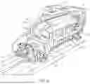


Sources:
- United States Patent and Trademark Office - verify current appl. status at the USPTO↗
Similar patent applications:
- » 20260070642
FRESH WATER MARINE FLUSHING SYSTEM AND METHOD - » 20260070645
FRESH WATER MARINE FLUSHING SYSTEM AND METHOD
Recent applications in this class:
- » 20080173589 2008-07-24
DESALINATED WATER PACKAGING - » 20080011689 2008-01-17
Desalination on an offshore apparatus - » 20080011681 2008-01-17
Desalination Method - » 20050061653 2005-03-24
Device and method for distillation - » 19031747 2025-06-17
Power and freshwater supply system for ocean integrated platform