STRUCTURED VARIABLE POROSITY MIXING AND/OR COMBUSTION DEVICE AND PROCESS
US20260071753A1
2026-03-12
19/388,298
2025-11-13
Smart Summary: A new device helps mix fluids, like in a burner, using a special structure made of layers. This structure has channels that allow fluids to flow through, and each layer has channels with different shapes. The design keeps the channels separate to reduce unwanted mixing between them. As the fluid moves through the layers, the size of the channels can change or split into smaller paths. This setup improves the efficiency of mixing and combustion processes. 🚀 TL;DR
Abstract:
A porous matrix structure for fluid mixing, such as for a burner. The matrix structure includes contiguous fluid flow channels extending through two or more matrix layers or sections. Each of the contiguous fluid flow channels comprises a different channel configuration in each of the two or more layers. Each of the contiguous fluid flow channels is separate from adjacent contiguous fluid flow channels to minimize cross flow. Each fluid flow channel changes in size and/or is divided into subchannels at each layer change.
Inventors:
- David CYGAN 11 🇺🇸 Villa Park, IL, United States
- Hamid ABBASI 10 🇺🇸 Naperville, IL, United States
- John WAGNER 3 🇺🇸 La Grange, IL, United States
- Sandeep ALAVANDI 6 🇺🇸 Schaumburg, IL, United States
Assignee:
- UTILIZATION TECHNOLOGY DEVELOPEMENT, NFP 1 🇺🇸 DES PLAINES, IL, United States
Applicant:
Interested in similar patents?
Get notified when new applications in this technology area are published.
Classification:
F23D14/84 » CPC main
Burners for combustion of a gas, e.g. of a gas stored under pressure as a liquid; Details, e.g. noise reduction means Flame spreading or otherwise shaping
F23D14/62 » CPC further
Burners for combustion of a gas, e.g. of a gas stored under pressure as a liquid; Details, e.g. noise reduction means Mixing devices; Mixing tubes
Description
CROSS REFERENCE TO RELATED APPLICATION
This application claims the benefit of U.S. Provisional Patent Application Ser. No. 63/565,139, filed on 14 Mar. 2024. The co-pending provisional application is hereby incorporated by reference herein in its entirety and is made a part hereof, including but not limited to those portions which specifically appear hereinafter.
BACKGROUND OF THE INVENTION
Field of the Invention
The invention relates generally to fluid mixing and combustion devices or burners, and more particularly to a device-structured variable porosity matrix for fluid mixing, pre-combustion mixing (e.g., fuel and oxidant), and/or fuel combustion and related processes.
Description of Related Art
A variety of porous matrix structures are available for both mixing and combustion using ceramic, metallic or composite materials. In most cases, these have random pores both along and across the flow path. There are also structured honeycomb designs mostly using ceramic.
Although two layer structures exist, current technologies using more than one layer of matrix for mixing and combustion are not structured and cannot provide the cross sectional flow control possible with this invention. A need therefore exists for a porous matrix structure for fluid flow that includes a variable internal structure along the fluid flow path to improve mixing and facilitate a stable flame.
SUMMARY OF THE INVENTION
The invention generally relates to a matrix structure, generally referred to herein as a porous matrix, which provides contiguous flow channels through multiple layers, such as for minimizing any potential for cross flow. Each flow channel can be identical, or the channel structures can be varied both across the matrix as well as along the flow path through two or more fully joined layers. As used herein “layer” refers to a section of the matrix having a different or unique channel configuration. For example, a first layer has a first channel configuration and an adjacent second layer has a second, or change in, channel configuration. The layers are generally upstream/downstream from each other in a fluid-flow direction. The invention is not limited to a number of layers, and the channel structures can vary across or within each layer. Each layer can be formed of a same or different matrix material, and the matrix material can vary across or within each layer.
The described structure allows modification of the incoming flow profile to generate a wide range of mixing, velocity and, when used in combustion, flame profiles at the exit. The multilayer design increases mixing while minimizing pressure drop and allows either relatively high velocity flames with cooler surface at its exit or embedded flame proximate exit of the matrix for increased radiation while minimizing potential for flashback. This will be especially beneficial for high flame velocity fuels such as hydrogen which are prone to flashback.
The invention is particularly suited for mixing of gases and liquids and surface combustion of gaseous fuels. The invention will allow increased radiation from the combustion side of the matrix while minimizing potential for flash back. Because of its structured design, it should allow generating a wide range of mixing and/or flame profiles across its surface and dampen or exaggerate incoming velocity profiles as the gases go through the matrix structure. In mixing applications, the invention increases formation of eddies to improve localized recirculation zones and turbulence for increased mixing through two or more stages. For combustion, the pores at its exit act as mini flame holders while the interior smaller pores with higher surface act as flame arrestor. The matrix structure can also be used in both directions to provide different mixing and flame characteristics. Using 3D printing/additive manufacturing, the pore structure can be precisely controlled to provide wide range of sizes, shapes, and contours which can be kept uniform or vary along/across the flow path.
The invention includes a porous matrix structure with contiguous fluid flow channels extending through two or more layers, wherein each of the contiguous fluid flow channels comprises a different channel configuration in each of the two or more layers. In embodiments, the change(s) in the fluid flow channels define the change in layer of the porous matrix structure.
The invention further includes a porous matrix structure including a first matrix material layer and a second matrix material layer. Contiguous fluid flow channels extend through the first matrix material layer and the second matrix material layers. Each of the contiguous fluid flow channels includes a first channel configuration within the first matrix material layer and a second channel configuration within the second matrix material layer.
In embodiments, each of the contiguous fluid flow channels is separate from adjacent contiguous fluid flow channels to minimize cross flow within each layer.
In embodiments, each of the contiguous fluid flow channels includes fluid flow subchannels in one of the two or more layers.
In embodiments, each of the contiguous fluid flow channels includes a first configuration in a first layer and a second configuration in a second layer, and the second configuration includes inner dividing walls within the contiguous fluid flow channels. As an example, the first configuration can include a single fluid flow channel, and the second configuration includes two or more fluid flow subchannels.
In embodiments, the different configuration in each of the two or more layers comprises a different size and/or different channel divisions. As an example, in embodiments, the porous matrix structure includes a first matrix material layer and a second matrix material layer adjacent the first matrix material layer, wherein each of the contiguous fluid flow channels is divided into two fluid flow subchannels within the second matrix material layer. In further embodiments, a third matrix material layer is adjacent to the second matrix material layer, wherein each of the contiguous fluid flow channels is divided further into four fluid flow subchannels within the third matrix material layer.
In embodiments, the porous matrix structure includes an array of the contiguous fluid flow channels, wherein a first section of the array includes contiguous fluid flow channels having a first fluid flow subchannel configuration, and a second section of the array includes contiguous fluid flow channels having a second fluid flow subchannel configuration.
In embodiments, the second channel configuration has a reduced size and/or divided fluid flow subchannels, compared to the first channel configuration. In embodiments with a third matrix material layer, each, or at least some, of the contiguous fluid flow channels can include a third channel configuration within the third matrix material layer. As an example, the second channel configuration has a reduced size and/or divided fluid flow subchannels, compared to the first channel configuration, and/or the third channel configuration has a further reduced size and/or further divided fluid flow subchannels, compared to the second channel configuration.
The invention further includes a burner including the porous matrix structure described herein. In embodiments, the burner surface, or flame holder, is the matrix surface at the end of the fluid flow channels.
The invention further includes a method of delivering a fluid (e.g., gas and/or oxidant) mixture to a burner or another device. The method includes passing the fluid (gas and/or oxidant) mixture through a porous matrix structure including contiguous fluid flow channels extending through first and second matrix material layers, wherein each of the contiguous fluid flow channels comprises a first channel configuration within the first matrix material layer and a second channel configuration within the second matrix material layer.
Other objects and advantages will be apparent to those skilled in the art from the following detailed description taken in conjunction with the appended claims and drawings.
BRIEF DESCRIPTION OF THE DRAWINGS
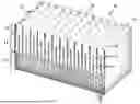
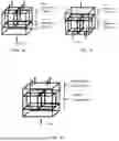
FIG. 1 is a sectional view of a three layer structure according to embodiments of this invention;
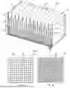
FIGS. 2A-2C show cross-sectional views of each of three layers of a lattice structure according to one embodiment;
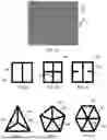
FIGS. 3A-3C show cross-sectional views of larger openings and inner dividing walls represented by the cross-sectional view of the smaller openings in an adjacent layer according to embodiments of the invention;
FIGS. 4-6 each show cross-sectional views of larger openings and inner dividing walls represented by the cross-sectional view of the smaller openings in an adjacent layer;
FIGS. 7 and 8 show velocity profiles of two preferred embodiments;
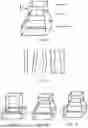
FIG. 9 shows a schematic view of one embodiment of transitions between layers;
FIG. 10 shows side view of various preferred configurations of flow channels;
FIGS. 11-13 show schematic views of various transition embodiments;
FIGS. 14 and 15 show schematics of temperature regions within two embodiments;
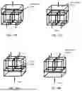
FIG. 16 shows a schematic of one preferred embodiment of a lattice structure;
FIGS. 17A and 17B shows schematics of preferred embodiments of a lattice structure;
FIGS. 18A and 18B show schematics of preferred embodiments of a lattice structure;
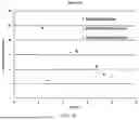
FIG. 19 shows the nitrogen oxides (NOx) emissions for the design at different excess O2 levels; and
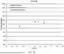
FIG. 20 shows the CO emissions for the different excess O2 levels.
DETAILED DESCRIPTION
An innovative porous matrix structure for fluid flow, particularly for gas burners, which allows varying in the internal structure along the fluid flow path to, for example, 1) generate internal eddy formations to improve mixing, and/or 2) vary the flow velocity along the flow path to facilitate flame stabilization, increased radiation or convective heat transfer from flame and when using premixed fuel and oxidant, reduction of potential for flash back. The porous matrix structure of this invention also allows profiling of flame volume and radiation and convective heat transfer across the exit of the matrix structure. The word “fluid” is used here interchangeably to describe both a single fluid and a mixture of two or more fluids, vapors, and/or gases, containing liquid droplets (e.g., a fuel and oxidant (e.g., air) mix).
While generally described herein as a combination mixer and burner, the device can be used for fluid mixing alone or for combustion of fully or partially premixed combustible fluids. The partially premixed fluids will further mix in the lattice structure to improve combustion uniformity and reduce NOx emissions.
Embodiments of this invention include a porous matrix design matched to an incoming flow profile to deliver a different flow profile at the exit. For example, a parabolic velocity profile can be converted to a relatively flat or even a reverse parabolic profile with low velocities at the center and increasing flow velocities towards the edges of the lattice cross-section. FIG. 1 is a sectional view generally illustrating a matrix 20 according to embodiments of this invention. The matrix of FIG. 1 has a three layer structure, wherein each successive layer includes, and refers to, a division of the adjacent layer with the larger openings into smaller (e.g., four) openings/quadrants.
According to preferred embodiments, such as shown in FIG. 1, the first layer 22 preferably consists of a lattice with relatively large openings 30. The second layer 24 preferably splits each of the first layer openings 30 into four equal squares 32, and the third layer 26 preferably further splits the second layer openings 32 into four equal squares 34. Depending on the thicknesses of the lattice walls, which can vary between different layers and even within the layer (both across and along the flow path), a wide variation in flow velocities between the different layers across a layer and along the flow path can be achieved.
FIGS. 2A-2C illustrate a two-dimensional cross-sectional view of the matrix such as shown in FIG. 1, using square openings (also referred to as pores) and a three layer arrangement with step changes in or approximately doubling or halving of opening or pore sizes between the layers. The openings or pores 30 are formed by walls 38. The lengths of layers are not shown, but for the purposes of concept visualization, can be assumed, as an example, to be equal for all layers and equal to five times the equivalent diameter of the largest opening. The opening or pores 30 form channels within each layer for flow of fluid. While the flow path can be in either direction—from larger to smaller opening layers and vice versa, the concept is described here with the fluid flowing into the layer with the smallest openings or layer one and then to the successively larger opening layers—layers two and three (e.g., see FIG. 1). The pores or openings 30 are formed by solid walls and form flow channels within the matrix layers. The device can be used as a mixer for two or more fluids, as a burner for combustible fluid or for both mixing and burning of combustible fluid. The flame holder surface, for example, can be an outer surface 35 of the matrix at one end of the pores or openings 30.
Various and alternative opening sizes, shapes, and combinations or configurations are available for this invention. The openings can be square, rectangular, triangular, pentagonal, hexagonal, heptagonal, octagonal etc., and can vary across a layer and between the layers. In embodiments, larger openings can be split in any number of smaller openings of varying or equal cross-section in many different patterns with fully connected or partial walls, as illustrated in FIGS. 3A-3C and 4-6 to further increase the range of achievable velocity and profiles and mixing intensities across and along the flow path providing different velocity ratios between the layers and flow profiles across the lattice. The outer boundaries 40, 50 shown in FIGS. 3A-3C and 4-6 represent the cross-sectional view of the larger openings and the inner dividing walls 42, 52 represent the cross-sectional view of the smaller openings in an adjacent layer. The opening sizes can be customized to achieve a wide range of flow profiles across the cross sec on of the lattice. By using selectively smaller openings in one or more layers, for example, a skewed or parabolic incoming flow profile can be flattened to deliver a flatter flow profile at the exit of the lattice structure or vice versa. This can also be accomplished by selectively not splitting some of the openings to maintain a larger opening size and reduce the pressure drop, such as shown in one embodiment in FIGS. 7 and 8.
The openings can also change shape within the layer or between layers, for example from rectangular to square as shown in FIG. 9. Alternatively, the channels can be straight, angled, twisted, spiral or wavy etc. as shown in various embodiments in FIG. 10. The transitions between the layers can be stepped, angled or smooth as illustrated in various embodiments shown in FIGS. 11-13.
The matrix material can be metal, alloy, ceramic, composite, and for low temperature applications, it can be plastic and selected from many other suitable materials. Part or all of the surfaces of at least a portion of at least one layer can be coated with same or different material, including catalytic or modified with projections and/or cavities to create localized mini eddies to increase fluid mixing and/or flame stabilization. The material can be changed along the flow path within each layer along and/or across the flow path or between layers to achieve desired at least one of fluid mixing and flame retention characteristics. For example, if used for combustion, the lattice structure proximate the combustion end could be made with a higher temperature material, while lower temperature materials could be used in the cooler zones, such as shown in FIGS. 14 and 15. Combustion occurs at the proximate exit and can initiate within the pores, thereby forming a burner.
Continual ongoing improvements in 3D printing/additive manufacturing technology simplifies implementation of above variations in the lattice structure and reduce manufacturing time and cost. Depending on the application, the flow of fluids through the layers could be in either direction, from larger to smaller hole layers or vice versa. Also, the walls could only cover a portion of the length of one or more layers, such as shown in FIG. 16.
FIG. 17A illustrates an example of the lattice structure for fluid mixing wherein the flow is from the smaller hole to the larger hole lattice layer. Here, as the fluid expands from the smaller holes into the larger holes, eddies are created, which increase mixing of fluid components resulting in a more thoroughly mixed fluid exiting the lattice. FIG. 17B illustrates an example of the lattice structure for fluid for combustion wherein the flow is from the smaller hole to the larger hole lattice layer. Here, the fluid components are more thoroughly mixed along the flow path as described for FIG. 17A, if not already fully premixed, and exit the larger holes at lower velocities which allows for the flame to attach to the surface of the exit holes. This results in heating of the walls of the exit holes which then reradiate to increase radiation to the workspace. The smaller holes upstream with increased surface area in contact with the flowing fluid resulting from the dividing walls increases cooling and reduces potential for flashback into upstream zones.
FIG. 18A illustrates an example of the lattice structure for fluid mixing wherein the flow is from the larger hole to the smaller hole lattice layer. Here, the dividing walls of the downstream smaller hole layer act as bluff bodies, creating localized eddies to increase mixing of the fluid components resulting in a more thoroughly mixed fluid exiting the lattice. FIG. 18B illustrates an example of the lattice structure for fluid for combustion wherein the flow fluid components containing at least one oxidant and at least one combustible fluid is from the larger hole to the smaller hole lattice layer. Here, the fluid components are more thoroughly mixed along the flow path as compared to the embodiment referenced in FIG. 18A, if not already fully premixed, and exit the smaller holes at a high velocity which creates a high momentum flame and reduces potential for flashback into the matrix. This arrangement could be particularly useful in flame treating applications with precisely profiled flames.
In preferred embodiments, the dividing walls can be designed and configured to achieve the desired mixing and/or combustion performance while minimizing pressure drop. As described above, both mixing and combustion can be combined in the same lattice structure. For example, combustible gas and oxidant can be introduced into the lattice structure simultaneously to mix within the lattice pores and burn at the exit of the structure. The combustible gas can be any gaseous fluid containing combustible components. These include methane, ethane, propane, hydrogen, ammonia, ammonia, and vapors of oils, alcohols and di methyl ether, etc. The oxidant can be any gaseous fluid containing oxygen, such as air, oxygen-enriched air, vitiated air, recirculated flue gases. The device will also be suitable for mixing and/or combustion of vaporized or atomized liquid fuel. The liquid fuel vapor or droplets can be evaporated within the lattice structure.
FIG. 19 shows the nitrogen oxides (NOx) emissions for a design of this invention at different excess O2 levels. FIG. 20 shows the CO emissions for the different excess O2 levels. The subject design produces ultra-low emissions and has good operating range with natural gas and with natural gas blended with hydrogen.
Thus the invention provides a porous matrix structure for use in adapting flow characteristic based upon need. The matrix can be, for example, 3D-printed to provide various shaped pores, such as with transitions between layers of larger and smaller pore openings or channels.
The invention illustratively disclosed herein suitably may be practiced in the absence of any element, part, step, component, or ingredient which is not specifically disclosed herein.
While in the foregoing detailed description this invention has been described in relation to certain preferred embodiments thereof, and many details have been set forth for purposes of illustration, it will be apparent to those skilled in the art that the invention is susceptible to additional embodiments and that certain of the details described herein can be varied considerably without departing from the basic principles of the invention.
Claims
What is claimed is:1. A matrix structure comprising contiguous fluid flow channels extending through two or more layers, wherein each of the contiguous fluid flow channels comprises a different channel configuration in each of the two or more layers.
2. The matrix structure of claim 1, wherein each of the contiguous fluid flow channels within a layer is separate from adjacent contiguous fluid flow channels to minimize cross flow.
3. The matrix structure of claim 1, wherein each of the contiguous fluid flow channels includes fluid flow subchannels in at least one of the two or more layers.
4. The matrix structure of claim 1, wherein each of the contiguous fluid flow channels includes a first configuration in a first layer and a second configuration in a second layer, and the second configuration includes inner dividing walls within the contiguous fluid flow channels.
5. The matrix structure of claim 4, wherein the first configuration comprises a single fluid flow channel, and the second configuration includes two or more fluid flow subchannels.
6. The matrix structure of claim 1, wherein the different configuration in each of the two or more layers comprises a different size and/or different channel divisions.
7. The matrix structure of claim 1, comprising:
a first matrix material layer; and
a second matrix material layer adjacent the first matrix material layer, wherein each of the contiguous fluid flow channels is divided into two fluid flow subchannels within the second matrix material layer.
8. The matrix structure of claim 7, further comprising:
a third matrix material layer adjacent the second matrix material layer, wherein each of the contiguous fluid flow channels is divided further into a plurality of fluid flow subchannels within the third matrix material layer.
9. The matrix structure of claim 1, further comprising an array of the contiguous fluid flow channels, wherein a first section of the array includes contiguous fluid flow channels having a first fluid flow subchannel configuration, and a second section of the array includes contiguous fluid flow channels having a second fluid flow subchannel configuration.
10. A burner or mixer comprising the porous matrix structure of claim 1.
11. A matrix structure comprising:
a first matrix material layer;
a second matrix material layer; and
contiguous fluid flow channels extending through the first matrix material layer and the second matrix material layers, wherein the each of the contiguous fluid flow channels comprises a first channel configuration within the first matrix material layer and a second channel configuration within the second matrix material layer.
12. The matrix structure of claim 11, wherein the second channel configuration has a reduced size and/or divided fluid flow subchannels, compared to the first channel configuration.
13. The matrix structure of claim 11, further comprising:
a third matrix material layer; and
each of the contiguous fluid flow channels comprises a third channel configuration within the third matrix material layer.
14. The matrix structure of claim 13, wherein the second channel configuration has a reduced size and/or divided fluid flow subchannels, compared to the first channel configuration, and the third channel configuration has a further reduced size and/or further divided fluid flow subchannels, compared to the second channel configuration.
15. The matrix structure of claim 11, wherein the each of the contiguous fluid flow channels is separate from adjacent contiguous fluid flow channels to minimize cross flow.
16. The matrix structure of claim 11, wherein each of the contiguous fluid flow channels includes fluid flow subchannels within the second channel configuration.
17. The matrix structure of claim 11, wherein the first channel configuration comprises a single flow channel, and the second channel configuration includes two or more fluid flow subchannels.
18. The matrix structure of claim 11, wherein each of the contiguous fluid flow channels includes inner dividing walls forming the second channel configuration.
19. The matrix structure of claim 11, further comprising
a third matrix material layer, wherein each of the contiguous fluid flow channels comprises a third channel configuration within the third matrix material layer;
wherein the first channel configuration includes a single fluid flow channel, the second channel configurations includes two fluid flow subchannels, and the third channel configuration includes four fluid flow subchannels.
20. A method of delivering a gas and/or oxidant mixture to a burner, the method comprising passing the gas and/or oxidant mixture through a matrix structure including contiguous fluid flow channels extending through first and second matrix material layers, wherein each of the contiguous fluid flow channels comprises a first channel configuration within the first matrix material layer and a second channel configuration within the second matrix material layer.
Images & Drawings included:

Sources:
- United States Patent and Trademark Office - verify current appl. status at the USPTO↗
Recent applications in this class:
- » 20250321001 2025-10-16
STACKED BURNER WITH CHANNEL FOR IMPROVED IGNITION - » 20240159394 2024-05-16
Gas Burner with Secondary and Tertiary Air Supplies - » 20240003539 2024-01-04
BURNER AND METHOD FOR TRANSIENT HEATING - » 20210372612 2021-12-02
Controlled secondary air supply range burner - » 20200363059 2020-11-19
OXYGEN-ENRICHED BURNER AND METHOD FOR HEATING USING OXYGEN-ENRICHED BURNER - » 20200182461 2020-06-11
OXYGEN ENRICHED BURNER AND HEATING METHOD USING OXYGEN ENRICHED BURNER - » 20200158333 2020-05-21
Burner and method for heating using burner - » 20200116351 2020-04-16
Optimized burners for boiler applications - » 20200088404 2020-03-19
Burner - » 20190186734 2019-06-20
Method and apparatus for distributing heat from a burner