Compact Freezer Unit
US20260071804A1
2026-03-12
19/323,347
2025-09-09
Smart Summary: A compact freezer unit is designed to provide cool air inside a building. It has a housing that holds various parts, including coils and fans for cooling, a special compressor, and a heater to prevent ice buildup. The unit uses sensors to monitor conditions and send signals to a controller for better performance. It also includes pipes that connect the cooling parts to circulate refrigerant. Overall, this freezer unit is efficient and space-saving, making it suitable for different structures. 🚀 TL;DR
Abstract:
A compact freezer unit for supplying conditioned air to the interior of a structure is provided herein. The compact freezer unit includes a housing containing one or more components of the freezer unit, the housing having dimensions of height, width, and depth. The components include an evaporator comprising one or more coils and an evaporator fan, a condenser and a condenser fan, a Direct Current (DC) Enhanced Vapor Injection (EVI) inverter compressor, an economizer for separating liquid and vapor refrigerant, a 4-way valve and a chassis belt electric heater configured to defrost one or more surfaces, one or more sensors for sensing a condition and generating an output signal received by a controller, and a plurality of refrigerant lines fluidly connecting the condenser and the evaporator.
Applicant:
Interested in similar patents?
Get notified when new applications in this technology area are published.
Classification:
F25D11/00 » CPC main
Devices associated with refrigerating machinery
F25D11/00 » CPC main
Self-contained movable devices, e.g. domestic refrigerators
F25D17/06 » CPC further
Arrangements for circulating cooling fluids; Arrangements for circulating gas, e.g. air, within refrigerated spaces for circulating air, e.g. by convection by forced circulation
F25D21/08 » CPC further
Defrosting; Preventing frosting; Removing condensed or defrost water; Removing frost by electric heating
F25D29/008 » CPC further
Arrangement or mounting of control or safety devices Alarm devices
F25D2700/10 » CPC further
Means for sensing or measuring; Sensors therefor Sensors measuring the temperature of the evaporator
F25D29/00 IPC
Arrangement or mounting of control or safety devices
Description
CROSS-REFERENCE TO RELATED APPLICATIONS
This application claims priority to U.S. Provisional Application No. 63/692,489, filed Sep. 9, 2024, which is hereby incorporated by reference in its entirety.
FIELD OF INVENTION
The present disclosure relates to compact refrigeration and cooling systems, and more particularly to a window-type freezer unit with enhanced vapor injection compressor technology, hybrid power supply capability, and advanced defrosting systems for producing conditioned air at temperatures of 36° F. or lower.
BACKGROUND
The global cold storage and refrigeration market has experienced substantial growth in recent years, driven by increasing demand for food preservation, pharmaceutical storage, and specialized cooling applications. This expansion has created a growing need for compact, energy-efficient refrigeration solutions that can operate in diverse environments and installation scenarios.
Traditional refrigeration systems often face limitations in terms of installation flexibility, energy consumption, and operational reliability. Many existing units are designed for specific installation types, such as walk-in coolers or large commercial freezers, leaving gaps in the market for versatile, compact solutions that can adapt to various space constraints and power supply conditions.
The rise of distributed cold storage networks, small-scale food service operations, and specialized cooling applications has highlighted the demand for refrigeration units that can achieve very low temperatures while maintaining compact form factors. These applications often require units that can fit through standard doorways, operate in challenging electrical environments, and provide reliable performance with minimal maintenance. Installation constraints in existing buildings and retrofit applications create additional challenges for refrigeration system deployment. Additionally, the need for ductwork connections to serve remote areas adds complexity to installation requirements and system design.
Energy efficiency has become increasingly important as operators seek to reduce operational costs and environmental impact. The integration of advanced compressor technologies, variable-speed components, and intelligent control systems represents a growing trend in the refrigeration industry. However, many existing compact units struggle to achieve the combination of low-temperature capability, energy efficiency, and installation flexibility that modern applications demand.
Power supply flexibility has emerged as another area of concern, particularly in applications where grid power may be unreliable or where renewable energy sources are preferred. The ability to operate on multiple power sources, including DC power from solar installations or battery systems, represents an unmet need in many market segments.
Defrosting performance in low-temperature applications remains a technical challenge that affects both energy efficiency and operational reliability. Traditional electric defrost systems consume substantial energy and may not provide uniform heating across evaporator surfaces, leading to incomplete defrost cycles and reduced system performance.
SUMMARY
This summary is provided to introduce a selection of concepts in a simplified form that are further described below in the detailed description. This summary is not intended to identify key features or essential features of the claimed subject matter, nor is it intended to be used as an aid in determining the scope of the claimed subject matter.
According to an aspect of the present disclosure, a compact freezer unit for supplying conditioned air to an interior of a structure is provided. The compact freezer unit comprises a housing containing one or more components of the freezer unit, the housing having dimensions of height, width, and depth, wherein at least two of the dimensions are less than 35 inches. The components comprise an evaporator comprising one or more coils and an evaporator fan, a condenser and a condenser fan, a Direct Current (DC) Enhanced Vapor Injection (EVI) inverter compressor, an economizer for separating liquid and vapor refrigerant, a 4-way valve and a chassis belt electric heater configured to defrost one or more surfaces, one or more sensors for sensing a condition and generating an output signal received by a controller, and a plurality of refrigerant lines fluidly connecting the condenser and the evaporator. The unit is capable of producing conditioned air having a temperature of 10° F. or lower when the conditioned air exits the compact freezer unit.
According to other aspects of the present disclosure, the compact freezer unit may include one or more of the following features. The evaporator fan may comprise a brushless direct current motor. The condenser fan may comprise a brushless direct current motor. The unit may be configured with a hybrid power supply that is compatible with at least a prime power supply and a 200 Vdc-370 Vdc auxiliary DC power supply. The one or more sensors may include at least a defrost temperature sensor positioned about the evaporator. The 4-way valve may be configured to reverse a flow of a refrigerant in at least a portion of the plurality of refrigerant lines for defrosting a surface of the evaporator. The controller may be configured to receive an output signal of the defrost temperature sensor and direct a positioning of the 4-way valve between a cooling position and a defrost position, and the controller may be capable of switching the positioning of the 4-way valve at timed intervals. The unit may be capable of receiving power from the prime power supply or the auxiliary DC power supply individually, or both simultaneously, and the unit may be configured to generate an alarm when the prime power supply is not providing power to the unit. The unit may further comprise an economizer.
According to another aspect of the present disclosure, a compact freezer unit for supplying conditioned air to an interior of a structure is provided. The compact freezer unit comprises a housing containing one or more components of the freezer unit, the housing having dimensions of height, width, and depth, wherein at least two of the dimensions are less than 35 inches. The components comprise an evaporator comprising one or more coils and an evaporator fan, a condenser and a condenser fan, a Direct Current (DC) Enhanced Vapor Injection (EVI) inverter compressor, an economizer for separating liquid and vapor refrigerant, a 4-way valve and a chassis belt electric heater configured to defrost one or more surfaces, one or more sensors for sensing a condition and generating an output signal received by a controller, a plurality of refrigerant lines fluidly connecting the condenser and the evaporator, and a duct system for transferring air from the interior of the structure to the housing and back to the interior, wherein the duct system comprises a supply air duct and a return air duct. The unit is capable of producing conditioned air having a temperature of 10° F. or lower when the conditioned air exits the compact freezer unit.
According to other aspects of the present disclosure, the compact freezer unit may include one or more of the following features. The evaporator fan may comprise a high head pressure for moving air through at least a portion of the duct system. The evaporator fan may comprise a brushless direct current motor and the condenser fan may comprise a brushless direct current motor. The unit may be configured with a hybrid power supply that is compatible with at least a prime power supply and a 200 Vdc-370 Vdc auxiliary DC power supply. The one or more sensors may include at least a defrost temperature sensor positioned about the evaporator. The 4-way valve may be configured to reverse a flow of a refrigerant in at least a portion of the plurality of refrigerant lines for defrosting a surface of the evaporator. The controller may be configured to receive an output signal of the defrost temperature sensor and direct a positioning of the 4-way valve between a cooling position and a defrost position, and the controller may be capable of switching the positioning of the 4-way valve at timed intervals. The unit may be capable of receiving power from the prime power supply or the auxiliary DC power supply individually, or both simultaneously, and the unit may be configured to generate an alarm when the prime power supply is not providing power to the unit. The unit may further comprise an economizer. The evaporator fan may comprise a centrifugal fan capable of overcoming system resistance up to 50 Pa. The unit may be capable of supplying conditioned air at a temperature at or below −10° C.
The foregoing general description of the illustrative embodiments and the following detailed description thereof are merely exemplary aspects of the teachings of this disclosure and are not restrictive.
BRIEF DESCRIPTION OF FIGURES
Non-limiting and non-exhaustive examples are described with reference to the following figures.
FIG. 1 illustrates a schematic diagram of an embodiment of a compact freezer system.
FIG. 2 shows multiple views of one or more embodiments of a compact freezer unit.
FIG. 3 depicts a system layout of an embodiment of a compact freezer unit.
FIG. 4 illustrates a perspective view of an embodiment of a compact freezer unit showing internal component arrangement.
FIG. 5 illustrates a perspective view of an embodiment of a compact freezer unit.
FIG. 6 illustrates a perspective view of an embodiment of a compact freezer unit.
DETAILED DESCRIPTION
The following description sets forth exemplary aspects of the present disclosure. It should be recognized, however, that such description is not intended as a limitation on the scope of the present disclosure. Rather, the description also encompasses combinations and modifications to those exemplary aspects described herein.
The present disclosure relates to a compact freezer unit 100 configured for supplying conditioned air to the interior of a structure. The compact freezer unit 100 may provide cooling and freezing capabilities in various applications where space constraints and energy efficiency considerations are factors in system design. In some cases, the compact freezer unit 100 may be utilized in residential, commercial, or industrial settings where controlled temperature environments are desired.
The compact freezer unit 100 may be configured to deliver conditioned air at temperatures suitable for both standard cooling applications and specialized freezing requirements. In some cases, the compact freezer unit 100 may produce conditioned air having temperatures ranging from standard air conditioning levels down to freezing temperatures for cold storage applications. The compact freezer unit 100 may incorporate various refrigeration components and control systems to achieve the desired temperature outputs while maintaining operational efficiency.
The compact freezer unit 100 may be designed with dimensional constraints that allow for installation in locations where traditional larger refrigeration systems would not be suitable. In some cases, the compact nature of the freezer unit 100 may enable deployment in window-mounted configurations, roof-top installations, side-mount installations, or other space-limited environments. The compact freezer unit 100 may serve markets including do-it-yourself installations and replacement applications where existing infrastructure limitations affect system selection.
The compact freezer unit 100 may be configured to interface with interior structures through various air distribution methods. In some cases, the compact freezer unit 100 may provide direct air delivery to interior spaces or may be connected via duct-work systems for remote air distribution. The compact freezer unit 100 may accommodate different installation scenarios while maintaining the ability to condition air according to the thermal requirements of the served interior structure.
Referring to FIG. 1, one or more aspects of a compact freezer unit 100 may include a refrigeration system architecture configured to provide both cooling and defrosting operations through distinct flow paths. The system may incorporate a cooling flow 116 and a defrost flow 118 that operate through shared refrigeration components while providing different operational modes. In some cases, the cooling flow 116 may represent the standard refrigeration cycle path used during normal cooling operations, while the defrost flow 118 may represent an alternative flow path utilized during defrosting operations to remove ice buildup from system components, such as, for example, an evaporator, coils, and/or refrigerant lines, just to name a few.
The refrigeration system may include an evaporator 120 comprising one or more coils and an evaporator fan 121 positioned to facilitate heat exchange with air passing through the system. In some cases, the evaporator 120 may serve as the primary heat absorption component during cooling operations, where refrigerant within the coils may absorb thermal energy from the surrounding air. The evaporator fan 121 may be configured to move air across the evaporator coils to enhance heat transfer efficiency and distribute conditioned air throughout the system.
A compressor 122 may be fluidly connected to the evaporator 120 through refrigerant lines 132 to compress refrigerant vapor and circulate refrigerant throughout the system. In some cases, the compressor 122 may comprise a Direct Current (DC) Enhanced Vapor Injection (EVI) inverter compressor that provides variable capacity operation and enhanced performance characteristics. The DC EVI inverter compressor may incorporate vapor injection technology to improve cooling performance under varying load conditions and ambient temperatures.
With continued reference to FIG. 1, a condenser 124 and a condenser fan 125 may be positioned downstream of the compressor 122 to reject heat from the compressed refrigerant to the ambient environment. The condenser 124 may include coils or heat exchange surfaces where refrigerant may release thermal energy and transition from vapor to liquid phase. The condenser fan 125 may be configured to move ambient air across the condenser 124 to facilitate heat rejection and maintain proper condensing temperatures within the system.
In one or more aspects, an economizer 126 may be incorporated into the refrigeration circuit to separate liquid and vapor refrigerant phases and optimize system performance. In some cases, the economizer 126 may receive refrigerant from the condenser 124 and provide liquid refrigerant separation while allowing vapor refrigerant to return to the compressor 122. In one aspects, the economizer 126 may enhance system efficiency by ensuring that primarily liquid refrigerant flows to the evaporator 120 while preventing liquid refrigerant from entering the compressor 122.
In one or more aspects, a four-way valve 128 may be positioned within the refrigerant circuit to control the direction of refrigerant flow and enable switching between cooling and defrosting operations. As shown in FIG. 1, the four-way valve 128 may be configured to direct refrigerant flow along the cooling flow 116 path during normal cooling operations or along the defrost flow 118 path during defrosting cycles. In some cases, the four-way valve 128 may reverse the roles of the evaporator 120 and condenser 124 during defrost operations, allowing hot refrigerant gas to flow through the evaporator coils to melt accumulated ice or to preemptively defrost the components before any substantial amount of ice or frost occurs, thereby keeping the system running at a more optimal rate.
In certain aspects, the refrigeration system may incorporate various additional components connected through the refrigerant lines 132 to support system operation and control. One or more dry filters 144 may be positioned within the refrigerant circuit to remove moisture and contaminants from the refrigerant. A main valve 146 may provide flow control or isolation capabilities within the system. An enthalpy valve 150 may be included to regulate refrigerant flow based on enthalpy conditions within the system. In some aspects, the refrigerant lines 132 may comprise a plurality of refrigerant lines fluidly connecting the condenser 124 and the evaporator 120 to enable refrigerant circulation throughout the system components.
The refrigeration system may be configured to operate with various refrigerant types to achieve desired cooling performance and environmental compliance. In some cases, the system may utilize R32, R454b, or R454c refrigerant systems that provide effective heat transfer characteristics while meeting regulatory requirements for environmental impact. These refrigerant systems may offer suitable thermodynamic properties for the temperature ranges and operating conditions encountered in compact freezer applications.
The compact freezer unit 100 may incorporate one or more sensors configured to monitor various operating conditions and generate output signals for system control and monitoring functions. In some aspects, multiple sensors may be used thereby creating a sensor network having multiple temperature sensors, pressure monitoring devices, and specialized sensing components positioned throughout the refrigeration system to provide real-time feedback on system performance and operating parameters. In some cases, the sensor network may enable automated control responses, safety monitoring, and diagnostic capabilities that enhance system reliability and operational efficiency. The sensors may be configured to communicate with a controller that processes the sensor signals and implements appropriate control actions based on the monitored conditions.
In one or more aspects, a high pressure switch 130 may be positioned within the refrigeration circuit to monitor refrigerant pressure levels and provide protection against excessive system pressures. The high pressure switch 130 may be configured to generate an output signal when refrigerant pressure exceeds predetermined thresholds, allowing the controller to implement protective measures such as compressor shutdown or capacity reduction, among other actions as necessary. In some cases, the high pressure switch 130 may serve as a safety device that prevents system damage due to abnormally high operating pressures that could result from restricted airflow, ambient temperature extremes, or system malfunctions. In some aspects, a low pressure switch 134 may be positioned at a different location within the refrigeration circuit to monitor low-side pressure conditions and detect situations where refrigerant pressure falls below acceptable operating ranges.
The low pressure switch 134 may generate output signals when refrigerant pressure drops to levels that could indicate refrigerant leaks, blocked expansion devices, or other system anomalies that affect cooling performance. In some aspects, the low pressure switch 134 may work in conjunction with the high pressure switch 130 to provide comprehensive pressure monitoring across the refrigeration system. The pressure switches may be connected to the controller through electrical connections that allow rapid communication of pressure status changes and enable immediate system responses to protect components and maintain safe operating conditions.
In some aspects, temperature monitoring throughout the compact freezer unit 100 may be accomplished through one or more temperature sensors at strategic locations within the refrigeration circuit and surrounding environment. In one or more aspects, a suction temperature sensor 136 may be positioned to monitor the temperature of refrigerant vapor entering the compressor 122, providing feedback on evaporator performance and system loading conditions. The suction temperature sensor 136 may generate output signals that allow the controller to assess whether the evaporator 120 is operating within acceptable temperature ranges and whether refrigerant superheat levels are appropriate for efficient compressor operation. A discharge temperature sensor 138 may be positioned to monitor the temperature of compressed refrigerant leaving the compressor 122, enabling detection of excessive discharge temperatures that could indicate compressor stress or system inefficiencies.
The discharge temperature sensor 138 may provide output signals that enable the controller to implement protective measures when discharge temperatures exceed safe operating limits, such as reducing compressor capacity or initiating system shutdown procedures. In some aspects, the suction temperature sensor 136 and discharge temperature sensor 138 may work together to provide comprehensive monitoring of compressor operating conditions and refrigerant state changes across the compression process. An outdoor ambient temperature sensor 140 may be positioned to monitor external environmental conditions that affect system performance and heat rejection capabilities of the condenser 124.
In one or more aspects, a condenser outlet temperature sensor 142 may be positioned at the outlet of the condenser 124 to monitor the temperature of refrigerant leaving the condensing process. The condenser outlet temperature sensor 142 may generate output signals that provide feedback on condensing performance and subcooling levels within the refrigerant circuit. In some aspects, the condenser outlet temperature sensor 142 may enable the controller to optimize system operation by adjusting fan speeds, compressor capacity, or other operating parameters based on condensing conditions. The outdoor ambient temperature sensor 140 and condenser outlet temperature sensor 142 may provide coordinated monitoring of heat rejection processes and ambient conditions that influence overall system efficiency.
Defrosting operations within the compact freezer unit 100 may be monitored through one or more defrosting temperature sensor(s) 148. In some aspects, at least one defrosting temperature sensor 148 may be positioned about the evaporator 120 to detect ice accumulation and determine when defrosting cycles should be initiated or terminated. A defrosting temperature sensor 148 may generate output signals that indicate when frost or ice buildup on a component reaches levels that could impair heat transfer or airflow through the system. In some aspects, a defrosting temperature sensor 148 may enable a fixed-time interval system such that the defrosting occurs at one or more fixed time to limit or prevent ice or frost accumulation. In some aspects, demand-based defrosting control may be implemented where defrost cycles are initiated based on actual ice accumulation conditions rather than fixed time intervals. A defrosting temperature sensor 148 may work in conjunction with the four-way valve 128 to coordinate defrost operations and monitor the effectiveness of hot gas defrosting processes.
In some aspects, one or more sensors, or a sensor network, may include specialized sensor(s) for monitoring enthalpy conditions and indoor environmental parameters that affect system operation and performance. In some aspects, an enthalpy “IN” temperature sensor 152 may be positioned to monitor temperature conditions at the inlet of an enthalpy valve 150, providing feedback on refrigerant conditions entering the enthalpy control device. In some aspects, an enthalpy “OUT” temperature sensor 154 may be positioned to monitor temperature conditions at the outlet of an enthalpy valve 150, enabling assessment of the temperature change across the enthalpy control process. In some cases, an enthalpy IN temperature sensor 152 and an enthalpy OUT temperature sensor 154 may provide coordinated monitoring that allows the controller to optimize enthalpy valve operation and maintain desired refrigerant conditions throughout the system.
In some aspects, the freezer unit system may include an indoor ambient temperature sensor 156 that may be positioned to monitor the temperature of the interior space being conditioned by the compact freezer Unit 100, providing feedback on cooling performance and space temperature control. An indoor ambient temperature sensor 156 may generate output signals that enable the controller to adjust system capacity, fan speeds, or operating modes to maintain desired interior temperatures. In some cases, an indoor ambient temperature sensor 156 may work in conjunction with other temperature sensors to provide comprehensive monitoring of both system performance and environmental conditions. The sensor network may be configured to provide continuous monitoring and real-time feedback that enables automated control responses, diagnostic capabilities, and performance optimization across varying operating conditions and load requirements.
Referring now to FIG. 2, a compact freezer unit 100 of the disclosure may include a housing 158 that contains one or more components of the freezer unit and provides structural support and environmental protection for the internal refrigeration system. A housing 158 may be configured with specific dimensional constraints that enable installation in space-limited environments while maintaining the functionality of the contained refrigeration components. In some cases, a housing 158 may be constructed from materials that provide thermal insulation, structural integrity, and weather resistance suitable for various installation environments. A housing 158 as disclosed herein may incorporate access panels, mounting provisions, and interface connections that facilitate installation, functionality, and maintenance operations.
In certain aspects of this disclosure, a housing 158 may have dimensions including a width 200, a height 202, and a length 204 that define the overall physical envelope of the compact freezer unit 100. In some cases, at least two of the dimensions may be less than 48 inches, enabling the compact freezer unit 100 to fit within constrained installation spaces where larger refrigeration systems would not be suitable. In some cases, at least two of the dimensions may be less than 42 inches, less than 36 inches, less than 30 inches, less than 24 inches, or less than 18 inches. In some cases, at least one of the dimensions may be less than 48 inches, enabling the compact freezer unit 100 to fit within constrained installation spaces where larger refrigeration systems would not be suitable. In some cases, at least one of the dimensions may be less than 42 inches, less than 36 inches, less than 30 inches, less than 24 inches, less than 18 inches, or less than 12 inches. The one or more dimensions may include the width 200 which may represent the lateral dimension of the housing 158 when viewed from the front, while the height 202 may represent the vertical dimension and the length 204 may represent the depth dimension extending from front to rear. The compact dimensional configuration may allow the compact freezer unit 100 to be installed in window openings, wall penetrations, or other space-limited mounting locations while providing adequate internal volume for the refrigeration components.
As shown in FIG. 2, in some aspects as disclosed herein, the housing 158 may be configured to accommodate multiple installation orientations and mounting configurations depending on the specific application requirements. The housing 158 may include mounting provisions that enable window-type installation where the compact freezer unit 100 may be positioned within a window opening or wall aperture to provide conditioned air to an interior space. In some cases, the housing 158 may be configured as a window-type unit with freezing or below-freezing temperature capabilities for DIY and replacement markets, allowing users to install the system without extensive modifications to existing structures. The compact dimensions of the housing 158 may facilitate handling and positioning during installation while providing sufficient internal space for components such as, but not limited to, the evaporator 120, evaporator fan 121, condenser 124, condenser fan 125, compressor 122, and other refrigeration components.
In some aspects, the housing 158 may also be configured to support roof top mounting type installation where the compact freezer unit 100 may be positioned on a structures's rooftop or elevated platform to serve an interior space through duct-work connections. In some cases, the roof top mounting configuration may utilize the same housing 158 structure with additional mounting hardware or support brackets that secure the unit to roof surfaces or structural supports. The dimensional characteristics defined by the width 200, height 202, and length 204 may enable the housing 158 to be transported and positioned on rooftops using standard lifting equipment while maintaining structural stability under wind loads and environmental conditions. The housing 158 may incorporate drainage provisions, weatherproofing features, and access points that support roof top installation requirements.
With continued reference to FIG. 2, the housing 158 may be designed with a generally rectangular configuration that maximizes internal component arrangement efficiency while minimizing external dimensions. The rectangular form factor defined by the width 200, height 202, and length 204 may provide optimal space utilization for the refrigeration components while maintaining structural rigidity and manufacturing efficiency. In some cases, the housing 158 may include internal partitions or compartments that separate different functional areas such as evaporator sections, condenser sections, and electrical control areas. The compact nature of the housing 158 may enable multiple units to be installed in close proximity or connected together for applications requiring increased cooling capacity or redundant operation. In some aspects, the housing 158 may be configured in alternative geometric forms such as squre, cylindrical, oval, or custom-shaped configurations that may be optimized for specific installation requirements or aesthetic considerations. The housing 158 configuration may be adapted to accommodate unique mounting constraints, architectural features, or space limitations that may benefit from non-rectangular form factors while maintaining the functional arrangement of internal refrigeration components.
The compact freezer unit 100 may incorporate an air circulation and ventilation system configured to manage airflow between the interior structure and the refrigeration components within the housing 158. The air circulation system may facilitate the transfer of thermal energy from conditioned spaces to the evaporator 120 while distributing cooled air back to the interior environment. In some cases, the air circulation system may include multiple airflow paths that accommodate different operational modes and installation configurations. The ventilation system may provide controlled introduction of outdoor air to maintain indoor air quality while supporting the thermal conditioning processes of the refrigeration system.
In some aspects, a supply air 160 configuration may be incorporated into the housing 158 to deliver conditioned air from the evaporator 120 to the interior structure being served by the compact freezer unit 100. The supply air 160 may exit the housing 158 through openings or grilles positioned to direct cooled air into the conditioned space in a manner that promotes effective air distribution and temperature control. In some cases, the supply air 160 may be conditioned to temperatures suitable for both standard cooling applications and specialized freezing requirements. The compact freezer unit 100 may be capable of producing conditioned air having a temperature of 34° F. or lower when the conditioned air exits the compact freezer unit through the supply air 160 outlets. In some aspects, the compact freezer unit 100 may be capable of producing conditioned air having a temperature of 32° F. or lower, of 25° F. or lower, of 20° F. or lower, of 15° F. or lower, of 10° F. or lower, of 5° F. or lower, of 0° F. or lower, of −5° F. or lower, of −10° F. or lower, of −15° F. or lower, of −20° F. or lower, of −25° F. or lower, or of −30° F. or lower.
In some aspects, a return air 162 pathway may be provided to enable circulation of air from the conditioned interior space to the compact freezer unit 100 for thermal conditioning. The return air 162 may enter the housing 158 through dedicated openings that allow air from the interior structure to flow into the housing 158 and be directed to flow across the evaporator coils where thermal energy may be absorbed by the refrigerant. In some cases, the return air 162 system may be designed to maintain continuous air circulation between the interior space and the refrigeration components, enabling consistent temperature control and efficient heat transfer. The return air 162 configuration may work in coordination with the supply air 160 system to establish a closed-loop air circulation pattern that maximizes cooling effectiveness while minimizing energy consumption.
In some aspects, the evaporator fan 121 may comprise a centrifugal fan configuration that provides enhanced air movement capabilities compared to alternative fan designs. In some cases, the centrifugal fan design may be capable of overcoming system resistance up to 30 Pa, 35 Pa, 40 Pa, 45 Pa, 50 Pa, 55 Pa, 60 Pa, 65 Pa, 70 Pa, or 75 Pa, enabling the evaporator fan 121 to move air through restrictive pathways or extended ductwork connections. The evaporator fan 121 may comprise a brushless direct current motor that provides variable speed operation and enhanced efficiency characteristics. The brushless direct current motor configuration may enable precise control of airflow rates and reduce electrical power consumption compared to alternating current motor designs. The evaporator fan 121 may comprise a high head pressure capability for moving air through various system components and distribution pathways, allowing the compact freezer unit 100 to maintain adequate airflow even when system resistance increases due to filter loading, duct connections, or frost accumulation on the evaporator coils.
In certain aspects, the condenser fan 125 may be configured as an axial fan design that provides efficient air movement across the condenser 124 for heat rejection to the ambient environment. The axial fan configuration may be selected for the condenser fan 125 to optimize airflow characteristics for heat rejection applications where high static pressure capability may be less important than air volume delivery. In some cases, the condenser fan 125 may comprise a brushless direct current motor that enables variable speed operation and enhanced electrical efficiency. The brushless direct current motor design may allow the condenser fan 125 to adjust airflow rates based on ambient conditions and heat rejection requirements, optimizing system performance across varying operating conditions. The condenser fan 125 may work in coordination with the evaporator fan 121 to provide balanced air movement throughout the refrigeration system while maintaining distinct airflow characteristics appropriate for each heat exchange function.
In certain aspects, a fresh air inlet 164 may be incorporated into the housing 158 to provide controlled introduction of outdoor/environmental air into the air circulation system. The fresh air inlet 164 may be positioned on a lateral surface or other suitable location of the housing 158 to enable outdoor/environmental air to enter the system. In some aspects, the outdoor/environmental air may mix with return air 162 from the conditioned space. In some cases, the fresh air inlet 164 may be equipped with dampers, filters, or other control devices that regulate the quantity and quality of outdoor air introduced into the system. The fresh air inlet 164 may support ventilation requirements for indoor air quality while providing opportunities for economizer operation when outdoor conditions are favorable for cooling assistance. The fresh air inlet 164 may be sized and positioned to minimize adverse effects on system performance while providing adequate ventilation air for the served interior spaces.
A drainage hole 166 may be provided in the housing 158 to enable removal of condensate water that may accumulate during cooling operations. The drainage hole 166 may be positioned at a low point within the housing 158 where gravity may facilitate water drainage away from electrical components and other system elements that could be damaged by moisture accumulation. In some cases, the drainage hole 166 may be connected to internal drainage channels or collection systems that direct condensate water to the exterior of the housing 158. The drainage hole 166 may be sized to accommodate expected condensate flow rates while preventing the entry of insects, debris, or other contaminants that could affect system operation. The drainage system incorporating the drainage hole 166 may be designed to function effectively across different installation orientations and mounting configurations of the Freezer Unit 100.
In some aspects, a control panel 168 may be integrated into the housing 158 to provide user interface capabilities and system monitoring functions for the compact freezer unit 100. The control panel 168 may include displays, switches, indicators, and other interface elements that enable users to monitor system status and adjust operating parameters. In some cases, the control panel 168 may provide access to temperature settings, fan speed controls, defrost cycle management, and other operational functions. The control panel 168 may be positioned on an accessible surface of the housing 158 where users may interact with the system without requiring removal of panels or access to internal components. The control panel 168 may incorporate communication capabilities that enable remote monitoring and control functions through wireless connectivity or other communication interfaces, allowing users to manage system operation from remote locations or through mobile applications.
Referring now to FIG. 3, the Freezer Unit 100 may be configured to interface with remote cooling applications through a duct system that enables air distribution to locations separated from the housing 158. The duct system may provide a means for transferring air from the interior of a structure to the housing 158 and back to the interior, allowing the Freezer Unit 100 to serve spaces that may not be in direct proximity to the unit installation location. In some cases, the duct system may enable the Freezer Unit 100 to condition air for cold storage applications, commercial refrigeration requirements, or other specialized cooling needs where direct air delivery from the unit may not be practical or desirable. The duct system configuration may expand the installation flexibility of the Freezer Unit 100 by allowing the housing 158 to be positioned in locations that optimize access for maintenance, power connections, or environmental conditions while serving remote interior spaces.
A cold storage room 170 may represent a typical application where the Freezer Unit 100 provides conditioned air through the duct system to maintain controlled temperature environments for food storage, pharmaceutical applications, or other temperature-sensitive materials. The cold storage room 170 may be positioned at a distance from the Freezer Unit 100 that requires air distribution through duct-work connections rather than direct air delivery from the housing 158. In some cases, the cold storage room 170 may have specific temperature requirements that range from standard refrigeration temperatures to freezing conditions, depending on the stored materials and application requirements. The Freezer Unit 100 may accommodate room volumes ranging from small residential applications to larger commercial spaces based on different refrigerant system configurations and duct system designs that optimize air distribution for the served area.
The duct system may comprise a supply air duct 182 and a return air duct 184 that establish a closed-loop air circulation pathway between the Freezer Unit 100 and the cold storage room 170. The supply air duct 182 may carry conditioned air from the evaporator 120 and evaporator fan 121 within the housing 158 to the cold storage room 170, delivering cooled air at temperatures suitable for the intended application. In some cases, the supply air duct 182 may be sized and configured to maintain adequate airflow rates and minimize pressure losses that could reduce system performance or increase energy consumption. The supply air duct 182 may incorporate insulation materials to prevent thermal gains that could warm the conditioned air during transport from the Freezer Unit 100 to the cold storage room 170.
The return air duct 184 may provide a pathway for air to flow from the cold storage room 170 back to the evaporator 120 within the housing 158, completing the air circulation loop and enabling continuous heat removal from the conditioned space. The return air duct 184 may be configured to collect air from the cold storage room 170 and transport the air back to the evaporator fan 121 where thermal conditioning may occur through heat exchange with the refrigerant in the evaporator coils. In some cases, the return air duct 184 may be designed to minimize air leakage and maintain proper air circulation rates that support effective temperature control within the cold storage room 170. The return air duct 184 may work in coordination with the supply air duct 182 to establish balanced airflow that prevents pressure imbalances or circulation problems that could affect cooling performance.
In one or more aspects the duct system may incorporate curved ductwork 176 that enables the supply air duct 182 and return air duct 184 to navigate around obstacles, change direction, or accommodate building structural elements between the Freezer Unit 100 and the cold storage room 170. The curved ductwork 176 may provide installation flexibility by allowing the duct system to follow available pathways through buildings, around equipment, or through structural openings that may not provide straight-line connections between the unit and the served space. In some cases, the curved ductwork 176 may introduce additional pressure losses and flow resistance that may affect the performance of the evaporator fan 121 and overall air circulation rates through the system. The curved ductwork 176 configuration may influence the maximum distance capabilities of the duct system and may require consideration during system design to ensure adequate airflow delivery to the cold storage room 170.
In some aspects, the duct system may be subject to distance limitations that affect the ability of the evaporator fan 121 to maintain adequate airflow through the supply air duct 182 and return air duct 184. In some cases, the maximum distance for efficiency and operation of the the Freczer Unit 100 may be approximately 50 feet. The distance limitations may be influenced by the high head pressure capabilities of the evaporator fan 121, which may be capable of overcoming system resistance, for example, up to 50 Pa, to maintain airflow through extended ductwork connections.
In one or more aspects, multiple Freezer Units 100 may be utilized together in applications where increased cooling capacity or redundant operation may be desired for larger cold storage rooms 170 or commercial installations. The multiple unit configuration may be controlled by a common control system or multi-control configuration that coordinates the operation of individual units to provide balanced cooling and efficient system performance. In some cases, multiple Freezer Units 100 may be connected to separate duct systems that serve different zones within a larger cold storage facility, or multiple units may be connected to a common duct system with appropriate airflow balancing and control provisions. The multi-unit configuration may enable the system to accommodate larger room volumes and provide operational flexibility through individual unit control, maintenance scheduling, and capacity modulation based on varying cooling loads or seasonal requirements.
Referring now to FIG. 4, in one or more aspects disclosed herein, the internal arrangement of components within the housing 158 may be configured to optimize space utilization while maintaining accessibility for service and operational efficiency. The housing 158 may provide a configuration that accommodates the evaporator 120, compressor 122, condenser 124, and associated fan assemblies in a compact arrangement suitable for various installation applications. In some cases, the internal component layout may be designed to minimize refrigerant line lengths while providing adequate airflow pathways for both the evaporator fan 121 and condenser fan 125. The spatial organization within the housing 158 may facilitate heat transfer processes while maintaining separation between different functional areas to prevent thermal interference between components.
In some aspects, the evaporator 120 and evaporator fan 121 may be positioned in one section of the housing 158 where conditioned air circulation may occur through the supply air 160 and return air 162 pathways. The evaporator 120 may be mounted within the housing 158 to provide optimal air contact with the refrigerant coils while allowing the evaporator fan 121 to draw air through the heat exchange surfaces effectively. In some aspects, the evaporator 120 may utilize a high-efficiency design with reduced fin pitch that increases the heat transfer surface area within the available space constraints of the housing 158. The reduced fin pitch configuration may be enabled by the high head pressure capabilities of the evaporator fan 121, which may overcome the increased airflow resistance created by the closer fin spacing. The evaporator fan 121 may be positioned to provide uniform air distribution across the evaporator coils while maintaining adequate clearance for air movement and component access.
With continued reference to FIG. 4, in some aspects the condenser 124 and compressor 122 may be arranged in another section of the housing 158 where heat rejection and refrigerant compression functions may be performed. The compressor 122 may be mounted within the housing 158 using vibration isolation provisions that minimize noise transmission and structural vibration while providing secure positioning for reliable operation. In some cases, the compressor 122 mounting arrangement may allow for thermal expansion and contraction while maintaining proper alignment with connected refrigerant lines and electrical connections. The condenser 124 may be positioned within the housing 158 to facilitate heat rejection to the ambient environment through airflow provided by the condenser fan 125, with adequate clearance around the condenser coils to prevent airflow restriction or recirculation of heated air.
In certain aspects, the arrangement of components within the housing 158 may provide distinct airflow pathways that prevent mixing of conditioned air and ambient air streams while maintaining efficient heat transfer for both evaporator and condenser functions. The evaporator section may be configured to handle the supply air 160 and return air 162 circulation without interference from the heat rejection airflow associated with the condenser 124. In some cases, internal partitions or airflow guides within the housing 158 may direct air movement through appropriate pathways while preventing short-circuiting of airflow between different functional areas. The spatial separation of components may also facilitate maintenance access by providing clear pathways to individual components without requiring removal of adjacent equipment.
As shown in FIG. 5, in certain aspects the housing 158 may accommodate the evaporator fan 121 and condenser fan 125 in positions that optimize their respective airflow functions while maintaining the compact overall dimensions of the Freezer Unit 100. The evaporator fan 121 may be mounted within the housing 158 to provide effective air movement through the evaporator section while accommodating the fresh air inlet 164 that enables controlled introduction of outdoor air into the system. The fan mounting arrangements may provide secure positioning while allowing for operational vibration and thermal expansion without affecting performance or creating noise issues. In some cases, the fan assemblies may be positioned to minimize interference with other components while providing adequate service access for maintenance or replacement operations.
In some aspects, the fresh air inlet 164 may be integrated into the housing 158 design to work in coordination with the internal component arrangement and airflow pathways established by the evaporator fan 121. The positioning of the fresh air inlet 164 on a side surface of the housing 158 may enable outdoor air introduction without disrupting the primary air circulation patterns between the evaporator 120 and the conditioned space. In some cases, the fresh air inlet 164 may be located to minimize pressure losses and airflow turbulence while providing adequate mixing of outdoor air with return air from the conditioned space. The internal arrangement may accommodate dampers or control devices associated with the fresh air inlet 164 without interfering with other component functions or service access requirements.
Referring now to FIG. 6, in some aspects as disclosed herein, the housing 158 may be configured with supply air 160 and return air 162 openings positioned on the front portion of the housing to facilitate direct air exchange with conditioned spaces or connection to duct-work systems. The internal component arrangement may support both direct air delivery applications and ducted air distribution through the same housing configuration and component layout. The supply air 160 and return air 162 openings may be sized and positioned to work effectively with the internal airflow pathways created by the evaporator fan 121 and evaporator 120 arrangement. In some cases, the front-mounted air openings may provide installation flexibility by allowing the housing 158 to be oriented in different positions while maintaining proper airflow direction and distribution characteristics.
The integration of the fresh air inlet 164 on the side surface of the housing 158 may complement the front-mounted supply air 160 and return air 162 configuration by providing outdoor air introduction capabilities without interfering with the primary air circulation functions. The internal component arrangement may accommodate the multiple airflow pathways required for supply air delivery, return air collection, and fresh air introduction while maintaining compact dimensions and efficient space utilization. In some cases, the component positioning within the housing 158 may enable the system to function effectively across different installation orientations and mounting configurations while preserving the intended airflow patterns and heat transfer characteristics of the refrigeration system.
In certain aspects, the Freezer Unit 100 may incorporate a defrosting system that combines multiple defrosting mechanisms to provide enhanced ice removal capabilities while maintaining energy efficiency during defrost operations. The defrosting system may utilize both hot gas defrosting through refrigerant flow reversal and supplemental electric heating to ensure ice removal/prevention from system surfaces under varying operating conditions. In some cases, the dual defrosting approach may provide more reliable defrost performance compared to systems that rely on a single defrosting method, particularly in applications where ice accumulation may be substantial or where ambient conditions may affect defrost effectiveness. The defrosting system may be configured to operate automatically based on system monitoring and control logic that determines when defrost cycles are needed and coordinates the operation of multiple defrosting components based on the parameters and requirements of the system.
In certain aspects, the four-way valve 128 may be utilized as a component for implementing hot gas defrosting by reversing the flow of refrigerant in at least a portion of the plurality of refrigerant lines during defrost operations. During normal cooling operations, the four-way valve 128 may be positioned in a cooling position where refrigerant flow follows the cooling flow 116 path, with the evaporator 120 functioning as the heat absorption component and the condenser 124 functioning as the heat rejection component. When defrost operations are initiated, the four-way valve 128 may be repositioned to a defrost position where refrigerant flow follows the defrost flow 118 path, effectively reversing the roles of the evaporator 120 and condenser 124. In the defrost position, hot refrigerant gas from the compressor 122 may be directed to flow through the evaporator 120, providing thermal energy to melt ice accumulation on the evaporator coils and associated surfaces.
The hot gas defrosting process may provide efficient ice/frost removal by utilizing the thermal energy already present in the compressed refrigerant rather than relying solely on external heating elements. During defrost operations following the defrost flow 118 path, the evaporator 120 may receive hot refrigerant gas that transfers thermal energy to the coil surfaces and accumulated ice/frost, causing the ice/frost to melt and drain away from the system. The condenser 124 may temporarily function as an evaporator during the defrost cycle, absorbing thermal energy from the ambient environment to support the refrigeration cycle operation. In some cases, the hot gas defrosting method may provide faster ice removal and lower energy consumption compared to electric defrosting methods, as the thermal energy for melting ice may be derived from the refrigeration cycle rather than from separate electrical heating elements. It will also be appreciated that the defrosting process may be implemented before substantial ice/frost accumulation occurs, thereby limiting the inefficient operation of the unit. It may be advantageous to monitor the system and/or particular components for conditions that lead to, or indicate, ice/frost buildup is occurring or likely to occur, and therefore implement the defrost process to prevent such buildup conditions from occurring.
In certain aspects, a chassis belt electric heater may be incorporated into the defrosting system to provide supplemental heating capabilities that complement the hot gas defrosting function of the four-way valve 128. The chassis belt electric heater may be positioned around or adjacent to components where ice/frost accumulation may occur, providing localized heating to areas that may not receive adequate thermal energy from the hot gas defrosting process alone. In some cases, the chassis belt electric heater may be configured to operate simultaneously with the hot gas defrosting system to ensure ice/frost removal from all system surfaces, including areas such as drain pans, housing surfaces, or component mounting areas where refrigerant circulation may not provide sufficient heating. The electric heater may provide controlled thermal energy that supplements the hot gas defrosting process and ensures reliable defrost performance under varying ice accumulation conditions. In some aspects, the chassis belt electric heater may operate independently as the primary defrosting mechanism when environmental conditions or system parameters indicate that hot gas defrosting through the four-way valve 128 may not be necessary or optimal. The electric heater may provide targeted thermal energy to specific system areas where ice/frost prevention or removal is needed while allowing the refrigeration system to continue normal cooling operations without flow reversal. In some cases, the independent electric heater operation may be selected when ambient temperatures are moderate, ice accumulation is minimal, or when continuous cooling operation is prioritized over the temporary interruption that may occur during hot gas defrost cycles.
The defrosting system may be configured to defrost one or more surfaces within the Freezer Unit 100 through the coordinated operation of the four-way valve 128 and the chassis belt electric heater. The surfaces subject to defrosting may include the evaporator 120 coils, evaporator housing areas, drain components, and other system elements where ice formation may occur during normal cooling operations. The combination of hot gas defrosting and electric heating may provide comprehensive coverage of all surfaces where ice removal may be needed, ensuring that defrost operations restore full system performance and prevent ice-related operational problems. In some cases, the dual defrosting approach may be particularly effective in applications where the Freezer Unit 100 operates at very low temperatures or in high-humidity environments where ice accumulation may be more substantial than in standard air conditioning applications.
The defrosting system may incorporate control logic that manages the timing and operation of defrost cycles based on both predetermined schedules and real-time system monitoring. The controller may be configured to receive an output signal of the defrosting temperature sensor 148 and direct a positioning of the four-way valve 128 between the cooling position and the defrost position based on the sensor feedback and programmed control algorithms. The defrosting temperature sensor 148 may monitor conditions at or near the evaporator 120 to detect ice accumulation levels and determine when defrost operations should be initiated or terminated. In some cases, the controller may process the sensor signals to distinguish between normal operating conditions and conditions that indicate ice buildup that could impair system performance or airflow through the evaporator section.
The controller may be capable of switching the positioning of the four-way valve 128 at timed intervals to provide regular defrost cycles that prevent excessive ice accumulation regardless of actual ice formation rates. The timed defrosting operation may utilize predetermined intervals that are based on typical ice formation patterns and operating conditions for the intended application of the Freezer Unit 100. As one example, in some cases, the default timing for timed defrosting operations may be set at 8-hour intervals, providing regular defrost cycles that maintain system performance while minimizing unnecessary defrost operations that could reduce cooling efficiency. The timed defrosting approach may provide consistent defrost scheduling that ensures ice removal occurs before accumulation levels reach points that could significantly impact system performance or reliability. In other examples, the timing for defrosting operations may be set at 2 hours, 2.5 hours, 3 hours, 3.5 hours, 4 hours, 4.5 hours, 5 hours, 5.5 hours, 6 hours, 6.5 hours, 7 hours, 7.5 hours, 8 hours, 8.5 hours, 9 hours, 9.5 hours, 10 hours, 10.5 hours, 11 hours, 11.5 hours, 12 hours, and so on. In some aspects, one or more timing cycles may include a first default timing, and a second default timing, as determined based on environmental conditions such that the first and second timings are not the same.
In certain aspects, the defrosting system may be configured to operate on demand-based control where defrost cycles are initiated according to defrosting sensor readings rather than fixed time schedules. In certain aspects, the defrosting system may utilize both time and demand-based control operations. The demand-based defrosting operation may utilize output signals from the defrosting temperature sensor 148 to determine when actual ice accumulation conditions warrant defrost cycle initiation. The controller may monitor sensor readings continuously and compare the readings to predetermined thresholds that indicate when ice buildup has reached levels that could affect system performance. In some cases, the demand-based approach may provide more efficient defrost operation by initiating defrost cycles only when needed based on actual operating conditions, potentially reducing energy consumption and minimizing interruptions to cooling operations when ice accumulation may be minimal.
The controller may coordinate the operation of both the four-way valve 128 and the chassis belt electric heater during defrost cycles to optimize ice/frost removal effectiveness and minimize defrost cycle duration. The control logic may sequence the activation of different defrosting components to provide coordinated heating that addresses ice/frost accumulation on all affected surfaces within the system, or to prevent substantial buildup of the ice/frost on the system surfaces. In some cases, the controller may initiate hot gas defrosting through four-way valve 128 repositioning while simultaneously activating the chassis belt electric heater to provide comprehensive defrost coverage. The controller may monitor defrost progress through sensor feedback and terminate defrost operations when sensor readings indicate that ice removal has been completed and normal cooling operations may be resumed. In some cases, the controller may initiate defrosting operations which operate for a given period of time and then terminate. After termination, the controller may receive input information from one or more sensors and determine if further defrosting operations are necessary. In some aspects, a delay time period may be part of the system such that the defrosting operations terminate and cannot be commenced until the delay period is complete.
In certain aspects, the defrosting system may provide automatic transition between defrost and cooling operations without requiring manual intervention or system shutdown. When defrost operations are completed, the controller may reposition the four-way valve 128 from the defrost position back to the cooling position, restoring the normal cooling flow 116 path and returning the evaporator 120 and condenser 124 to their standard operational roles. The chassis belt electric heater may be deactivated when defrost operations are completed, allowing the system to return to normal cooling operations with minimal energy consumption for heating functions. In some cases, the automatic defrost system may provide seamless operation that maintains temperature control in the served space while ensuring that ice accumulation does not compromise system performance or reliability over extended operating periods.
In certain aspects as disclosed herein, the Freezer Unit 100 may incorporate a hybrid power supply system that enables operation from multiple power sources to enhance operational flexibility and energy efficiency. The hybrid power supply system may be configured to accept electrical power from both conventional alternating current sources and direct current sources, allowing the system to operate in applications where multiple power options may be available or where energy cost optimization may be desired. In some cases, the hybrid power supply configuration may enable the Freezer Unit 100 to integrate with renewable energy systems, backup power sources, or specialized electrical installations that provide direct current power at voltage levels suitable for refrigeration equipment operation. The hybrid power supply system may provide automatic management of power source selection and utilization to optimize energy consumption and maintain continuous operation under varying power availability conditions.
In certain aspects, the hybrid power supply system may be compatible with at least a prime power supply and an auxiliary DC power supply operating within a voltage range of 200 Vdc to 370 Vdc. The prime power supply may comprise a conventional alternating current electrical connection that provides standard electrical power from utility grid sources or building electrical systems. The prime power supply connection may enable the Freezer Unit 100 to operate in standard electrical installations without requiring specialized power conditioning or conversion equipment. In some cases, the prime power supply may serve as the primary electrical source for applications where conventional electrical power is readily available and where auxiliary power sources may not be present or may be utilized for supplemental energy supply purposes.
The auxiliary DC power supply may comprise direct current electrical sources that operate within the 200 Vdc to 370 Vdc voltage range, enabling compatibility with various renewable energy systems and specialized power sources. The auxiliary DC power supply connection may accommodate solar photovoltaic systems, battery storage systems, fuel cell systems, or other direct current power sources that generate electrical energy within the specified voltage range. In some cases, the auxiliary DC power supply capability may enable the Freezer Unit 100 to operate with reduced dependence on utility electrical power, potentially reducing operating costs and environmental impact through utilization of renewable energy sources. The voltage range specification may provide compatibility with common solar panel configurations and battery system voltages while maintaining electrical safety and system performance requirements.
In some aspects, the hybrid power supply system may be capable of receiving power from the prime power supply or the auxiliary DC power supply individually, enabling operation from either power source when the other source may not be available or when operational preferences favor utilization of a specific power source. Individual power source operation may provide operational flexibility in applications where power source availability may vary due to utility outages, renewable energy generation patterns, or maintenance requirements affecting one of the power sources. In some cases, the system may operate exclusively from the prime power supply during periods when auxiliary DC power may not be available, such as during nighttime hours when solar power generation may be absent or during periods when battery storage systems may be depleted. In some aspects, the system may operate exclusively from the auxiliary DC power supply during periods when prime power may be unavailable due to utility outages or when energy cost considerations favor utilization of stored or renewable energy sources.
In certain aspects, the hybrid power supply system may also be configured to receive power from both the prime power supply and the auxiliary DC power supply simultaneously, enabling coordinated utilization of multiple power sources to optimize energy consumption and system performance. Simultaneous power source operation may allow the system to draw electrical power from both sources according to availability and operational requirements, potentially reducing the electrical load on either individual power source while maintaining full system functionality. In some cases, simultaneous operation may enable the auxiliary DC power supply to supplement the prime power supply during periods of high electrical demand, reducing the total electrical load drawn from the utility grid while utilizing available renewable or stored energy. The simultaneous power operation capability may also provide enhanced system reliability by maintaining operation even if one power source experiences reduced capacity or temporary interruption.
The hybrid power supply system may incorporate automatic power source switching logic that manages the selection and utilization of available power sources without requiring manual intervention or system shutdown during power source transitions. The automatic switching logic may prioritize auxiliary DC power when available, enabling the system to utilize renewable energy or stored energy sources preferentially over utility grid power when such sources can meet the electrical requirements of the Freezer Unit 100. The prioritization of auxiliary DC power may provide energy cost savings and reduced environmental impact by maximizing utilization of renewable energy sources when such sources are generating electrical power. In some cases, the automatic switching logic may monitor the availability and capacity of the auxiliary DC power supply continuously and direct the system to utilize auxiliary power whenever sufficient capacity is available to meet operational requirements.
In some aspects, when auxiliary DC power capacity may be insufficient to meet the full electrical requirements of the Freezer Unit 100, the automatic switching logic may direct the system to switch to prime power or to utilize both power sources simultaneously to ensure adequate electrical supply for continued operation. The switching to prime power when needed may provide seamless operation during periods when auxiliary power sources may have reduced capacity duc to weather conditions affecting solar generation, battery depletion, or maintenance activities affecting auxiliary power systems. In some cases, the automatic switching logic may implement load management strategies that adjust system operation to match available auxiliary power capacity, such as reducing compressor speed or fan operation to operate within the available auxiliary power limits before switching to prime power sources.
The hybrid power supply system may be configured to maintain operation on auxiliary power during prime power outages, providing continued refrigeration capability even when utility electrical power may be interrupted. The ability to maintain operation during prime power outages may provide enhanced reliability for applications where temperature control may be critical, such as food storage, pharmaceutical applications, or other temperature-sensitive materials that could be damaged by extended periods without refrigeration. In some cases, the auxiliary power operation during prime power outages may enable the system to continue operating at reduced capacity levels that match the available auxiliary power supply, potentially extending the duration of operation during extended utility outages. The auxiliary power operation capability may be particularly valuable in applications where backup power sources such as battery systems or fuel cells are available to provide electrical power during emergency conditions.
In some aspects as disclosed herein, the control system may include an integrated control and drive board with DC power input system for hybrid power capability, providing the electrical interfaces and control logic necessary to manage multiple power sources and coordinate power utilization according to system requirements and power source availability. The integrated control and drive board may incorporate power conversion circuits, switching devices, and monitoring systems that enable the Freezer Unit 100 to accept electrical power from both alternating current and direct current sources while providing appropriate voltage and current conditioning for system components. In some cases, the integrated board design may provide compact packaging of power management functions while reducing the complexity of external electrical connections and installation requirements. The DC power input system may include electrical connections, protection devices, and conditioning circuits specifically designed to handle direct current power sources within the specified voltage range while maintaining electrical safety and system performance.
In some aspects of this disclosure, the hybrid power supply system may be configured to generate an alarm when the prime power supply is not providing power to the unit, enabling users or monitoring systems to be notified of utility power interruptions or prime power system malfunctions. The alarm generation capability may provide immediate notification of power source status changes that could affect system operation or indicate the need for attention to electrical supply systems. In some cases, the alarm may be communicated through visual indicators, audible signals, or electronic communication systems that alert users to the loss of prime power and the transition to auxiliary power operation. The alarm function may enable users to take appropriate actions such as checking electrical connections, contacting utility providers, or implementing additional backup power measures to ensure continued system operation during extended prime power outages.
The alarm system may differentiate between planned transitions to auxiliary power operation and unplanned loss of prime power, providing appropriate notification levels based on the nature of the power source change. Planned transitions to auxiliary power operation, such as those occurring during normal energy management operations to utilize renewable energy sources, may generate different alarm responses than unexpected prime power failures that could indicate electrical system problems. In some cases, the alarm system may provide status information about the duration of prime power outages and the remaining capacity of auxiliary power sources, enabling users to assess the situation and plan appropriate responses based on the expected duration of auxiliary power operation. The alarm generation capability may integrate with building management systems or remote monitoring systems to provide centralized notification and status reporting for multiple Freezer Unit 100 installations or complex refrigeration systems.
In some aspects as disclosed herein, the Freezer Unit 100 may be configured to deliver conditioned air across a wide range of temperatures to accommodate various cooling and freezing applications. The temperature output capabilities may extend from standard air conditioning temperatures down to extreme freezing conditions suitable for specialized cold storage requirements. In some cases, the temperature range may enable the Freezer Unit 100 to serve applications ranging from comfort cooling to food preservation, pharmaceutical storage, and industrial freezing processes. The broad temperature capability may provide operational flexibility that allows a single unit design to address multiple market segments and application requirements without requiring separate equipment configurations for different temperature ranges.
The Freezer Unit 100 may be capable of producing conditioned air having a temperature of 34° F. or lower, 20° F. or lower, 10° F. or lower, 0° F. or lower, −10° F. or lower, −20° F. or lower, or −30° F. or lower, when the conditioned air exits the compact freezer unit, enabling the system to provide freezing temperatures suitable for food storage and preservation applications. The freezing temperatures produced by the compact freezer unit 100 may allow the system to maintain temperatures that prevent bacterial growth and preserve perishable materials for extended periods. In some cases, the ability to achieve freezing temperatures or lower enable the Freezer Unit 100 to provide cold storage applications where food safety regulations require specific temperature maintenance for meat, dairy, frozen foods, and other temperature-sensitive products. The temperature capability may be maintained consistently across varying ambient conditions and system loading scenarios through the variable capacity operation of the DC EVI inverter compressor and coordinated control of system components.
The cooling capacity specifications of the Freezer Unit 100 may incorporate variable capacity operation that enables the system to adjust cooling output based on thermal load requirements and operating conditions. The variable cooling capacity may range from 2600 W to 3500 W, providing a capacity modulation range that allows the system to operate efficiently across different load conditions while maintaining temperature control performance. The lower capacity operation at 2600 W may enable the system to operate efficiently during periods of reduced thermal load, such as during cooler ambient conditions or when the conditioned space has reached target temperatures and requires only maintenance cooling. The higher capacity operation at 3500 W may provide enhanced cooling capability during periods of high thermal load, such as during initial pulldown operations, high ambient temperature conditions, or when the system serves larger conditioned spaces or higher heat load applications.
The variable capacity operation may be achieved through the inverter technology incorporated in the DC EVI compressor, which may modulate compressor speed and refrigerant flow rates to match cooling output with thermal load requirements. The capacity modulation capability may provide energy efficiency benefits by allowing the system to operate at optimal efficiency points across varying load conditions rather than cycling on and off at fixed capacity levels. In some cases, the variable capacity operation may provide more stable temperature control by enabling the system to provide continuous cooling at levels that match thermal loads, reducing temperature fluctuations that could occur with fixed capacity systems that cycle between full operation and shutdown. The capacity range may be selected to provide adequate cooling capability for the intended applications while maintaining compact dimensions and electrical power requirements suitable for the target installation environments.
For extreme freezing applications, the Freezer Unit 100 may be configured to produce supply air temperatures as low as −26° C. (−15° F.), enabling the system to serve specialized applications requiring ultra-low temperature conditions. The extreme low-temperature capability may be achieved through the enhanced vapor injection technology incorporated in the DC EVI inverter compressor, which may maintain effective refrigeration performance even under severe operating conditions where conventional compressor designs might experience reduced capacity or reliability issues. The −26° C. (−15° F.) supply air temperature capability may enable the system to serve applications such as frozen food storage, ice cream storage, pharmaceutical cold chain requirements, or industrial processes requiring sub-zero temperatures for material preservation or processing operations.
The extreme low-temperature operation may present additional challenges for system design and component selection, as refrigeration components may experience increased stress and reduced efficiency when operating at very low evaporating temperatures. The DC EVI inverter compressor technology may address these challenges through vapor injection techniques that improve compressor performance and reliability under low-temperature operating conditions. The vapor injection process may provide additional cooling to the compressor motor and compression chambers while enhancing the refrigeration cycle efficiency at low evaporating temperatures. In some cases, the enhanced vapor injection capability may enable the system to maintain adequate cooling capacity and energy efficiency even when producing supply air at −26° C. (−15° F.), conditions that might cause conventional compressor systems to experience significant performance degradation or operational difficulties.
The temperature control precision at extreme low temperatures may require sophisticated control algorithms and sensor feedback systems to maintain stable operation and prevent temperature excursions that could affect stored materials or system reliability. The control system may monitor multiple temperature points throughout the refrigeration circuit and adjust compressor capacity, fan speeds, and defrosting operations to maintain target supply air temperatures while preventing system components from operating outside acceptable ranges. The extreme low-temperature capability may also require enhanced defrosting systems to address increased ice formation rates that may occur when the evaporator operates at very low temperatures in humid environments. The combination of hot gas defrosting and electric heating elements may provide effective ice removal even under extreme operating conditions where ice accumulation rates may be higher than those encountered in standard refrigeration applications.
The cooling performance specifications may be maintained across varying ambient temperature conditions and installation environments through the adaptive control capabilities of the variable capacity refrigeration system. The system may automatically adjust cooling capacity and component operation to compensate for changes in ambient temperature, humidity levels, and thermal load conditions that could affect cooling performance. In some cases, the performance specifications may be validated across a range of operating conditions that represent typical installation environments, ensuring that the stated temperature and capacity capabilities may be achieved consistently in real-world applications. The performance validation may include testing under high ambient temperature conditions, high humidity environments, and varying electrical supply conditions to verify that the system maintains specified cooling capabilities across the expected range of operating scenarios.
The Freezer Unit 100 may incorporate advanced connectivity and control capabilities that enable remote monitoring and management through wireless communication technologies. The connectivity features may provide users with enhanced control options and system monitoring capabilities that extend beyond traditional local control interfaces. In some cases, the wireless connectivity may enable the system to communicate with external devices, networks, and cloud-based services to provide comprehensive system management and operational oversight. The connectivity capabilities may facilitate integration with building automation systems, energy management platforms, and user mobile devices to provide coordinated control and monitoring across multiple system installations or complex facility management requirements.
WiFi connectivity may be integrated into the control system to enable wireless communication between the Freezer Unit 100 and local area networks or internet-based services. The WiFi connectivity capability may provide a standardized wireless communication interface that allows the system to connect to existing wireless network infrastructure without requiring additional communication hardware or specialized network configurations. In some cases, the WiFi connectivity may enable the system to communicate through standard internet protocols and wireless security measures that provide secure data transmission and system access control. The wireless communication capability may support various network configurations including residential wireless networks, commercial building networks, and dedicated equipment networks that may be established for facility management purposes.
The WiFi connectivity may enable remote monitoring functionality that allows users to access system status information and operational data from locations remote from the physical installation of the Freezer Unit 100. Remote monitoring capabilities may provide access to temperature readings, system performance parameters, operational status indicators, and diagnostic information through wireless data transmission to connected devices or monitoring platforms. In some cases, the remote monitoring functionality may enable users to track system performance trends, identify operational anomalies, and receive notifications about system conditions that may require attention or maintenance. The monitoring data may be transmitted continuously or at predetermined intervals to provide real-time or near real-time visibility into system operation and performance characteristics.
Mobile application control capabilities may be provided through software applications designed to operate on smartphones, tablets, or other mobile computing devices that connect to the Freezer Unit 100 through the WiFi connectivity interface. The mobile application may provide a user interface that enables remote control of system functions including temperature settings, fan speed adjustments, defrost cycle management, and operational mode selection. In some cases, the mobile application interface may provide graphical displays of system status, temperature readings, and performance data that enable users to monitor and control the system through intuitive touch-screen interfaces. The mobile application control capability may enable users to adjust system operation from any location with internet connectivity, providing operational flexibility and convenience for system management.
The mobile application may incorporate user authentication and access control features that ensure secure system access and prevent unauthorized control or monitoring of the Freezer Unit 100. Security measures may include password protection, user account management, and encrypted communication protocols that protect system data and control functions from unauthorized access. In some cases, the mobile application may support multiple user accounts with different access levels, enabling facility managers to provide appropriate system access to different personnel based on their operational responsibilities. The security features may also include session management and automatic logout functions that prevent unauthorized access through unattended mobile devices.
Over-the-air update capability may be incorporated into the system to enable remote software updates and configuration changes without requiring physical access to the Freezer Unit 100 or manual installation procedures. The OTA update functionality may allow system firmware, control algorithms, and operational parameters to be updated remotely through the WiFi connectivity interface. In some cases, the OTA update capability may enable the system to receive performance improvements, feature enhancements, and security updates automatically or through user-initiated update processes. The remote update functionality may provide ongoing system improvement capabilities that extend the operational life and performance characteristics of the Freezer Unit 100 without requiring service visits or hardware modifications.
The OTA update system may incorporate verification and rollback capabilities that ensure update integrity and provide recovery options in the event that software updates may cause operational issues or compatibility problems. Update verification processes may include digital signature validation, checksum verification, and compatibility testing that confirm update packages are authentic and appropriate for the specific system configuration. In some cases, the update system may maintain backup copies of previous software versions that enable automatic or manual rollback to previous operational states if updated software may cause performance degradation or operational difficulties. The verification and rollback capabilities may provide system reliability and minimize the risk of update-related operational interruptions.
Intelligent control features may be implemented through advanced control algorithms that utilize system monitoring data and operational feedback to optimize performance and energy efficiency automatically. The intelligent control capabilities may analyze operational patterns, environmental conditions, and system performance data to adjust operational parameters without requiring manual intervention or user configuration changes. In some cases, the intelligent control system may implement predictive control strategies that anticipate cooling load changes based on historical data, ambient condition trends, and usage patterns to optimize system operation proactively. The intelligent control features may provide adaptive operation that improves system efficiency and performance over time through continuous learning and optimization processes.
The intelligent control system may incorporate fault detection and diagnostic capabilities that monitor system operation continuously and identify potential issues before operational failures may occur. Diagnostic algorithms may analyze sensor data, operational parameters, and performance trends to detect anomalies that could indicate component wear, refrigerant leaks, airflow restrictions, or other conditions that may affect system reliability or performance. In some cases, the diagnostic system may provide predictive maintenance recommendations that alert users to potential service needs based on operational data analysis and component condition assessment. The fault detection capabilities may enable proactive maintenance scheduling and reduce the likelihood of unexpected system failures or performance degradation.
Remote monitoring functionality may extend beyond basic system status reporting to include comprehensive performance analysis and energy consumption tracking that enables users to optimize operational costs and environmental impact. The monitoring system may track energy consumption patterns, operational efficiency metrics, and performance trends that provide insights into system operation and opportunities for improvement. In some cases, the remote monitoring may provide comparative analysis capabilities that benchmark system performance against expected values or similar installations to identify optimization opportunities. The performance monitoring data may be presented through graphical interfaces that enable users to visualize operational trends and make informed decisions about system operation and maintenance.
The connectivity and control features may integrate with building automation systems and energy management platforms to provide coordinated operation with other facility systems and equipment. Integration capabilities may enable the Freezer Unit 100 to participate in demand response programs, load management strategies, and facility-wide energy optimization initiatives. In some cases, the system integration may enable coordinated operation with other HVAC equipment, lighting systems, and facility management systems to optimize overall facility energy consumption and operational efficiency. The integration capabilities may support various communication protocols and data exchange formats that enable compatibility with existing building management infrastructure and third-party monitoring systems.
The economizer functionality may be enhanced through the intelligent control and connectivity features to provide optimized outdoor air utilization based on real-time weather data and indoor air quality monitoring. The connected economizer control may access external weather information and air quality data to make informed decisions about outdoor air introduction and economizer operation. In some cases, the economizer control may coordinate with the overall system operation to maximize energy savings while maintaining indoor air quality and temperature control requirements. The intelligent economizer operation may provide enhanced energy efficiency compared to traditional economizer controls by utilizing comprehensive environmental data and predictive control algorithms that optimize outdoor air utilization across varying conditions.
The dimensions and values disclosed herein are not to be understood as being strictly limited to the exact numerical values recited. Instead, unless otherwise specified, each such dimension is intended to mean both the recited value and a functionally equivalent range surrounding that value. For example, a dimension disclosed as “30 inches” is intended to mean “about 30 inches” and may include +/−1.0 inches.
A number of implementations have been described. Nevertheless, it will be understood that various modifications may be made without departing from the spirit and scope of the disclosure. Accordingly, other implementations are within the scope of the following claims.
Claims
What is claimed is:1. A compact freezer unit for supplying conditioned air to an interior of a structure, the compact freezer unit comprising:
a housing containing one or more components of the freezer unit, the housing having dimensions of height, width, and depth, wherein at least two of the dimensions are less than 35 inches,
the components comprising:
an evaporator comprising one or more coils and an evaporator fan;
a condenser and a condenser fan;
a Direct Current (DC) Enhanced Vapor Injection (EVI) inverter compressor;
an economizer for separating liquid and vapor refrigerant;
a 4-way valve and a chassis belt electric heater configured to defrost one or more surfaces;
one or more sensors for sensing a condition and generating an output signal received by a controller;
a plurality of refrigerant lines fluidly connecting the condenser and the evaporator; and
wherein the unit is capable of producing conditioned air having a temperature of 10° F. or lower when the conditioned air exits the compact freezer unit.
2. The compact freezer unit of claim 1, wherein the evaporator fan comprises a brushless direct current motor.
3. The compact freezer unit of claim 1, wherein the condenser fan comprises a brushless direct current motor.
4. The compact freezer unit of claim 1, wherein the unit is configured with a hybrid power supply that is compatible with at least a prime power supply and a 200 Vdc-370 Vdc auxiliary DC power supply.
5. The compact freezer unit of claim 1, wherein the one or more sensors includes at least a defrost temperature sensor positioned about the evaporator.
6. The compact freezer unit of claim 5, wherein the 4-way valve is configured to reverse a flow of a refrigerant in at least a portion of the plurality of refrigerant lines for defrosting a surface of the evaporator.
7. The compact freezer unit of claim 6, wherein the controller is configured to receive an output signal of the defrost temperature sensor and direct a positioning of the 4-way valve between a cooling position and a defrost position, and wherein said controller is capable of switching the positioning of the 4-way valve at timed intervals.
8. The compact freezer unit of claim 4, wherein the unit is capable of receiving power from the prime power supply or the auxiliary DC power supply individually, or both simultaneously, and the unit is configured to generate an alarm when the prime power supply is not providing power to the unit.
9. The compact freezer unit of claim 1, wherein the unit further comprises an economizer.
10. A compact freezer unit for supplying conditioned air to an interior of a structure, the compact freezer unit comprising:
a housing containing one or more components of the freezer unit, the housing having dimensions of height, width, and depth, wherein at least two of the dimensions are less than 35 inches,
the components comprising:
an evaporator comprising one or more coils and an evaporator fan;
a condenser and a condenser fan;
a Direct Current (DC) Enhanced Vapor Injection (EVI) inverter compressor;
an economizer for separating liquid and vapor refrigerant;
a 4-way valve and a chassis belt electric heater configured to defrost one or more surfaces;
one or more sensors for sensing a condition and generating an output signal received by a controller;
a plurality of refrigerant lines fluidly connecting the condenser and the evaporator; and
a duct system for transferring air from the interior of the structure to the housing and back to the interior, wherein the duct system comprises a supply air duct and a return air duct,
wherein the unit is capable of producing conditioned air having a temperature of 10° F. or lower when the conditioned air exits the compact freezer unit.
11. The compact freezer of claim 10, wherein the evaporator fan comprises a high head pressure for moving air through at least a portion of the duct system.
12. The compact freezer unit of claim 11, wherein the evaporator fan comprises a brushless direct current motor and wherein the condenser fan comprises a brushless direct current motor.
13. The compact freezer unit of claim 10, wherein the unit is configured with a hybrid power supply that is compatible with at least a prime power supply and a 200 Vdc-370 Vdc auxiliary DC power supply.
14. The compact freezer unit of claim 10, wherein the one or more sensors includes at least a defrost temperature sensor positioned about the evaporator.
15. The compact freezer unit of claim 14, wherein the 4-way valve is configured to reverse a flow of a refrigerant in at least a portion of the plurality of refrigerant lines for defrosting a surface of the evaporator.
16. The compact freezer unit of claim 15, wherein the controller is configured to receive an output signal of the defrost temperature sensor and direct a positioning of the 4-way valve between a cooling position and a defrost position, and wherein said controller is capable of switching the positioning of the 4-way valve at timed intervals.
17. The compact freezer unit of claim 13, wherein the unit is capable of receiving power from the prime power supply or the auxiliary DC power supply individually, or both simultaneously, and the unit is configured to generate an alarm when the prime power supply is not providing power to the unit.
18. The compact freezer unit of claim 10, wherein the unit further comprises an economizer.
19. The compact freezer unit of claim 10, wherein the evaporator fan comprises a centrifugal fan capable of overcoming system resistance up to 50 Pa.
20. The compact freezer unit of claim 10, wherein the unit is capable of supplying conditioned air at a temperature at or below −10° C.
Images & Drawings included:

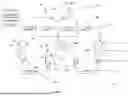


Sources:
- United States Patent and Trademark Office - verify current appl. status at the USPTO↗
Recent applications in this class:
- » 20260022882 2026-01-22
PORTABLE WATER-COOLED AIR CONDITIONER WITH A DEDICATED STORAGE COMPARTMENT FOR A HOSE KIT - » 20250377148 2025-12-11
Food Cooling Device - » 20250216142 2025-07-03
REFRIGERATOR - » 20250207840 2025-06-26
Portable Electric Cooler - » 20250189203 2025-06-12
PORTABLE CRYOGENIC COOLER CONTAINER - » 20250172328 2025-05-29
Car refrigerator installation method and installation structure - » 20250067495 2025-02-27
Refrigerated portable room system - » 20250060145 2025-02-20
REFRIGERATOR - » 20240393029 2024-11-28
BATTERY PACK-POWERED COOLER - » 20240118013 2024-04-11
Refrigerator