THERMAL TARGET APPARATUS
US20260071853A1
2026-03-12
18/829,040
2024-09-09
Smart Summary: A thermal target apparatus includes a target body with a special material on its front surface that can conduct electricity. This conductive material is connected to wires that carry electrical current from a power source. The power source can be controlled to adjust how much electricity is sent to the conductive material. When the electricity flows through, it heats up the target material. This heat makes the target visible to thermal imaging devices. 🚀 TL;DR
Abstract:
A thermal target apparatus is disclosed. In at least one embodiment, the apparatus provides at least one target body. An electrically conductive target material is positioned on a front surface of the target body. At least one length of electrically conductive delivery material is also positioned on the front surface of the target body in contact with the target material, the delivery material configured for delivering an electrical current to the target material. A power source is in electrical communication with the delivery material for selectively providing an electrical current thereto which, in turn, delivers the electrical current to the target material. A controller is in electrical communication with the power source for selectively adjusting the electrical current produced by the power source. During use, the electrical energy in the target material is converted into heat which creates a thermal target that is visible to thermal optics.
Inventors:
- Jordan Dean Zumwalt 3 🇺🇸 Roseville, CA, United States
- Calvin Caldwell 2 🇺🇸 Queen Creek, AZ, United States
Applicant:
Interested in similar patents?
Get notified when new applications in this technology area are published.
Description
RELATED APPLICATIONS
Not applicable.
BACKGROUND
The subject of this patent application relates generally to target practice systems, and more particularly to a thermal target apparatus configured for being visible to thermal optics.
Applicant(s) hereby incorporate herein by reference any and all patents and published patent applications cited or referred to in this application.
By way of background, many individuals use projectile weapons to engage in shooting sports or carry such weapons in an official capacity (e.g., law enforcement, military, etc.). Many of those individuals often wish to improve their accuracy in training scenarios that are similar to real life scenarios. Some real life scenarios may require the use of thermal optics in order to locate an object of interest (such as a person or animal, for example) using that object's persistent heat signature, such that a target configured for replicating such scenarios can be beneficial. One known prior art solution to this problem entails a target which incorporates rubber for retaining frictional heat from projectile impacts, with that heat being temporarily visible to thermal optics. However, such targets are only visible to thermal optics after being hit by at least one projectile - and even then, thermal visibility is limited to the specific locations of the target that have been hit by the at least one projectile (rather than the entire target), with that thermal visibility disappearing as the frictional heat dissipates. In other words, such known prior art targets fail to accurately mimic the thermal properties of a typical object of interest. Furthermore, such known prior art targets might not be durable enough to withstand large quantities of sustained impacts from multiple projectiles. Other known prior art solutions to this problem entail a target which utilize thermal-based chemical reactions or other materials that reflect heat or absorb light. However, such known prior art targets may also be susceptible to large quantities of sustained impacts from multiple projectiles, in addition to potentially requiring appropriate external and/or environmental conditions such as an external heat source or light source.
Thus, there remains a need for a thermal target capable of consistently mimicking an object's persistent heat signature while also being sufficiently durable for withstanding large quantities of sustained impacts from multiple projectiles. Aspects of the present invention fulfill these needs and provide further related advantages as described in the following summary.
It should be noted that the above background description includes information that may be useful in understanding aspects of the present invention. It is not an admission that any of the information provided herein is prior art or relevant to the presently claimed invention, or that any publication specifically or implicitly referenced is prior art.
SUMMARY
Aspects of the present invention teach certain benefits in construction and use which give rise to the exemplary advantages described below.
The present invention solves the problems described above by providing a thermal target apparatus. In at least one embodiment, the apparatus provides at least one target body. An electrically conductive target material is positioned on a front surface of the at least one target body. At least one length of electrically conductive delivery material is also positioned on the front surface of the at least one target body in abutting contact with the target material, the delivery material configured for delivering an electrical current to the target material. At least one power source is in electrical communication with the delivery material for selectively providing an electrical current thereto which, in turn, delivers the electrical current to the target material. At least one controller is in electrical communication with the at least one power source for selectively adjusting the electrical current produced by the at least one power source. During use, the electrical energy in the target material is converted into heat which creates a thermal target that is visible to thermal optics.
Other features and advantages of aspects of the present invention will become apparent from the following more detailed description, taken in conjunction with the accompanying drawings, which illustrate, by way of example, the principles of aspects of the invention.
BRIEF DESCRIPTION OF THE DRAWINGS
The accompanying drawings illustrate aspects of the present invention. In such drawings:
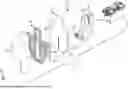
FIG. 1 is a perspective view of an exemplary thermal target apparatus, in accordance with at least one embodiment;
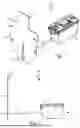
FIG. 2 is a side elevational view thereof, in accordance with at least one embodiment;
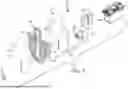
FIG. 3 is an exploded perspective view thereof, in accordance with at least one embodiment;
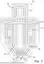
FIG. 4 is a front elevational view of a further exemplary target portion of the apparatus, in accordance with at least one embodiment; and
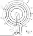
FIG. 5 is a front elevational view of a still further exemplary target portion of the apparatus, in accordance with at least one embodiment.
The above described drawing figures illustrate aspects of the invention in at least one of its exemplary embodiments, which are further defined in detail in the following description. Features, elements, and aspects of the invention that are referenced by the same numerals in different figures represent the same, equivalent, or similar features, elements, or aspects, in accordance with one or more embodiments.
DETAILED DESCRIPTION
Turning now to FIGS. 1-3, there are shown various views of an exemplary embodiment of a thermal target apparatus 20. At the outset, it should be noted that while certain embodiments of the apparatus 20 are shown and described for illustrative purposes, in further embodiments, the apparatus 20 may be configured as any other type of type of target for use in any type of target system, now known or later developed. Thus, in further embodiments, the apparatus 20 (along with each of the components described herein) may take on any other sizes, shapes, dimensions, quantities and/or configurations now known or later developed—dependent at least in part on the context in which the apparatus 20 is to be used—so long as the apparatus 20 is capable of substantially carrying out the functionality described herein.
In at least one embodiment, the apparatus 20 provides an at least one target body 22. In at least one embodiment, the at least one target body 22 is constructed out of a relatively rigid/semi-rigid but lightweight material, such as high density polyethylene (“HDPE”), corrugated plastic, polyvinyl chloride (“PVC”), or other types of plastic materials, for example. In at least one such embodiment, the at least one target body 22 is designed to be disposable and replaceable after receiving a sufficient quantity of impacts from projectiles during use of the apparatus 20. In at least one alternate embodiment, the at least one target body 22 may be constructed out of any other material or combination of materials, now known or later developed—for example, metal, wood, rubber, leather, etc. - so long as the apparatus 20 is capable of substantially carrying out the functionality described herein. In at least one further alternate embodiment, the at least one target body 22 is constructed out of one or more thermally conductive materials, such as AR500 steel for example.
In at least one embodiment, the at least one target body 22 is shaped and configured as a two-dimensional (i.e., substantially planar) target. In at least one alternate embodiment, the at least one target body 22 is shaped and configured as a three-dimensional target. In still further embodiments, the at least one target body 22 may take on any other sizes, shapes, dimensions, quantities and/or configurations now known or later developed—dependent at least in part on the context in which the apparatus 20 is to be used—so long as the apparatus 20 is capable of substantially carrying out the functionality described herein. For example, in at least one embodiment, the at least one target body 22 may be shaped so as to resemble an object of interest (e.g., human, animal, etc.).
In at least one embodiment, the apparatus 20 further provides an electrically conductive target material 24 positioned on a front surface 26 of the at least one target body 22 (i.e., the surface of the at least one target body 22 that is to receive projectile impacts) and configured for creating a thermal target that is visible to thermal optics, as discussed further below. In at least one embodiment, the target material 24 is a volume of graphite infused conductive paint. In at least one such embodiment, the conductive paint has a sheet resistance of about 55 ohms per square millimeter at a thickness of about 5 mils (or about 0.005 inches). In further such embodiments, the conductive paint may have a sheet resistance of greater than or less than 55 ohms per square millimeter. In at least one alternate embodiment, other types of electrically conductive materials, now known or later developed, capable of creating a thermal target that is visible to thermal optics, may be substituted. In at least one embodiment, the entire front surface 26 of the at least one target body 22 is covered with the target material 24. In at least one alternate embodiment, less than the entire front surface 26 of the at least one target body 22 is covered with the target material 24. In at least one such alternate embodiment, as best illustrated in FIGS. 4 and 5, the target material 24 is shaped and configured as a plurality of separate, concentrically arranged target strips 28 on the front surface 26 of the at least one target body 22. In at least one embodiment, the target strips 28 are arranged so as to form a desired target shape—such as a human torso (FIG. 4) or a traditional bullseye (FIG. 5), for example. In at least one alternate embodiment, the target strips 28 are simply arranged so as to cover a desired amount of the front surface 26 of the at least one target body 22 in a desired pattern. Thus, in further embodiments, the target material 24 may take on any other sizes, shapes, dimensions, quantities, configurations and/or relative positions on the at least one target body 22, now known or later developed, so long as the apparatus 20 is capable of substantially carrying out the functionality described herein.
In at least one embodiment, each of the target strips 28 has a surface area that is substantially equal to a surface area of each of the other target strips 28—in other words, in such embodiments, the surface areas of all target strips 28 are substantially the same. For example, in the traditional bullseye embodiment depicted in FIG. 5, while the outermost target strip 28 has a relatively larger circumference or length than the inner target strips 28, the inner target strips 28 each have a relatively larger width than the outermost target strip 28. Thus, while the sizes, shapes and/or dimensions of each of the target strips 28 might be different, they are configured in such embodiments to have substantially equal surface areas. As a result, the amount of electrical current and, in turn, thermal energy, within each of the target strips 28 is more evenly and uniformly distributed from one target strip 28 to the next, thereby creating a more uniform thermal target when the at least one target body 22 is viewed using thermal optics. In at least one alternate embodiment, one or more of the target strips 28 has a surface area that is not substantially equal to the surface area of one or more other target strips 28.
In at least one embodiment, the target strips 28 are applied to the front surface 26 of the at least one target body 22 using a silk screen printing mesh and corresponding silk screen printing methods. In at least one such embodiment, the target strips 28 have a thickness of about 0.003 inches. However, in further embodiments, the target strips 28 may have any other thickness and may be applied to the front surface 26 of the at least one target body 22 using any other methods or techniques, now known or later developed, so long as the apparatus 20 is capable of substantially carrying out the functionality described herein.
In at least one embodiment, the apparatus 20 further provides an at least one length of conductive delivery material 30 positioned on the front surface 26 of the at least one target body 22 in abutting contact with the target material 24. The delivery material 30 is configured for delivering an electrical current to the target material 24, as discussed further below. In at least one embodiment, the delivery material 30 has a resistance that is less than a resistance of the target material 24. In at least one embodiment, where the target material 24 is configured as a plurality of separate target strips 28, the delivery material 30 is in contact with opposing ends 32 of each of the target strips 28 so as to separately delivery an electrical current to the target strips 28 in parallel, thereby distributing the electrical current evenly to the target strips 28. In at least one embodiment, the delivery material 30 is an at least one strip of electrically conductive tape 34, such as copper tape for example. In at least one alternate embodiment, other types of electrically conductive delivery materials, now known or later developed, capable of delivering an electrical current to the target material 24, may be substituted. In at least one embodiment, the delivery material 30 is positioned between the target material 24 and the front surface 26 of the at least one target body 22. In at least one alternate embodiment, the target material 24 is positioned between the delivery material 30 and the front surface 26 of the at least one target body 22. Thus, in further embodiments, the delivery material 30 may take on any other sizes, shapes, dimensions, quantities, configurations and/or relative positions on the at least one target body 22, now known or later developed, so long as the apparatus 20 is capable of substantially carrying out the functionality described herein.
In at least one embodiment, as best illustrated in FIGS. 1 and 3, the apparatus 20 further provides an at least one cover layer 36 positioned overtop of the target material 24 (and, in at least one such embodiment, overtop of the delivery material 30 as well), so as to substantially sandwich the target material 24 (and delivery material 30 in at least one such embodiment) between the cover layer 36 and the front surface 26 of the at least one target body 22. In this way, the at least one cover layer 36 assists in protecting the target material 24 from external elements (such as moisture, for example), thereby increasing the lifespan of the apparatus 20 and mitigating potential dead zones from projectile impacts. In at least one embodiment, the at least one cover layer 36 is constructed out of a thermally conductive material so as to allow heat from the target material 24 to pass therethrough. In at least one embodiment, the at least one cover layer 36 is constructed out of a vinyl material. However, in at least one alternate embodiment, the at least one cover layer 36 may be constructed out of any other material or combination of materials, now known or later developed, capable of protecting the target material 24 from external elements - so long as the apparatus 20 is capable of substantially carrying out the functionality described herein. In further embodiments, the at least one cover layer 36 may take on any other sizes, shapes, dimensions, quantities, configurations and/or relative positions on the at least one target body 22, now known or later developed, so long as the apparatus 20 is capable of substantially carrying out the functionality described herein. In at least one alternate embodiment, the at least one cover layer 36 is omitted altogether. In at least one such alternate embodiment, the target material 24 is a waterproof, electrically conductive paint (such as an oil based conductive paint, for example).
In at least one embodiment, the apparatus 20 further provides an at least one power source 38 in electrical communication with the delivery material 30 for selectively providing an electrical current thereto which, in turn, delivers the electrical current to the target material 24. Because the delivery material 30 has a resistance that is less than a resistance of the target material 24, the electrical energy is converted into heat which, in turn, increases the temperature of the target material 24. As a result, the target material 24 becomes visible to thermal optics, thereby creating a persistent thermal target for target practice. Furthermore, in at least one embodiment where the at least one target body 22 is constructed out of a relatively rigid/semi-rigid but lightweight material, the at least one target body 22 may be pierced by projectiles—or, alternatively, the target material 24 at the locations of impact from such projectiles may become damaged or otherwise disabled—such that the locations of impact would no longer be visible to thermal optics. Thus, in such embodiments, the apparatus 20 is capable of identifying successful projectile impacts by showing a “cold spot” when the at least one target body 22 is viewed through thermal optics.
In at least one embodiment, the at least one power source 38 is connected to the delivery material 30 via an at least one electrical wire 40 and an at least one electrical connector 42. In at least one embodiment, the at least one power source 38 is an at least one battery (either rechargeable or non-rechargeable). In at least one such embodiment, the at least one battery provides about 40 volts to about 60 volts, with a 5 amp maximum, which allows the target material 24 to reach temperatures of about 98 degrees Fahrenheit. However, in further embodiments, the target material 24 may be configured for reaching temperatures that are less than or greater than 98 degrees Fahrenheit—dependent at least in part on the context in which the apparatus 20 is to be used along with the output capabilities of the at least one power source 38. In at least one alternate embodiment, the at least one power source 38 is an AC power supply or a DC power supply. In further alternate embodiments, the at least one power source 38 may be any other type of power source 38, now known or later developed, capable of providing the requisite electrical current to the target material 24, so long as the apparatus 20 is capable of substantially carrying out the functionality described herein. In at least one embodiment, the at least one power source 38 is positioned onboard the apparatus 20. In at least one alternate embodiment, the at least one power source 38 is located external to the apparatus 20. In at least one embodiment, the at least one power source 38 is in electrical communication with an at least one voltage/current regulator.
In at least one embodiment, the apparatus 20 further provides an at least one controller 44 in electrical communication with the at least one power source 38 for enabling selective adjustment of the electrical current produced by the at least one power source 38 which, in turn, adjusts the temperature of the target material 24—i.e., the greater the electrical current produced by the at least one power source 38, the higher the temperature of the target material 24. Accordingly, in at least one such embodiment, the temperature of the target material 24 may be selectively adjusted in order to mimic the persistent heat signatures of different objects. In at least one embodiment, the apparatus 20 further provides an at least one temperature sensor (such as a thermistor or thermocouple, for example) in electrical communication with the at least one controller 44 and configured for monitoring the temperature of the target material 24, thereby assisting the at least one controller 44 with selectively adjusting and regulating the temperature of the target material 24 during use of the apparatus 20. In at least one embodiment, as best illustrated in FIGS. 1 and 3, one or more of the at least one controller 44, power source 38, voltage/current regulator and temperature sensor is positioned within an electronics enclosure 46. In at least one embodiment, the electronics enclosure 46 is waterproof. In at least one further embodiment, the electronics enclosure 46 is also bulletproof. In at least one embodiment, the electronics enclosure 46 is positioned substantially proximal to the at least one target body 22. In at least one alternate embodiment, the electronics enclosure 46 is positioned remote from the at least one target body 22.
In at least one embodiment, the at least one target body 22 further provides a support mount positioned and configured for allowing the at least one target body 22 to be engaged (permanently or removably) with a structure, such as a vertical surface, a horizontal surface, or a targeting system, for example.
Aspects of the present specification may also be described as the following embodiments:
-
- 1. A thermal target apparatus comprising: an at least one target body; an electrically conductive target material positioned on a front surface of the at least one target body; an at least one length of electrically conductive delivery material positioned on the front surface of the at least one target body in abutting contact with the target material, the delivery material configured for delivering an electrical current to the target material; an at least one power source in electrical communication with the delivery material for selectively providing an electrical current thereto which, in turn, delivers the electrical current to the target material; and an at least one controller in electrical communication with the at least one power source for selectively adjusting the electrical current produced by the at least one power source; whereby, the electrical energy in the target material is converted into heat which creates a thermal target that is visible to thermal optics.
- 2. The thermal target apparatus according to embodiment 1, wherein the at least one target body is constructed out of a relatively rigid/semi-rigid but lightweight material.
- 3. The thermal target apparatus according to embodiments 1-2, wherein the at least one target body is constructed out of at least one of high density polyethylene (“HDPE”), corrugated plastic, polyvinyl chloride (“PVC”), or other plastic materials.
- 4. The thermal target apparatus according to embodiments 1-3, wherein the at least one target body is constructed out of a thermally conductive material.
- 5. The thermal target apparatus according to embodiments 1-4, wherein the at least one target body is shaped and configured as a two-dimensional target.
- 6. The thermal target apparatus according to embodiments 1-5, wherein the at least one target body is shaped and configured as a three-dimensional target.
- 7. The thermal target apparatus according to embodiments 1-6, wherein the target material is a volume of graphite infused conductive paint.
- 8. The thermal target apparatus according to embodiments 1-7, wherein the target material is a volume of waterproof, electrically conductive paint.
- 9. The thermal target apparatus according to embodiments 1-8, wherein the conductive paint has a sheet resistance of about 55 ohms per square millimeter at a thickness of about 0.005 inches.
- 10. The thermal target apparatus according to embodiments 1-9, wherein the conductive paint has a sheet resistance of greater than 55 ohms per square millimeter at a thickness of about 0.005 inches.
- 11. The thermal target apparatus according to embodiments 1-10, wherein the conductive paint has a sheet resistance of less than 55 ohms per square millimeter at a thickness of about 0.005 inches.
- 12. The thermal target apparatus according to embodiments 1-11, wherein the entire front surface of the at least one target body is covered with the target material.
- 13. The thermal target apparatus according to embodiments 1-12, wherein less than the entire front surface of the at least one target body is covered with the target material.
- 14. The thermal target apparatus according to embodiments 1-13, wherein the target material is shaped and configured as a plurality of separate target strips arranged on the front surface of the at least one target body so as to form a target shape.
- 15. The thermal target apparatus according to embodiments 1-14, wherein the target strips are substantially concentrically arranged on the front surface of the at least one target body.
- 16. The thermal target apparatus according to embodiments 1-15, wherein each of the target strips has a surface area that is substantially equal to a surface area of each of the other target strips.
- 17. The thermal target apparatus according to embodiments 1-16, wherein one or more of the target strips has a surface area that is not substantially equal to the surface area of one or more other target strips.
- 18. The thermal target apparatus according to embodiments 1-17, wherein each of the target strips has a thickness of about 0.003 inches.
- 19. The thermal target apparatus according to embodiments 1-18, wherein one or more of the target strips has a thickness of greater than 0.003 inches.
- 20. The thermal target apparatus according to embodiments 1-19, wherein one or more of the target strips has a thickness of less than 0.003 inches.
- 21. The thermal target apparatus according to embodiments 1-20, wherein the delivery material has a resistance that is less than a resistance of the target material.
- 22. The thermal target apparatus according to embodiments 1-21, wherein the delivery material is in contact with opposing ends of each of the target strips so as to separately delivery an electrical current to the target strips in parallel.
- 23. The thermal target apparatus according to embodiments 1-22, wherein the delivery material is an at least one strip of electrically conductive tape.
- 24. The thermal target apparatus according to embodiments 1-23, wherein the delivery material is positioned between the target material and the front surface of the at least one target body.
- 25. The thermal target apparatus according to embodiments 1-24, wherein the target material is positioned between the delivery material and the front surface of the at least one target body.
- 26. The thermal target apparatus according to embodiments 1-25, wherein the target material is capable of reaching a temperature of about 98 degrees Fahrenheit.
- 27. The thermal target apparatus according to embodiments 1-26, wherein the target material is capable of reaching a temperature of less than 98 degrees Fahrenheit.
- 28. The thermal target apparatus according to embodiments 1-27, wherein the target material is capable of reaching a temperature of greater than 98 degrees Fahrenheit.
- 29. The thermal target apparatus according to embodiments 1-28, further comprising an at least one cover layer positioned overtop of the target material so as to substantially sandwich the target material between the cover layer and the front surface of the at least one target body.
- 30. The thermal target apparatus according to embodiments 1-29, wherein the at least one cover layer is constructed out of a thermally conductive material so as to allow heat from the target material to pass therethrough.
- 31. The thermal target apparatus according to embodiments 1-30, wherein the at least one cover layer is constructed out of a vinyl material.
- 32. The thermal target apparatus according to embodiments 1-31, wherein the at least one power source is connected to the delivery material via an at least one electrical wire and an at least one electrical connector.
- 33. The thermal target apparatus according to embodiments 1-32, further comprising an at least one temperature sensor in electrical communication with the at least one controller and configured for monitoring the temperature of the target material.
- 34. The thermal target apparatus according to embodiments 1-33, wherein the at least one power source is an at least one battery.
- 35. The thermal target apparatus according to embodiments 1-34, wherein the at least one power source is an AC power supply or a DC power supply.
- 36. The thermal target apparatus according to embodiments 1-35, wherein the at least one power source is in electrical communication with an at least one voltage/current regulator.
- 37. The thermal target apparatus according to embodiments 1-36, wherein one or more of the at least one controller, power source, voltage/current regulator and temperature sensor is positioned within an electronics enclosure.
- 38. The thermal target apparatus according to embodiments 1-37, wherein the at least one target body provides a support mount positioned and configured for allowing the at least one target body to be engaged with a structure.
- 39. A thermal target apparatus comprising: an at least one target body; an electrically conductive target material comprising a plurality of separate target strips positioned on a front surface of the at least one target body and arranged so as to form a target shape, each of the target strips having a surface area that is substantially equal to a surface area of each of the other target strips; a first length of electrically conductive delivery material positioned on the front surface of the at least one target body in abutting contact with a first end of each of the target strips; a second length of electrically conductive delivery material positioned on the front surface of the at least one target body in abutting contact with an opposing second end of each of the target strips; the first and second lengths of delivery material configured for delivering an electrical current to the target strips in parallel and having a resistance that is less than a resistance of the target strips; an at least one power source in electrical communication with the first and second lengths of delivery material for selectively providing an electrical current thereto which, in turn, delivers the electrical current to the target strips; and an at least one controller in electrical communication with the at least one power source for selectively adjusting the electrical current produced by the at least one power source; whereby, the electrical energy in the target strips is converted into heat which creates a thermal target that is visible to thermal optics.
- 40. A thermal target apparatus comprising: an at least one target body; an electrically conductive target material comprising a plurality of separate target strips positioned on a front surface of the at least one target body and arranged so as to form a target shape, each of the target strips having a surface area that is substantially equal to a surface area of each of the other target strips; a first length of electrically conductive delivery material positioned on the front surface of the at least one target body in abutting contact with a first end of each of the target strips; a second length of electrically conductive delivery material positioned on the front surface of the at least one target body in abutting contact with an opposing second end of each of the target strips; the first and second lengths of delivery material configured for delivering an electrical current to the target strips in parallel and having a resistance that is less than a resistance of the target strips; an at least one cover layer positioned overtop of the target strips so as to substantially sandwich the target strips between the cover layer and the front surface of the at least one target body; an at least one power source in electrical communication with the first and second lengths of delivery material for selectively providing an electrical current thereto which, in turn, delivers the electrical current to the target strips; and an at least one controller in electrical communication with the at least one power source for selectively adjusting the electrical current produced by the at least one power source; whereby, the electrical energy in the target strips is converted into heat which creates a thermal target that is visible to thermal optics.
In closing, regarding the exemplary embodiments of the present invention as shown and described herein, it will be appreciated that a thermal target apparatus is disclosed and configured for being visible to thermal optics. Because the principles of the invention may be practiced in a number of configurations beyond those shown and described, it is to be understood that the invention is not in any way limited by the exemplary embodiments, but is generally directed to a thermal target apparatus and is able to take numerous forms to do so without departing from the spirit and scope of the invention. It will also be appreciated by those skilled in the art that the present invention is not limited to the particular geometries and materials of construction disclosed, but may instead entail other functionally comparable structures or materials, now known or later developed, without departing from the spirit and scope of the invention.
Certain embodiments of the present invention are described herein, including the best mode known to the inventor(s) for carrying out the invention. Of course, variations on these described embodiments will become apparent to those of ordinary skill in the art upon reading the foregoing description. The inventor(s) expect skilled artisans to employ such variations as appropriate, and the inventor(s) intend for the present invention to be practiced otherwise than specifically described herein. Accordingly, this invention includes all modifications and equivalents of the subject matter recited in the claims appended hereto as permitted by applicable law. Moreover, any combination of the above-described embodiments in all possible variations thereof is encompassed by the invention unless otherwise indicated herein or otherwise clearly contradicted by context.
Groupings of alternative embodiments, elements, or steps of the present invention are not to be construed as limitations. Each group member may be referred to and claimed individually or in any combination with other group members disclosed herein. It is anticipated that one or more members of a group may be included in, or deleted from, a group for reasons of convenience and/or patentability. When any such inclusion or deletion occurs, the specification is deemed to contain the group as modified thus fulfilling the written description of all Markush groups used in the appended claims.
Unless otherwise indicated, all numbers expressing a characteristic, item, quantity, parameter, property, term, and so forth used in the present specification and claims are to be understood as being modified in all instances by the terms “about” and “approximately.” As used herein, the terms “about” and “approximately” mean that the characteristic, item, quantity, parameter, property, or term so qualified encompasses a range of plus or minus ten percent above and below the value of the stated characteristic, item, quantity, parameter, property, or term. Accordingly, unless indicated to the contrary, the numerical parameters set forth in the specification and attached claims are approximations that may vary. At the very least, and not as an attempt to limit the application of the doctrine of equivalents to the scope of the claims, each numerical indication should at least be construed in light of the number of reported significant digits and by applying ordinary rounding techniques. Notwithstanding that the numerical ranges and values setting forth the broad scope of the invention are approximations, the numerical ranges and values set forth in the specific examples are reported as precisely as possible. Any numerical range or value, however, inherently contains certain errors necessarily resulting from the standard deviation found in their respective testing measurements. Recitation of numerical ranges of values herein is merely intended to serve as a shorthand method of referring individually to each separate numerical value falling within the range. Unless otherwise indicated herein, each individual value of a numerical range is incorporated into the present specification as if it were individually recited herein. Similarly, as used herein, unless indicated to the contrary, the term “substantially” is a term of degree intended to indicate an approximation of the characteristic, item, quantity, parameter, property, or term so qualified, encompassing a range that can be understood and construed by those of ordinary skill in the art, or at least encompassing a range of plus or minus ten percent above and below the value of the stated characteristic, item, quantity, parameter, property, or term.
Use of the terms “may” or “can” in reference to an embodiment or aspect of an embodiment also carries with it the alternative meaning of “may not”or “cannot.” As such, if the present specification discloses that an embodiment or an aspect of an embodiment may be or can be included as part of the inventive subject matter, then the negative limitation or exclusionary proviso is also explicitly meant, meaning that an embodiment or an aspect of an embodiment may not be or cannot be included as part of the inventive subject matter. In a similar manner, use of the term “optionally” in reference to an embodiment or aspect of an embodiment means that such embodiment or aspect of the embodiment may be included as part of the inventive subject matter or may not be included as part of the inventive subject matter. Whether such a negative limitation or exclusionary proviso applies will be based on whether the negative limitation or exclusionary proviso is recited in the claimed subject matter.
The terms “a,” “an,” “the” and similar references used in the context of describing the present invention (especially in the context of the following claims) are to be construed to cover both the singular and the plural, unless otherwise indicated herein or clearly contradicted by context. Further, ordinal indicators—such as “first,” “second,” “third,” etc.—for identified elements are used to distinguish between the elements, and do not indicate or imply a required or limited number of such elements, and do not indicate a particular position or order of such elements unless otherwise specifically stated. All methods described herein can be performed in any suitable order unless otherwise indicated herein or otherwise clearly contradicted by context. The use of any and all examples, or exemplary language (e.g., “such as”) provided herein is intended merely to better illuminate the present invention and does not pose a limitation on the scope of the invention otherwise claimed. No language in the present specification should be construed as indicating any non-claimed element essential to the practice of the invention.
When used in the claims, whether as filed or added per amendment, the open-ended transitional term “comprising” (along with equivalent open-ended transitional phrases thereof such as “including,” “containing” and “having”) encompasses all the expressly recited elements, limitations, steps and/or features alone or in combination with un-recited subject matter; the named elements, limitations and/or features are essential, but other unnamed elements, limitations and/or features may be added and still form a construct within the scope of the claim. Specific embodiments disclosed herein may be further limited in the claims using the closed-ended transitional phrases “consisting of” or “consisting essentially of” in lieu of or as an amendment for “comprising.” When used in the claims, whether as filed or added per amendment, the closed-ended transitional phrase “consisting of” excludes any element, limitation, step, or feature not expressly recited in the claims. The closed-ended transitional phrase “consisting essentially of” limits the scope of a claim to the expressly recited elements, limitations, steps and/or features and any other elements, limitations, steps and/or features that do not materially affect the basic and novel characteristic(s) of the claimed subject matter. Thus, the meaning of the open-ended transitional phrase “comprising” is being defined as encompassing all the specifically recited elements, limitations, steps and/or features as well as any optional, additional unspecified ones. The meaning of the closed-ended transitional phrase “consisting of” is being defined as only including those elements, limitations, steps and/or features specifically recited in the claim, whereas the meaning of the closed-ended transitional phrase “consisting essentially of” is being defined as only including those elements, limitations, steps and/or features specifically recited in the claim and those elements, limitations, steps and/or features that do not materially affect the basic and novel characteristic(s) of the claimed subject matter. Therefore, the open-ended transitional phrase “comprising” (along with equivalent open-ended transitional phrases thereof) includes within its meaning, as a limiting case, claimed subject matter specified by the closed-ended transitional phrases “consisting of” or “consisting essentially of.” As such, embodiments described herein or so claimed with the phrase “comprising” are expressly or inherently unambiguously described, enabled and supported herein for the phrases “consisting essentially of” and “consisting of.”
Any claims intended to be treated under 35 U.S. C. § 112(f) will begin with the words “means for,” but use of the term “for” in any other context is not intended to invoke treatment under 35 U.S. C. § 112(f). Accordingly, Applicant reserves the right to pursue additional claims after filing this application, in either this application or in a continuing application.
It should be understood that any methods disclosed herein, along with the order in which the respective elements of any such method are performed, are purely exemplary. Depending on the implementation, they may be performed in any order or in parallel, unless indicated otherwise in the present disclosure.
All patents, patent publications, and other publications referenced and identified in the present specification are individually and expressly incorporated herein by reference in their entirety for the purpose of describing and disclosing, for example, the compositions and methodologies described in such publications that might be used in connection with the present invention. These publications are provided solely for their disclosure prior to the filing date of the present application. Nothing in this regard should be construed as an admission that the inventors are not entitled to antedate such disclosure by virtue of prior invention or for any other reason. All statements as to the date or representation as to the contents of these documents are based on the information available to the applicants and does not constitute any admission as to the correctness of the dates or contents of these documents.
While aspects of the invention have been described with reference to at least one exemplary embodiment, it is to be clearly understood by those skilled in the art that the invention is not limited thereto. Rather, the scope of the invention is to be interpreted only in conjunction with the appended claims and it is made clear, here, that the inventor(s) believe that the claimed subject matter is the invention.
Claims
What is claimed is:1. A thermal target apparatus comprising:
an at least one target body;
an electrically conductive target material positioned on a front surface of the at least one target body;
an at least one length of electrically conductive delivery material positioned on the front surface of the at least one target body in abutting contact with the target material, the delivery material configured for delivering an electrical current to the target material;
an at least one power source in electrical communication with the delivery material for selectively providing an electrical current thereto which, in turn, delivers the electrical current to the target material; and
an at least one controller in electrical communication with the at least one power source for selectively adjusting the electrical current produced by the at least one power source;
whereby, the electrical energy in the target material is converted into heat which creates a thermal target that is visible to thermal optics.
2. The thermal target apparatus of claim 1, wherein the at least one target body is constructed out of a relatively rigid but lightweight material.
3. The thermal target apparatus of claim 1, wherein the target material is a volume of graphite infused conductive paint.
4. The thermal target apparatus of claim 3, wherein the conductive paint has a sheet resistance of about 55 ohms per square millimeter at a thickness of about 0.005 inches.
5. The thermal target apparatus of claim 1, wherein the target material is shaped and configured as a plurality of separate target strips arranged on the front surface of the at least one target body so as to form a target shape.
6. The thermal target apparatus of claim 5, wherein the target strips are substantially concentrically arranged on the front surface of the at least one target body.
7. The thermal target apparatus of claim 5, wherein each of the target strips has a surface area that is substantially equal to a surface area of each of the other target strips.
8. The thermal target apparatus of claim 5, wherein the delivery material is in contact with opposing ends of each of the target strips so as to separately delivery an electrical current to the target strips in parallel.
9. The thermal target apparatus of claim 1, wherein the delivery material has a resistance that is less than a resistance of the target material.
10. The thermal target apparatus of claim 1, wherein the delivery material is an at least one strip of electrically conductive tape.
11. The thermal target apparatus of claim 1, wherein the delivery material is positioned between the target material and the front surface of the at least one target body.
12. The thermal target apparatus of claim 1, wherein the target material is positioned between the delivery material and the front surface of the at least one target body.
13. The thermal target apparatus of claim 1, wherein the target material is capable of reaching a temperature of about 98 degrees Fahrenheit.
14. The thermal target apparatus of claim 1, further comprising an at least one cover layer positioned overtop of the target material so as to substantially sandwich the target material between the cover layer and the front surface of the at least one target body.
15. The thermal target apparatus of claim 14, wherein the at least one cover layer is constructed out of a thermally conductive material so as to allow heat from the target material to pass therethrough.
16. The thermal target apparatus of claim 1, wherein the at least one power source is connected to the delivery material via an at least one electrical wire and an at least one electrical connector.
17. The thermal target apparatus of claim 1, further comprising an at least one temperature sensor in electrical communication with the at least one controller and configured for monitoring the temperature of the target material.
18. The thermal target apparatus of claim 1, wherein the at least one power source is an at least one battery.
19. A thermal target apparatus comprising:
an at least one target body;
an electrically conductive target material comprising a plurality of separate target strips positioned on a front surface of the at least one target body and arranged so as to form a target shape, each of the target strips having a surface area that is substantially equal to a surface area of each of the other target strips;
a first length of electrically conductive delivery material positioned on the front surface of the at least one target body in abutting contact with a first end of each of the target strips;
a second length of electrically conductive delivery material positioned on the front surface of the at least one target body in abutting contact with an opposing second end of each of the target strips;
the first and second lengths of delivery material configured for delivering an electrical current to the target strips in parallel and having a resistance that is less than a resistance of the target strips;
an at least one power source in electrical communication with the first and second lengths of delivery material for selectively providing an electrical current thereto which, in turn, delivers the electrical current to the target strips; and
an at least one controller in electrical communication with the at least one power source for selectively adjusting the electrical current produced by the at least one power source;
whereby, the electrical energy in the target strips is converted into heat which creates a thermal target that is visible to thermal optics.
20. A thermal target apparatus comprising:
an at least one target body;
an electrically conductive target material comprising a plurality of separate target strips positioned on a front surface of the at least one target body and arranged so as to form a target shape, each of the target strips having a surface area that is substantially equal to a surface area of each of the other target strips;
a first length of electrically conductive delivery material positioned on the front surface of the at least one target body in abutting contact with a first end of each of the target strips;
a second length of electrically conductive delivery material positioned on the front surface of the at least one target body in abutting contact with an opposing second end of each of the target strips;
the first and second lengths of delivery material configured for delivering an electrical current to the target strips in parallel and having a resistance that is less than a resistance of the target strips;
an at least one cover layer positioned overtop of the target strips so as to substantially sandwich the target strips between the cover layer and the front surface of the at least one target body;
an at least one power source in electrical communication with the first and second lengths of delivery material for selectively providing an electrical current thereto which, in turn, delivers the electrical current to the target strips; and
an at least one controller in electrical communication with the at least one power source for selectively adjusting the electrical current produced by the at least one power source;
whereby, the electrical energy in the target strips is converted into heat which creates a thermal target that is visible to thermal optics.
Images & Drawings included:
Sources:
- United States Patent and Trademark Office - verify current appl. status at the USPTO↗
Similar patent applications:
- » 20260071852
THERMAL TARGET APPARATUS - » 20160302265
Cooking apparatus for targeted thermal management - » 18442757
System, apparatus, and method for a thermal target - » 20230417608
SELF-CALIBRATING TEMPERATURE SENSING APPARATUS FOR USE WITH A PHOTO-THERMAL TARGETED TREATMENT SYSTEM AND ASSOCIATED METHODS - » 20200256747
Temperature sensing apparatus for use with a photo-thermal targeted treatment system and associated methods - » 20210396603
Temperature sensing apparatus for use with a photo-thermal targeted treatment system and associated methods - » 20220280808
AUDIBLE TEMPERATURE READOUT APPARATUS FOR USE WITH A PHOTO-THERMAL TARGETED TREATMENT SYSTEM AND ASSOCIATED METHODS - » 20220357218
Temperature sensing apparatus for use with a photo-thermal targeted treatment system and associated methods - » 20140099782
Method and apparatus for thermal control of ion sources and sputtering targets - » 20160084529
Apparatus and method for high efficiency fixed target solar thermal concentrator power plants
Recent applications in this class:
- » 20260071852 2026-03-12
THERMAL TARGET APPARATUS - » 20260063398 2026-03-05
Thermal Target Training System with Dynamic Temperature Signature Control, Hit Detection, and Thermal Visual Report - » 20260036408 2026-02-05
Expendable Active Decoy - » 20250369732 2025-12-04
UNMANNED HUMAN ANALOGUE - » 20240377166 2024-11-14
THERMAL SHOOTING TARGETS AND SYSTEMS - » 20240263923 2024-08-08
A THERMAL TRACE ENHANCER SYSTEM - » 20230384064 2023-11-30
Multi-spectral artificial target device and a method for producing the same as well as a method of generating a thermal and radar signature of an object with an artificial target device - » 20220276028 2022-09-01
A Target for Use in Firearms Training - » 20210404774 2021-12-30
Multi-spectral artificial target device and a method for producing the same as well as a method of generating a thermal and radar signature of an object with an artificial target device - » 20200041236 2020-02-06
System and method for laser-induced plasma for infrared homing missile countermeasure