PACKAGING BODY AND PACKAGING BOX
US20260077904A1
2026-03-19
19/054,917
2025-02-17
Smart Summary: The packaging body is made up of four materials shaped like a rectangle. Each material has two parts that connect at the corners in an L-shape. These parts can slide together or apart, allowing the corners to move closer or further away from each other. This design helps in easily opening and closing the packaging. It provides a flexible way to secure items inside while making it simple to access them. 🚀 TL;DR
Abstract:
A packaging body includes four packaging materials arranged in a rectangular shape in plan view with respective corner portions as four corners, each of the four packaging materials having a first piece and a second piece connected at a corner portion in an L-shape in plan view, in which the first piece and the second piece of the packaging materials adjacent to each other are slidably connected in an approach and separation direction in which the corner portions approach and separate from each other.
Inventors:
- Naoto CHIBA 8 🇯🇵 Kanagawa, Japan
- Michiaki KANEKO 5 🇯🇵 Kanagawa, Japan
- Yutaro KANZAWA 4 🇯🇵 Kanagawa, Japan
Assignee:
- FUJIFILM Business Innovation Corp. 3,713 🇯🇵 Tokyo, Japan
Applicant:
Interested in similar patents?
Get notified when new applications in this technology area are published.
Classification:
B65D5/32 » CPC main
Rigid or semi-rigid containers of polygonal cross-section, e.g. boxes, cartons or trays, formed by folding or erecting one or more blanks made of paper having bodies formed by folding and interconnecting two or more blanks each blank forming a body part, whereby each body part comprises at least one outside face of the box, carton or tray
Description
CROSS-REFERENCE TO RELATED APPLICATIONS
This application is based on and claims priority under 35 USC 119 from Japanese Patent Application No. 2024-161033 filed Sep. 18, 2024.
BACKGROUND
(i) Technical Field
The present invention relates to a packaging body and a packaging box.
(ii) Related Art
JP2000-327079A discloses a technique related to a box for transporting substrates, which is used for transporting a plurality of rectangular substrates in a state of being stored together.
JP2003-304953A discloses a technique related to a dimension-adjustable product display tray whose length can be freely changed in a sliding direction by slidably and non-detachably inserting an inner box into an outer box.
JP2005-313991A discloses a technique related to a height-adjustable corrugated cardboard box.
JP2019-156438A discloses a technique related to a packaging box whose size can be changed.
SUMMARY
In a case of a tubular packaging body that has a rectangular shape in plan view and is formed by folding a strip-shaped packaging material, an outer shape is fixed in advance. Therefore, for each product to be packaged, it is necessary to manufacture a packaging body that matches a size of an outer shape of the product in plan view.
Aspects of non-limiting embodiments of the present disclosure relate to a packaging body and a packaging box that enable a size of an outer shape of a packaging body in plan view to be changed.
Aspects of certain non-limiting embodiments of the present disclosure address the above advantages and/or other advantages not described above. However, aspects of the non-limiting embodiments are not required to address the advantages described above, and aspects of the non-limiting embodiments of the present disclosure may not address advantages described above.
According to an aspect of the present disclosure, there is provided a packaging body including four packaging materials arranged in a rectangular shape in plan view with respective corner portions as four corners, each of the four packaging materials having a first piece and a second piece connected at a corner portion in an L-shape in plan view, in which the first piece and the second piece of the packaging materials adjacent to each other are slidably connected in an approach and separation direction in which the corner portions approach and separate from each other.
BRIEF DESCRIPTION OF THE DRAWINGS
Exemplary embodiment(s) of the present invention will be described in detail based on the following figures, wherein:
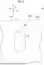
FIG. 1 is a perspective view of a packaging body of a first exemplary embodiment;
FIG. 2A is a perspective view of a second packaging material constituting the packaging body of the first exemplary embodiment, and FIG. 2B is a perspective view of a first packaging material;
FIG. 3 is an enlarged cross-sectional perspective view of the packaging body of the first exemplary embodiment;
FIG. 4 is an enlarged perspective view of a portion of the packaging body of the first exemplary embodiment, where a rail portion and a slit are provided;
FIG. 5 is an enlarged perspective view of a portion of the packaging body according to the first exemplary embodiment, where a handle member is provided;
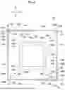
FIG. 6 is a plan view of the packaging body of the first exemplary embodiment;
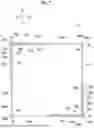
FIG. 7 is a plan view of a packaging body of a second exemplary embodiment;
FIG. 8 is an enlarged cross-sectional perspective view showing a first packaging material of the packaging body of the second exemplary embodiment in a partially cutout manner;
FIG. 9 is a cross-sectional perspective view showing the first packaging material and a second packaging material of the packaging body of the second exemplary embodiment in a partially cutout manner;
FIG. 10 is a cross-sectional perspective view of a lock mechanism of FIG. 8 in a locked state; and
FIG. 11 is an exploded perspective view of a packaging box using the packaging body of the first exemplary embodiment.
DETAILED DESCRIPTION
First Exemplary Embodiment
A packaging body of a first exemplary embodiment and a packaging box using the packaging body will be described.
Two directions perpendicular to a horizontal direction are defined as an X direction and a Y direction, and are indicated by an arrow X and an arrow Y, respectively. A vertical direction perpendicular to the X direction and the Y direction is defined as a Z direction and is indicated by an arrow Z. A view in the Z direction, that is, in the vertical direction is defined as plan view. In addition, the X direction or the Y direction may be referred to as a lateral direction.
Each drawing is shown only schematically. Dimensions, ratios, and the like of respective elements shown in the drawings may not necessarily match actual values. Even between a plurality of drawings, dimensions, ratios, numbers, and the like of respective elements may not necessarily match. Hatching representing a cross section may be omitted in a case where the view is difficult to see.
In addition, description of configurations and well-known configurations that are not directly related to the present invention may be omitted or simplified.
The same applies to a second exemplary embodiment described below.
Packaging Box
First, a packaging box of the present exemplary embodiment will be described.
As shown in FIG. 11, a packaging box 10 of the present exemplary embodiment is a rectangular parallelepiped or cubic corrugated cardboard box that packages a product 80 (see FIG. 6). The corrugated cardboard is a structure in which flat paper and corrugated paper are bonded with an adhesive. Cross sections in the drawings of the present exemplary embodiment are shown as a cross section of a board without distinguishing between flat paper and corrugated paper of corrugated cardboard.
The packaging box 10 of the present exemplary embodiment includes a bottom member 20, a lid member 30, and a packaging body 50 (see also FIGS. 1 and 6). The bottom member 20 includes a bottom plate portion 22 and a bottom side plate portion 24. Similarly, the lid member 30 includes a lid plate portion 32 and a lid side plate portion 34. The bottom plate portion 22 and the lid plate portion 32 have a rectangular shape in plan view. The bottom side plate portion 24 extends upward from each side portion of the bottom plate portion 22. The lid side plate portion 34 extends downward from each side portion of the lid plate portion 32.
The packaging body 50 is a tubular member having a rectangular shape in plan view. The bottom member 20 closes a lower opening portion 52 of the packaging body 50. In addition, the lid member 30 closes an upper opening portion 54 of the packaging body 50. Inner dimensions of the bottom member 20 and the lid member 30 are slightly larger than outer dimensions of the packaging body 50 in plan view. Therefore, the bottom side plate portion 24 and the lid side plate portion 34 are disposed outside the packaging body 50.
Packaging Body
Next, a packaging body of the present exemplary embodiment will be described.
As described above, the packaging body 50 shown in FIGS. 1 and 6 includes two first packaging materials 100A and 100B and two second packaging materials 200A and 200B (see also FIGS. 2A and 2B). Hereinafter, members constituting the first packaging material 100A will be denoted by reference numerals followed by A, and members constituting the first packaging material 100B will be denoted by reference numerals followed by B. Similarly, members constituting the second packaging material 200A will be denoted by reference numerals followed by A, and members constituting the second packaging material 200B will be denoted by reference numerals followed by B.
In addition, as shown in FIGS. 2A and 2B, the first packaging material 100A and the first packaging material 100B are identical members except that disposition positions are different from each other. Similarly, the second packaging material 200A and the second packaging material 200B are identical members except that disposition positions are different from each other. The same applies to members that make up each of the materials. Therefore, in a case where there is no need to distinguish between the two, A and B may be omitted.
As shown in FIGS. 1, 2A and 2B, and 6, the first packaging material 100 is a plate-like member having an L-shape in plan view in which a body side plate portion 110 and a body side plate portion 120 are connected at a corner portion 102 (see FIG. 2B). Similarly, the second packaging material 200 is a plate-like member having an L-shape in plan view in which a body side plate portion 210 and a body side plate portion 220 are connected at a corner portion 202 (see FIG. 2A). In the present exemplary embodiment, the body side plate portions 110A and 110B and the body side plate portions 210A and 210B are examples of a first piece. In addition, the body side plate portions 120A and 120B and the body side plate portions 220A and 220B are examples of a second piece.
As shown in FIGS. 1 and 6, the first packaging materials 100A and 100B are arranged such that the corner portions 102A and 102B are positioned at one pair of diagonal corners 51A and 51B of the packaging body 50 having a rectangular shape in plan view. The second packaging materials 200A and 200B are arranged such that the corner portions 202A and 202B are positioned at the other pair of diagonal corners 52A and 52B of the packaging body 50 having a rectangular shape in plan view. The body side plate portions 110A and 110B of the first packaging materials 100A and 100B are arranged along the X direction. Similarly, the body side plate portions 220A and 220B of the second packaging materials 200A and 200B are arranged along the X direction. In addition, the body side plate portions 120A and 120B of the first packaging materials 100A and 100B are arranged along the Y direction. Similarly, the body side plate portions 210A and 210B of the second packaging materials 200A and 200B are arranged along the Y direction.
As shown in FIGS. 1, 2B, and 6, the body side plate portions 110A, 110B, 120A, and 120B of the first packaging materials 100A and 100B have a double structure including inner plate portions 112A, 112B, 122A, and 122B and outer plate portions 114A, 114B, 124A, and 124B disposed outside the inner plate portions 112A, 112B, 122A, and 122B (see also FIG. 3). Gaps between the inner plate portions 112 and 122 and the outer plate portions 114 and 124 are referred to as gaps S1A, S1B, S2A, and S2B. In addition, widths of the gaps S1A, S1B, S2A, and S2B are the same. The inner plate portions 112A, 112B, 122A, and 122B are examples of an inner piece. In addition, the outer plate portions 114A, 114B, 124A, and 124B are examples of an outer piece.
As shown in FIG. 2B, the inner plate portions 112 and 122 and the outer plate portions 114 and 124 of the first packaging material 100 are joined by rail portions 131A, 131B, 132A, and 132B (see also FIG. 3). The rail portions 131 and 132 are strip-shaped members that are provided at intermediate portions of the gaps S1 and S2 in the vertical direction and that extend in the lateral direction. In the present exemplary embodiment, the rail portions 131A, 131B, 132A, and 132B are provided at two locations at intervals in the vertical direction. The rail portions 131A, 131B, 132A, and 132B on an upper side are provided at the same position in the vertical direction. Similarly, the rail portions 131A, 131B, 132A, and 132B on a lower side are provided at the same position in the vertical direction.
The rail portions 131A and 131B of the body side plate portions 110A and 110B of the first packaging materials 100A and 100B extend along the X direction. The rail portions 132A and 132B of the body side plate portions 120A and 120B of the first packaging materials 100A and 100B extend along the Y direction.
In addition, as shown in FIG. 4, a wide portion 133B is formed at an end part of the rail portion 131B. The wide portion 133B in the present exemplary embodiment is made wider in the up-down direction by the end part of the rail portion 131B protruding upward. Similarly, wide portions 133A, 134A, and 134B are formed at end parts of the other rail portions 131A, 132A, and 132B protruding upward (see FIG. 2B).
Here, the inner plate portions 112 and 122, the outer plate portions 114 and 124, and the rail portions 131 and 132 of the body side plate portions 110 and 120 of the first packaging material 100 of the present exemplary embodiment are made of corrugated cardboard. Therefore, the inner plate portions 112 and 122, the outer plate portions 114 and 124, and the rail portions 131 and 132 of the present exemplary embodiment are integrated by being joined to each other with an adhesive, a double-sided tape, or the like.
As shown in FIG. 2A, the body side plate portion 210 and the body side plate portion 220 of the second packaging material 200 are formed with slits 231A and 231B and slits 232A and 232B, respectively. In the present exemplary embodiment, the slits 231A, 231B, 232A, and 232B are provided at two locations at intervals in the vertical direction. The slits 231A and 231B of the body side plate portions 210A and 210B extend along the Y direction. The slits 232A and 232B of the body side plate portions 220A and 220B extend along the X direction. The slits 231A, 231B, 232A, and 232B are formed at the same heights as the rail portions 131 and 132 (see also FIGS. 1, 3, and 4).
Slit widths of the slits 231 and 232 in the vertical direction are slightly larger than widths of the wide portions 133 and 134 of the rail portions 131 and 132 in the vertical direction. In addition, stepped portions 233A, 233B, 234A, and 234B that are bent in a Z-shape downward are formed at opening-side end parts of the slits 231 and 232 (see also FIG. 4).
Lengths of the stepped portions 233 and 234 in the X direction or the Y direction are slightly larger than lengths of the wide portions 133 and 134 of the rail portions 131 and 132 in the X direction or the Y direction. In addition, widths of the stepped portions 233 and 234 in the Z direction are larger than widths of the wide portions 133 and 134 of the rail portions 131 and 132 in the Z direction (see also FIG. 4).
Portions extending from lower end parts of the stepped portions 233 and 234 of the slits 231 and 232 are referred to as opening-side slits 235A, 235B, 236A, and 236B. Slit widths of the opening-side slits 235A, 235B, 236A, and 236B in the vertical direction are also slightly larger than the widths of the wide portions 133 and 134 of the rail portions 131 and 132 in the vertical direction (see also FIG. 4).
As shown in FIGS. 1 and 6, a handle portion 90 is provided at an intermediate portion in the vertical direction of each of the corner portions 102A and 102B of the first packaging materials 100A and 100B (see also FIG. 5). Similarly, a handle portion 90 is provided at an intermediate portion in the vertical direction of each of the corner portions 202A and 202B of the second packaging materials 200A and 200B (see also FIG. 5). The handle portions 90 at the corner portions 102A, 102B, 202A, and 202B are provided at the same height.
The handle portion 90 of the present exemplary embodiment is a plate-like member created by folding one corrugated cardboard piece in an L-shape in plan view. In addition, in the present exemplary embodiment, the handle portion 90 made of corrugated cardboard is joined to the corner portions 102 and 202 with an adhesive, a double-sided tape, or the like.
As described above, the body side plate portions 110 and 120 of the first packaging material 100 shown in FIGS. 1 and 6 have a double structure including the inner plate portions 112 and 122 and the outer plate portions 114 and 124 (see also FIG. 2B and the like). The body side plate portions 210 and 220 of the second packaging material 200 are inserted into the gaps S1 and S2 between the inner plate portions 112 and 122 and the outer plate portions 114 and 124.
Specifically, the body side plate portion 210A of the second packaging material 200A is inserted into the gap S2B of the adjacent first packaging material 100B. The body side plate portion 220A is inserted into the gap S1A of the adjacent first packaging material 100A. Similarly, the body side plate portion 210B of the second packaging material 200B is inserted into the gap S2A of the adjacent first packaging material 100B. The body side plate portion 220B is inserted into the gap S1B of the adjacent first packaging material 100B.
In addition, the rail portions 131A, 131B, 132A, and 132B (see FIG. 2) of the first packaging material 100 are inserted into the slits 231A, 231B, 232A, and 232B (see FIGS. 2A and 2B) of the second packaging material 200 (see also FIGS. 3, 4, and 6).
Therefore, as shown in FIG. 6, the packaging body 50 is configured such that the body side plate portions 110 and 120 of the first packaging material 100 and the body side plate portions 210 and 220 of the second packaging material 200 are slidably connected in an approach and separation direction in which the corner portions 102 and 202 approach and separate from each other, the first packaging material 100 and the second packaging material 200 being adjacent to each other.
Specifically, the body side plate portion 110A of the first packaging material 100A and the body side plate portion 220A of the second packaging material 200A are slidably connected in the X direction in which the corner portion 102A and the corner portion 202A approach and separate from each other. Similarly, the body side plate portion 120A of the first packaging material 100A and the body side plate portion 210B of the second packaging material 200B are slidably connected in the Y direction in which the corner portion 102A and the corner portion 202B approach and separate from each other.
In addition, the body side plate portion 110B of the first packaging material 100B and the body side plate portion 220B of the second packaging material 200B are slidably connected in the X direction in which the corner portion 102B and the corner portion 202B approach and separate from each other. Similarly, the body side plate portion 120B of the first packaging material 100B and the body side plate portion 210A of the second packaging material 200A are slidably connected in the Y direction in which the corner portion 102B and the corner portion 202A approach and separate from each other.
In this way, the body side plate portions 110 and 120 of the first packaging material 100 and the body side plate portions 210 and 220 of the second packaging material 200 are slid in the approach and separation direction in which the corner portions 102 and 202 approach and separate from each other, the first packaging material 100 and the second packaging material 200 being adjacent to each other, thereby changing a size of the tubular packaging body 50 having a rectangular shape in plan view.
Operation
Next, an operation of the present exemplary embodiment will be described.
As shown in FIG. 6 and the like, the body side plate portions 110 and 120 of the first packaging material 100 and the body side plate portions 210 and 220 of the second packaging material 200 are slid in the approach and separation direction in which the corner portions 102 and 202 approach and separate from each other, the first packaging material 100 and the second packaging material 200 being adjacent to each other, thereby changing the size of the tubular packaging body 50 having a rectangular shape in plan view. Therefore, a size of the outer shape of the packaging body 50 in plan view may be changed. Therefore, the size of the tubular packaging body 50 having a rectangular shape in plan view can be adjusted to match a size of an outer shape of the product 80, which is an example of an object to be packaged, in plan view. In FIG. 6, the packaging body 50 indicated by a solid line is in the maximum state, and the packaging body 50 indicated by an imaginary line (two-dot chain line) is in the minimum state.
In addition, as an example of a method of using the packaging box 10 shown in FIG. 11, first, an operator places the product 80 on the bottom member 20. In addition, the operator adjusts the size of the packaging body 50 on a floor to match the size of the outer shape of the product 80 in plan view. Next, the operator holds the handle portion 90 (see also FIGS. 5 and 6) of the packaging body 50 and inserts the packaging body 50 over the product 80 from above. The operator finely adjusts the size of the packaging body 50 as necessary. Then, the operator covers the packaging body 50 with the lid member 30 and packages the packaging body 50.
As described above, a plurality of products 80 having different outer shapes can be packaged with one packaging body 50. In other words, by using the packaging body 50 of the present exemplary embodiment, it is not necessary to prepare a dedicated packaging body for each of the products 80 having different outer shapes.
Here, a case where a new product is delivered to a customer and an old product is collected from the customer will be described. In a case where the packaging body 50 of the present exemplary embodiment is not used, a new product is packaged with a dedicated packaging body and transported, and a dedicated packaging body for an old product is also transported together. Then, after the new product is delivered, the old product is packaged with the transported dedicated packaging body, collected, and transported. In addition, the packaging body in which the new product is packaged is also collected and transported together at the time of collection. Therefore, each of the dedicated packaging bodies for the old and new products is used only one way, and a production cost, a transportation cost, and a disposal cost are generated for each.
On the other hand, in a case where a new product is packaged with the packaging body 50 of the present exemplary embodiment, an old product to be collected can be packaged with the same packaging body 50 and collected. Therefore, there is no need to transport a dedicated packaging body for the old product to be collected together in a case of transporting the new product. In addition, there is no need to transport a dedicated packaging body for the new product together in a case of collecting the old product. Therefore, since the packaging body 50 is used reciprocally, a production cost, a transportation cost, and a disposal cost are reduced.
In addition, as shown in FIGS. 1 to 4 and the like, the body side plate portions 110 and 120 of the first packaging material 100 of the packaging body 50 of the present exemplary embodiment have a double structure including the inner plate portions 112 and 122 and the outer plate portions 114 and 124. The body side plate portions 210 and 220 of the second packaging material 200 are inserted into the gaps S1 and S2 between the inner plate portions 112 and 122 and the outer plate portions 114 and 124. Therefore, as compared with a case where the body side plate portions 110 and 120 of the first packaging material 100 have either the inner plate portions 112 and 122 or the outer plate portions 114 and 124, the first packaging material 100 and the second packaging material 200 are prevented from being unintentionally disengaged from each other.
In addition, in the packaging body 50 of the present exemplary embodiment, the rail portions 131 and 132 of the first packaging material 100 in the approach and separation direction are inserted into the slits 231 and 232 of the second packaging material 200 in the approach and separation direction. Therefore, as compared with a case where the rail portions 131 and 132 are not provided, the packaging body 50 is prevented from unintentionally coming out in the up-down direction in a case of changing the size of the outer shape of the packaging body 50 or from swinging up and down in a case of lifting the packaging body 50.
In addition, as shown in FIGS. 2A and 2B and 4, and the like, in the packaging body 50 of the present exemplary embodiment, the wide portions 133 and 134 are formed at the end parts of the rail portions 131 and 132. In addition, the stepped portions 233 and 234 that are bent in a Z-shape downward are formed at the opening-side end parts of the slits 231 and 232. Therefore, in a case where the outer shape of the packaging body 50 is increased, the wide portions 133 and 134 of the rail portions 131 and 132 come into contact with the stepped portions 233 and 234, thereby preventing the wide portions 133 and 134 from coming out. Therefore, as compared with a case where the width of the rail portion is constant, the second packaging material 200 is prevented from unintentionally coming out of the first packaging material 100. Therefore, for example, the time and effort required to reassemble the first packaging material 100 and the second packaging material 200 in a case where the second packaging material 200 unintentionally comes out of the first packaging material 100 is reduced. In a case of disassembling the first packaging material 100 and the second packaging material 200, the wide portions 133 and 134 of the rail portions 131 and 132 are moved below the stepped portions 233 and 234, so that the rail portions 131 and 132 come out of the opening-side slits 235 and 236.
In addition, as shown in FIGS. 1, 5, and 6, and the like, in the packaging body 50 of the present exemplary embodiment, the operator holds the handle portions 90 provided at the corner portions 102 and 202 and lifts the packaging body 50. Therefore, the packaging body 50 is easily lifted as compared with a case where the operator lifts the packaging body 50 by gripping the upper end part of the packaging body 50 with a hand.
In addition, the handle portion 90 of the packaging body 50 of the present exemplary embodiment is provided by joining a plate-like member created by folding one corrugated cardboard piece in an L-shape in plan view to the corner portions 102 and 202 with an adhesive, a double-sided tape, or the like. Therefore, the handle portion 90 is easily provided at the corner portions 102 and 202 as compared with a case where the handle portion is provided by forming the corner portion.
The bottom member 20 and the lid member 30 are prepared in a size that corresponds to the size of the outer shape of the product 80 to be packaged in plan view. In addition, the packaging body 50 is prepared in a size that corresponds to the height of the product 80 to be packaged.
Second Exemplary Embodiment
Next, a packaging body of the present exemplary embodiment will be described. In addition, the members identical to the members in the first exemplary embodiment are denoted by the identical reference numerals, and duplicate description will be omitted or simplified.
As shown in FIG. 7, a packaging body 53 of the second exemplary embodiment is a tubular member having a rectangular shape in plan view, the packaging body 53 including two first packaging materials 300A and 300B and two second packaging materials 400A and 400B.
The first packaging materials 300A and 300B of the packaging body 53 are members corresponding to the first packaging materials 100A and 100B of the first exemplary embodiment, and the second packaging materials 400A and 400B are members corresponding to the second packaging materials 200A and 200B of the first exemplary embodiment (see FIGS. 1 and 6, and the like). In addition, as in the above-described exemplary embodiment, the first packaging material 300A and the first packaging material 300B are identical members except that disposition positions are different from each other. Similarly, the second packaging material 400A and the second packaging material 400B are identical members except that disposition positions are different from each other. The same applies to members that make up each of the materials. Therefore, in a case where there is no need to distinguish between the two, A and B may be omitted.
In addition, as with the packaging body 50 of the first exemplary embodiment, the packaging body 53 becomes a packaging box with the bottom member 20 closing the lower opening portion of the packaging body 53 and the lid member 30 closing the upper opening portion of the packaging body 50 (see FIG. 11).
The first packaging material 300 is a member having an L-shape in plan view in which a body side plate portion 310 and a body side plate portion 320 are connected at a corner portion 302. Similarly, the second packaging material 400 is a member having an L-shape in plan view in which a body side plate portion 410 and a body side plate portion 420 are connected at a corner portion 402. The first packaging materials 300A and 300B are arranged such that the corner portions 302A and 302B are positioned at one pair of diagonal corners 54A and 54B of the packaging body 53 having a rectangular shape in plan view. The second packaging materials 400A and 400B are arranged such that the corner portions 402A and 402B are positioned at the other pair of diagonal corners 55A and 55B of the packaging body 53 having a rectangular shape in plan view.
The body side plate portions 310A and 310B and the body side plate portions 410A and 410B are examples of a first piece. In addition, the body side plate portions 320A and 320B and the body side plate portions 420A and 420B are examples of a second piece. The body side plate portions 310 and 320 of the first packaging material 300 have a double structure of inner plate portions 112 and 122 and outer plate portions 114 and 124.
As shown in FIGS. 8 and 9, the inner plate portions 112 and 122 and the outer plate portions 114 and 124 are connected by a rail portion 330. The rail portion 330 is a member that is provided at an intermediate portion of each of gaps S1A, S1B, S2A, and S2B in the vertical direction and that extends in the lateral direction. The rail portions 330 are provided at two locations at intervals in the vertical direction (see FIG. 9). The rail portion 330 includes a first L-shaped member 331 and a second L-shaped member 332 that extend in the lateral direction and that have an L-shaped cross section.
The first L-shaped member 331 is composed of a first horizontal portion 333 and a first vertical portion 335. One end part of the first horizontal portion 333 is joined to the inner plate portions 112 and 122 with an adhesive, a double-sided tape, or the like. The first vertical portion 335 extends upward from the other end part of the first horizontal portion 333. The first vertical portion 335 is not joined to the outer plate portions 114 and 124.
Similarly, the second L-shaped member 332 is composed of a second horizontal portion 334 and a second vertical portion 336. One end part of the second horizontal portion 334 is joined to the outer plate portions 214 and 224 with an adhesive, a double-sided tape, or the like. The second vertical portion 336 extends downward from the other end part of the second horizontal portion 334. The second vertical portion 336 is not joined to the inner plate portions 112 and 122.
The second vertical portion 336 of the second L-shaped member 332 is inserted between the first vertical portion 335 of the first L-shaped member 331 and the inner plate portions 112 and 122. From another perspective, the first vertical portion 335 of the first L-shaped member 331 is inserted between the second vertical portion 336 of the second L-shaped member 332 and the outer plate portions 114 and 124.
Therefore, in the packaging material 300, the inner plate portions 112 and 122 and the outer plate portions 114 and 124 in the body side plate portions 310 and 320 are connected such that the outer plate portions 114 and 124 are movable in the up-down direction relative to the inner plate portions 112 and 122.
As shown in FIG. 9, each of the body side plate portions 410 and 420 of the second packaging material 400 is formed with a slit 430. The slits 430 are provided at two locations at intervals in the vertical direction. The slit 430 is formed at the same height as the rail portion 330.
The rail portion 330 of the first packaging material 300 is inserted into the slit 430 of the second packaging material 400. Therefore, the packaging body 53 is configured such that the body side plate portions 310 and 320 of the first packaging material 300 and the body side plate portions 410 and 420 of the second packaging material 400 are slidably connected in an approach and separation direction in which the corner portions 302 and 402 approach and separate from each other, the first packaging material 300 and the second packaging material 400 being adjacent to each other.
As shown in FIG. 8, the packaging body 53 is provided with a lock mechanism 450 that locks sliding of the second packaging material 400 with respect to the first packaging material 300 in a case where the outer plate portions 114 and 124 move upward relative to the inner plate portions 112 and 122 in the first packaging material 300.
The lock mechanism 450 includes an upper serrated portion 340 and a lower serrated portion 440 provided in the gaps S1A, S1B, S2A, and S2B. The upper serrated portion 340 extending in the lateral direction is joined to an upper edge portion 119 of the inner plate portions 112 and 122. The upper serrated portion 340 is configured by arranging inverted triangular teeth 342 protruding downward.
As shown in FIG. 9, a lower serrated portion 440 is formed on an upper edge portion 419 of the body side plate portions 410 and 420 of the second packaging material 400. The lower serrated portion 440 is configured by arranging triangular teeth 442 protruding upward.
As shown in FIG. 10, in a case where the outer plate portions 114 and 124 move upward relative to the inner plate portions 112 and 122 in the first packaging material 300, the second horizontal portion 334 of the second L-shaped member 332 comes into contact with an upper surface of an inner wall of the slit 430 of the second packaging material 400. As a result, the second packaging material 400 also moves upward. In a case where the second packaging material 400 moves upward, the lower serrated portion 440 of the second packaging material 400 engages and locks with the upper serrated portion 340 of the inner plate portions 112 and 122 of the first packaging material 300.
Operation
Next, an operation of the present exemplary embodiment will be described.
As shown in FIG. 7 and the like, the body side plate portions 310 and 320 of the first packaging material 300 and the body side plate portions 410 and 420 of the second packaging material 400 are slid in the approach and separation direction in which the corner portions 302 and 402 approach and separate from each other, the first packaging material 300 and the second packaging material 400 being adjacent to each other, thereby changing the size of the tubular packaging body 53 having a rectangular shape in plan view. Therefore, a size of the outer shape of the packaging body 53 in plan view may be changed. Therefore, the size of the tubular packaging body 53 having a rectangular shape in plan view can be adjusted to match the size of the outer shape of the product 80 (see FIG. 6) in plan view.
As in the first exemplary embodiment, as an example of a method of using the packaging body 53, the operator places the product 80 (see FIG. 6) on the bottom member 20 (see FIG. 11). In addition, the operator adjusts the size of the packaging body 53 on a floor to match the size of the outer shape of the product 80 in plan view. Next, the operator holds the handle portion 90 (see FIG. 5) of the packaging body 53 and inserts the packaging body 53 over the product 80 from above. The operator finely adjusts the size of the packaging body 53 as necessary. Then, the operator covers the packaging body 53 with the lid member 30 (see FIG. 11) and packages the packaging body 53.
As shown in FIGS. 8 to 10, in the rail portion 330 of the packaging body 53 of the present exemplary embodiment, the second vertical portion 336 of the second L-shaped member 332 is inserted between the first vertical portion 335 of the first L-shaped member 331 and the inner plate portions 112 and 122. Therefore, the rail portion 330 connects the inner plate portions 112 and 122 and the outer plate portions 114 and 124 in the body side plate portions 310 and 320 of the first packaging material 300 are connected such that the outer plate portions 114 and 124 are movable in the up-down direction relative to the inner plate portions 112 and 122.
As shown in FIG. 10, in a case where the outer plate portions 114 and 124 move upward relative to the inner plate portions 112 and 122, the second packaging material 400 also moves upward. In a case where the second packaging material 400 moves upward, the lower serrated portion 440 of the second packaging material 400 engages and locks with the upper serrated portion 340 of the inner plate portions 112 and 122 of the first packaging material 300. Then, the inner plate portions 112 and 122 also move upward in a locked state.
As shown in FIG. 9, in a case where the packaging body 53 of the present exemplary embodiment is placed on a floor or the like, the lower serrated portion 440 of the outer plate portions 114 and 124 and the upper serrated portion 340 of the inner plate portions 112 and 122 in the body side plate portions 310 and 320 of the first packaging material 300 are separated and do not engage. Therefore, the size of the packaging body 53 can be changed by sliding in the approach and separation direction in which the corner portions 302 and 402 of the packaging body 53 approach and separate from each other.
However, as shown in FIG. 10, in a case where the operator lifts the packaging body 53 by holding the corner portion 302 (see FIG. 7 and the like) of the outer plate portions 114 and 124 in the body side plate portions 310 and 320 of the first packaging material 300, the outer plate portions 114 and 124 move upward relative to the inner plate portions 112 and 122. As a result, the lower serrated portion 440 of the second packaging material 400 engages and locks with the upper serrated portion 340 of the inner plate portions 112 and 122. Therefore, sliding does not occur in the approach and separation direction in which the corner portions 302 and 402 of the packaging body 53 approach and separate from each other (see FIG. 6). That is, through the locking, the size of the packaging body 53 is prevented from being unintentionally changed. Therefore, for example, in a case where the size of the packaging body 53 is adjusted to match the size of the outer shape of the product 80 (see FIG. 6) in plan view, and the packaging body 53 is inserted over the product 80 from above by holding the handle portion 90 (see FIG. 5) of the packaging body 53, the size of the packaging body 53 is prevented from being unintentionally changed.
As described above, as compared to a case where the lock mechanism 450 is not provided, unintentional sliding in a case where the packaging body 53 is lifted is prevented.
In addition, the upper serrated portion 340 and the lower serrated portion 440 of the lock mechanism 450 are provided in the gaps S1A, S1B, S2A, and S2B. Therefore, the lock mechanism is less visible from outside the packaging body 53 as compared with a case where the lock mechanism is provided outside the gaps S1A, S1B, S2A, and S2B.
As in the first exemplary embodiment, the bottom member 20 and the lid member 30 are prepared in a size that corresponds to the size of the outer shape of the product 80 to be packaged in plan view. In addition, the packaging body 50 is prepared in a size that corresponds to the height of the product 80 to be packaged.
Others
The present invention is not limited to the exemplary embodiments.
For example, the packaging bodies 50 and 53 of the above-described exemplary embodiments are made of corrugated cardboard, but the present invention is not limited to this. A part or an entirety of the packaging box may be made of materials other than corrugated cardboard, for example, paper materials other than corrugated cardboard, wood, resin, and metal.
Further, the present invention can be implemented in various ways without departing from the concept of the present invention. A plurality of exemplary embodiments can be implemented in combination as appropriate.
Supplementary Note
-
- (((1)))
A packaging body comprising:
-
- four packaging materials arranged in a rectangular shape in plan view with respective corner portions as four corners, each of the four packaging materials having a first piece and a second piece connected at a corner portion in an L-shape in plan view,
- wherein the first piece and the second piece of the packaging materials adjacent to each other are slidably connected in an approach and separation direction in which the corner portions approach and separate from each other.
- (((2)))
The packaging body according to (((1))),
-
- wherein the packaging materials include
- two first packaging materials whose corner portions are arranged diagonally on one side, and
- two second packaging materials whose corner portions are arranged diagonally on the other side,
- a first piece and a second piece of a first packaging material have a double structure including an inner piece and an outer piece arranged outside the inner piece with a gap therebetween, and
- a second packaging material has a first piece inserted into a gap of one of adjacent first packaging materials and a second piece inserted into a gap of the other adjacent first packaging material.
- (((3)))
- wherein the packaging materials include
The packaging body according to (((2))),
-
- wherein the inner piece and the outer piece of the first packaging material are connected by a rail portion that is provided in the gap and that extends along the approach and separation direction, and
- the first piece and the second piece of the second packaging material are formed with a slit that extends along the approach and separation direction and into which the rail portion is inserted.
- (((4)))
The packaging body according to (((3))),
-
- wherein a wide portion is formed at an end part of the rail portion of the first packaging material, and
- a step against which the wide portion abuts is formed at an opening-side end part of the slit of the second packaging material.
- (((5)))
The packaging body according to (((3))),
-
- wherein the rail portion of the first packaging material connects the inner piece and the outer piece such that the outer piece is movable in an up-down direction relative to the inner piece, and
- the packaging body includes a lock mechanism that locks sliding of the second packaging material with respect to the first packaging material in a case where the outer piece moves upward relative to the inner piece.
- (((6)))
The packaging body according to (((5))),
-
- wherein the lock mechanism is provided in the gap, and
- in a case where the outer piece moves upward relative to the inner piece, a lower-protruding upper serrated portion provided on an upper edge portion of the inner piece of the first packaging material engages and locks with an upper-protruding lower serrated portion provided on an upper edge portion of the second packaging material.
- (((7)))
The packaging body according to any one of (((1))) to (((6))),
-
- wherein a handle portion is provided at an intermediate portion in an up-down direction of each of the corner portions of the four packaging materials.
- (((8)))
The packaging body according to (((7))),
-
- wherein the handle portion is configured such that a plate-like member having an L-shape in plan view is joined to the corner portion.
- (((9)))
A packaging box comprising:
-
- the packaging body according to any one of (((1))) to (((8)));
- a bottom member that closes a lower opening portion of the packaging body; and
- a lid member that closes an upper opening portion of the packaging body.
- (((10)))
A packaging box comprising:
-
- the packaging body according to any one of (((1))) to (((8)));
- a bottom member that closes a lower opening portion of the packaging body; and
- a lid member that closes an upper opening portion of the packaging body,
- wherein a dimension of the packaging body is adjusted to match an outer shape of an object to be packaged.
The foregoing description of the exemplary embodiments of the present invention has been provided for the purposes of illustration and description. It is not intended to be exhaustive or to limit the invention to the precise forms disclosed. Obviously, many modifications and variations will be apparent to practitioners skilled in the art. The embodiments were chosen and described in order to best explain the principles of the invention and its practical applications, thereby enabling others skilled in the art to understand the invention for various embodiments and with the various modifications as are suited to the particular use contemplated. It is intended that the scope of the invention be defined by the following claims and their equivalents.
Claims
What is claimed is:1. A packaging body comprising:
four packaging materials arranged in a rectangular shape in plan view with respective corner portions as four corners, each of the four packaging materials having a first piece and a second piece connected at a corner portion in an L-shape in plan view,
wherein the first piece and the second piece of the packaging materials adjacent to each other are slidably connected in an approach and separation direction in which the corner portions approach and separate from each other.
2. The packaging body according to claim 1,
wherein the packaging materials include
two first packaging materials whose corner portions are arranged diagonally on one side, and
two second packaging materials whose corner portions are arranged diagonally on the other side,
a first piece and a second piece of a first packaging material have a double structure including an inner piece and an outer piece arranged outside the inner piece with a gap therebetween, and
a second packaging material has a first piece inserted into a gap of one of adjacent first packaging materials and a second piece inserted into a gap of the other adjacent first packaging material.
3. The packaging body according to claim 2,
wherein the inner piece and the outer piece of the first packaging material are connected by a rail portion that is provided in the gap and that extends along the approach and separation direction, and
the first piece and the second piece of the second packaging material are formed with a slit that extends along the approach and separation direction and into which the rail portion is inserted.
4. The packaging body according to claim 3,
wherein a wide portion is formed at an end part of the rail portion of the first packaging material, and
a step against which the wide portion abuts is formed at an opening-side end part of the slit of the second packaging material.
5. The packaging body according to claim 3,
wherein the rail portion of the first packaging material connects the inner piece and the outer piece such that the outer piece is movable in an up-down direction relative to the inner piece, and
the packaging body includes a lock mechanism that locks sliding of the second packaging material with respect to the first packaging material in a case where the outer piece moves upward relative to the inner piece.
6. The packaging body according to claim 5,
wherein the lock mechanism is provided in the gap, and
in a case where the outer piece moves upward relative to the inner piece, a lower-protruding upper serrated portion provided on an upper edge portion of the inner piece of the first packaging material engages and locks with an upper-protruding lower serrated portion provided on an upper edge portion of the second packaging material.
7. The packaging body according to claim 1,
wherein a handle portion is provided at an intermediate portion in an up-down direction of each of the corner portions of the four packaging materials.
8. The packaging body according to claim 7,
wherein the handle portion is configured such that a plate-like member having an L-shape in plan view is joined to the corner portion.
9. A packaging box comprising:
the packaging body according to claim 1;
a bottom member that closes a lower opening portion of the packaging body; and
a lid member that closes an upper opening portion of the packaging body.
10. A packaging box comprising:
the packaging body according to claim 2;
a bottom member that closes a lower opening portion of the packaging body; and
a lid member that closes an upper opening portion of the packaging body.
11. A packaging box comprising:
the packaging body according to claim 3;
a bottom member that closes a lower opening portion of the packaging body; and
a lid member that closes an upper opening portion of the packaging body.
12. A packaging box comprising:
the packaging body according to claim 4;
a bottom member that closes a lower opening portion of the packaging body; and
a lid member that closes an upper opening portion of the packaging body.
13. A packaging box comprising:
the packaging body according to claim 5;
a bottom member that closes a lower opening portion of the packaging body; and
a lid member that closes an upper opening portion of the packaging body.
14. A packaging box comprising:
the packaging body according to claim 6;
a bottom member that closes a lower opening portion of the packaging body; and
a lid member that closes an upper opening portion of the packaging body.
15. A packaging box comprising:
the packaging body according to claim 7;
a bottom member that closes a lower opening portion of the packaging body; and
a lid member that closes an upper opening portion of the packaging body.
16. A packaging box comprising:
the packaging body according to claim 8;
a bottom member that closes a lower opening portion of the packaging body; and
a lid member that closes an upper opening portion of the packaging body.
17. A packaging box comprising:
the packaging body according to claim 1;
a bottom member that closes a lower opening portion of the packaging body; and
a lid member that closes an upper opening portion of the packaging body,
wherein a dimension of the packaging body is adjusted to match an outer shape of an object to be packaged.
18. A packaging box comprising:
the packaging body according to claim 2;
a bottom member that closes a lower opening portion of the packaging body; and
a lid member that closes an upper opening portion of the packaging body,
wherein a dimension of the packaging body is adjusted to match an outer shape of an object to be packaged.
19. A packaging box comprising:
the packaging body according to claim 3;
a bottom member that closes a lower opening portion of the packaging body; and
a lid member that closes an upper opening portion of the packaging body,
wherein a dimension of the packaging body is adjusted to match an outer shape of an object to be packaged.
20. A packaging box comprising:
the packaging body according to claim 4;
a bottom member that closes a lower opening portion of the packaging body; and
a lid member that closes an upper opening portion of the packaging body,
wherein a dimension of the packaging body is adjusted to match an outer shape of an object to be packaged.
Images & Drawings included:


Sources:
- United States Patent and Trademark Office - verify current appl. status at the USPTO↗
Similar patent applications:
- » 20230303288
PACKAGING BOX BODY, INFORMATION PROCESSING APPARATUS, AND PROGRAM - » 20160251134
Animal litter box package body - » 20200216250
METHOD FOR PACKAGING DISPLAY PANELS, DISPLAY PANEL PACKAGING BOX, AND PACKAGING BOX BODY - » 20080202068
PACKAGING OBJECT SUPPLYING APPARATUS, BOX BODY SUPPLYING APPARATUS, BOXING APPARATUS, PACKAGING SYSTEM AND PACKAGING METHOD - » 10434467
Packaging object supplying apparatus, box body supplying apparatus, boxing apparatus, packaging system and packaging method - » 20210315273
INTEGRATED STRUCTURE OF ELECTRONIC ATOMIZER BODY AND PACKAGE BOX - » 20190161233
PACKAGING ASSEMBLY WITH PRODUCT CONTAINER BOX BODY AND INFLATABLE HEAD COMPONENT
Recent applications in this class:
- » 20240351736 2024-10-24
PACKAGING BOX AND CARDBOARD STRUCTURE - » 20220127038 2022-04-28
MODULAR PACKAGING SYSTEM - » 20190023445 2019-01-24
Portable display containers and methods of making and using the same - » 20180186503 2018-07-05
Paperboard carton - » 20170334596 2017-11-23
Portable display containers and methods of making and using the same - » 20160159515 2016-06-09
Flat foldable packaging - » 20150298850 2015-10-22
Portable display containers and methods of making and using the same - » 20150217897 2015-08-06
Carton with opening feature - » 20150175293 2015-06-25
BOX MADE OF A CARDBOARD SHEET MATERIAL, BLANK OR BLANK ASSEMBLY, AND METHOD AND DEVICE FOR FORMING SUCH A BOX - » 20140353365 2014-12-04
PACKING UNIT
Recent applications for this Assignee:
- » 20260082008 2026-03-19
INFORMATION PROCESSING SYSTEM, NON-TRANSITORY COMPUTER READABLE MEDIUM, AND IMAGE FORMING SYSTEM - » 20260082005 2026-03-19
BINDING PROCESSING DEVICE - » 20260080528 2026-03-19
INFORMATION PROCESSING SYSTEM AND NON-TRANSITORY COMPUTER READABLE MEDIUM - » 20260079439 2026-03-19
IMAGE FORMING APPARATUS - » 20260079437 2026-03-19
SHEET DISCHARGE AND ACCOMMODATION DEVICE AND IMAGE FORMING APPARATUS - » 20260079435 2026-03-19
MEDIUM PROCESSING APPARATUS AND IMAGE FORMING APPARATUS - » 20260079415 2026-03-19
ELECTROSTATIC CHARGE IMAGE DEVELOPING TONER, ELECTROSTATIC CHARGE IMAGE DEVELOPER, TONER CARTRIDGE, PROCESS CARTRIDGE, IMAGE FORMING APPARATUS, AND IMAGE FORMING METHOD - » 20260079413 2026-03-19
ELECTROPHOTOGRAPHIC PHOTORECEPTOR, PROCESS CARTRIDGE, AND IMAGE FORMING APPARATUS - » 20260077976 2026-03-19
POST-PROCESSING DEVICE AND IMAGE FORMING APPARATUS - » 20260077971 2026-03-19
FEEDING DEVICE