TOOL CONTROL SYSTEM FOR WORK VEHICLE
US20260085488A1
2026-03-26
19/333,212
2025-09-18
Smart Summary: A work vehicle has a main body, a boom that can move up and down, an arm that connects to the boom, and a tool attached to the arm. The tool control system helps manage how the boom and arm move by using special cylinders that can extend and retract. Operators can input their commands using a device that responds to their movements. A diverter connects the boom and arm cylinders, allowing fluid to flow between them, which helps control their movement. The system includes a controller that adjusts the flow of fluid to ensure the boom and arm work together smoothly. 🚀 TL;DR
Abstract:
A work vehicle includes a main body, a boom pivotably connected to the main body, an arm pivotably connected to the boom, and a tool connected to the arm. A tool control system for the work vehicle includes a boom cylinder to extend and retract the boom, an arm cylinder to extend and retract the arm, at least one input device usable to input intentions of an operator based on manipulation directions, a diverter connecting the boom and arm cylinders, and a controller. The diverter can carry working fluid exiting the boom cylinder into the arm cylinder. The diverter includes a diverter passage, and a diverter valve disposed in the diverter passage to control an amount of the working fluid flowing through the diverter passage. The controller controls the boom and arm cylinders, and the diverter valve to control the amount of the working fluid flowing through the diverter passage.
Inventors:
- Kendrick Michael GIBSON 5 🇺🇸 Chattanooga, TN, United States
- Patrick Earl ANDERSON 1 🇺🇸 Shawano, WI, United States
- Jeffrey Bertrand HUNTINGTON 1 🇺🇸 Shawano, WI, United States
Applicant:
Interested in similar patents?
Get notified when new applications in this technology area are published.
Classification:
E02F3/435 » CPC main
Dredgers; Soil-shifting machines mechanically-driven with digging tools mounted on a dipper- or bucket-arm, i.e. there is either one arm or a pair of arms , e.g. dippers, buckets; Component parts; Drives for dippers, buckets, dipper-arms or bucket-arms; Control of dipper or bucket position; Control of sequence of drive operations for dipper-arms, backhoes or the like
E02F9/2203 » CPC further
Component parts of dredgers or soil-shifting machines, not restricted to one of the kinds covered by groups - ; Drives; Control devices; Hydraulic or pneumatic drives Arrangements for controlling the attitude of actuators, e.g. speed, floating function
E02F9/2267 » CPC further
Component parts of dredgers or soil-shifting machines, not restricted to one of the kinds covered by groups - ; Drives; Control devices; Hydraulic or pneumatic drives; Arrangements or adaptations of elements for hydraulic drives Valves or distributors
E02F3/43 IPC
Dredgers; Soil-shifting machines mechanically-driven with digging tools mounted on a dipper- or bucket-arm, i.e. there is either one arm or a pair of arms , e.g. dippers, buckets; Component parts; Drives for dippers, buckets, dipper-arms or bucket-arms Control of dipper or bucket position; Control of sequence of drive operations
E02F9/22 IPC
Component parts of dredgers or soil-shifting machines, not restricted to one of the kinds covered by groups - ; Drives; Control devices Hydraulic or pneumatic drives
Description
CROSS REFERENCE TO RELATED APPLICATIONS
This application claims the benefit under 35 U.S.C. § 119(e) of U.S. Provisional Application No. 63/696,929, filed Sep. 20, 2024. The entire disclosure of U.S. Provisional Application No. 63/696,929 is hereby incorporated herein by reference.
BACKGROUND
Field of the Invention
The present disclosure generally relates to a tool control system for a work vehicle. More specifically, the present disclosure relates to a tool control system for a work vehicle, which facilitates efficiently extending a tool controlled by an operator.
Background Information
Work vehicles are used in construction, farming, forestry, etc. Whether used in construction, farming, forestry, etc., work vehicles typically have one or more work implements or tools attached thereto to perform some work. On such a work vehicle, at least one work implement is coupled to the vehicle body and/or chassis. Regardless of the work implement, a work vehicle includes a ground propulsion apparatus that uses tracks or wheels to propel and/or steer the forestry machine. The tracks or wheels also serve to support the main body of the work vehicle. One example of a work vehicle is a forestry work vehicle that is used for logging (e.g., cutting trees and/or transporting felled trees) or various other forestry purposes. One example of a forestry machine is a feller buncher or harvester. On a harvester, the work implement typically includes a feller head with a spinning disc saw used to fell trees. Another possible forestry work implement is a clamp used to pick up and load felled trees.
In the case of a feller buncher or harvester, the feller head is pivotally mounted at the end of an arm. The arm is pivotally mounted to a boom. The boom is pivotally mounted to the vehicle body or chassis. A hydraulic circuit is connected to a boom cylinder, an arm cylinder and a feller head cylinder to control movement of the feller head. The hydraulic circuit is also connected to the saw blade to rotate the saw blade. An operator controls the movement and operation of the feller head by controlling the hydraulics using multiple operating members such as joysticks as well as other controls such as foot pedals and dash buttons/switches.
Some examples of work vehicles are disclosed in U.S. Pat. No. 11,959,252, Japanese Patent No. 2583148B2, U.S. Pat. No. 9,249,556, Japanese Patent No. JP1988022198Y2, Japanese Patent No. JP1989043161B2, U.S. Pat. No. 10,519,628, and European Patent No. 4039892A4.
SUMMARY
The boom and arm of the work equipment on a feller buncher move together to move the cutting tool away from the machine toward a tree. For this to be accomplished, hydraulic oil is sent from a pump through valving to retract the boom cylinder and extend the arm cylinder, which are attached to the boom and arm of the work equipment, respectively.
It has been discovered that if hydraulic fluid (or hydraulic oil) can be repurposed from the base of the boom cylinder to the base of the am cylinder, then pump flow can be conserved. This conservation of pump flow means the engine will not be required to produce as much power, which in turn saves fuel.
Therefore, one object of this invention is to repurpose/redirect hydraulic fluid in order to save the customer (operator) money by reducing the amount of fuel consumed by the engine.
Another object is an alternative version in which the customer can save more money by having a higher production machine, e.g., by diverting an even larger amount of hydraulic fluid (oil).
It has also been discovered that it may not always be desired to divert hydraulic fluid, e.g., sometimes during extension or always during retraction/
Therefore, another object of this invention is to be capable of closing off or stopping the repurpose/redirection of hydraulic fluid.
In view of the state of the known technology and in accordance with a first aspect of the present disclosure, a tool control system for a work vehicle is provided. The work vehicle includes a main body, a boom pivotably connected to the main body, an arm pivotably connected to the boom, and a tool connected to the arm. A tool control system for the work vehicle includes a boom cylinder configured to extend the boom from the main body and retract the boom to the main body, an arm cylinder configured to extend the arm from the boom and retract the arm to the boom, at least one input device usable to input intentions of an operator based on manipulation directions of at least one input device, a diverter connecting the boom cylinder and arm cylinder, and a controller. The diverter is configured to carry working fluid exiting the boom cylinder into the arm cylinder. The diverter includes a diverter passage, and a diverter valve disposed in the diverter passage to control an amount of the working fluid flowing through the diverter passage. The controller is configured to control the boom cylinder and the arm cylinder in response to the manipulation directions of the at least one input device, and the diverter valve to control the amount of the working fluid flowing through the diverter passage.
In accordance with second to twelfth aspects of the present disclosure, the tool control system of the first aspect may further include the feature(s) of any one or more of those recited in the second to twelfth claims filed herewith.
In accordance with another aspect of the present disclosure, a work vehicle can be provided that may include the tool control system according to any one or more of the preceding aspects.
It will be apparent to those having ordinary skill in the art from this disclosure that the above aspect are merely examples of illustrative embodiment(s) of this invention and do not limit the scope of this invention.
Also, other objects, features, aspects and advantages of the disclosed work vehicle will become apparent to those skilled in the work vehicle field from the following detailed description, which, taken in conjunction with the annexed drawings, discloses exemplary embodiments of the work vehicle.
BRIEF DESCRIPTION OF THE DRAWINGS
Referring now to the attached drawings which form a part of this original disclosure:
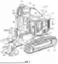
FIG. 1 is a front-left side perspective view of a work vehicle including a tool control system in accordance with an embodiment;
FIG. 2 is a left side elevational view of a work vehicle in accordance with another embodiment;
FIG. 3 is a front elevational view of the work vehicle illustrated in FIG. 2;
FIG. 4 is an operator view of a first (right or left) control lever of the work vehicle, with buttons (first or second user inputs) to show an example button program layout;
FIG. 5 is an operator view of a second (left or right) control joystick of the work vehicle, with buttons (second or first user inputs) to show an example button program layout;
FIG. 6 is an enlarged elevation view of a dash panel of a dashboard of the work vehicle, with a diverter valve control switch and other programmable switches (buttons);
FIG. 7 is a simplified schematic illustration of a machine controller and other control components of the work vehicle;
FIG. 8 is a diagrammatic view of the work vehicle, illustrating an extending work equipment operation with the diverter valve in a closed position;
FIG. 9 is a diagrammatic view of the work vehicle, illustrating a retracting work equipment operation with the diverter valve in the closed position;
FIG. 10 a diagrammatic view of the tool control system of the work vehicle, illustrating an extending work equipment operation with the diverter valve in a closed position (normal operation);
FIG. 11 is a diagrammatic view of the tool control system of the work vehicle, illustrating an extending work equipment operation with the diverter valve in an open position and pump flow reduced (eco operation mode);
FIG. 12 is a diagrammatic view of the tool control system of the work vehicle, illustrating an extending work equipment operation with the diverter valve in an open position and pump flow not reduced (performance operation mode); and
FIG. 13 is flow chart illustrating the control logic of the tool control system during the extending work equipment operations illustrated in FIGS. 10-12.
DETAILED DESCRIPTION OF THE EMBODIMENT(S)
Selected embodiments will now be explained with reference to the drawings. It will be apparent to those skilled in the art from this disclosure that the following description of the embodiments is provided for illustration only and not for the purpose of limiting the invention as defined by the appended claims and their equivalents.
Referring initially to FIGS. 1-3 and 8-12, a work vehicle 10 is respectively illustrated. As explained below, the work vehicle 10 has improved operation of a work implement 18 mounted thereto. Specifically, the work vehicle 10 includes a tool control system 40 with a diverter 80 (illustrated in FIGS. 8-12), which can divert hydraulic fluid for more efficient operation, in accordance with this disclosure. In the illustrated embodiment(s), the work vehicle 10 is a tree harvester, such as a short tail tracked harvester. While it will be apparent to those skilled in the art from this disclosure that certain aspects may be particularly beneficial in the illustrated tree harvester, it will also be apparent that many of the aspects of the work vehicle 10 can be applied to other types of forestry machines. For example, the present disclosure may be applicable to wheeled forestry machines, long tailed tree harvesters, or any other forestry machine in which it is desired for a work implement to be easily operated by the operator. Moreover, it will be apparent that many of the aspects of the work machine 10 can be applied to other types of work machines (e.g., construction and/or farming) in which it is desired for a work implement to be easily and efficiently operated by the operator.
In the illustrated embodiments, the work machine 10 includes a ground propulsion apparatus 12, a chassis 14, a vehicle body 16, and the work implement 18. The operator controls the control system 40 to control the work implement 18, as explained in more detail below.
In the illustrated embodiments, the ground propulsion apparatus 12 has a pair of tracks 12L and 12R used to propel and maneuver the work vehicle 10 in a conventional manner. However, it will be apparent to those skilled in the work vehicle field from this disclosure that the present disclosure is also applicable the wheeled work vehicles in which the tracks are replaced by wheels or some other means of moving the work vehicle 10 along the ground. The ground propulsion apparatus 12 supports the chassis 14, which supports the vehicle body 16. The vehicle body 16 is pivotally supported by and attached to the ground propulsion apparatus 12 via the chassis 14. The work implement 18 is movably attached to the vehicle body 16. The vehicle body 16 includes a deck 20 on which an operator cab 22 is disposed and from which an operator can operate the work vehicle 10.
The ground propulsion apparatus 12 of the illustrated embodiments includes an undercarriage and other conventional parts that enable the work vehicle 10 to move along a ground surface. In the illustrated embodiments, the ground propulsion apparatus 12 includes the left or first track 12L and the right or second track 12R. The first and second tracks 12L and 12R are arranged to contact the ground surface. The first and second tracks 12L and 12R are driven by, for example, a hydraulic motor/pump (shown only in FIGS. 10-12). In the illustrated embodiment(s), the work vehicle 10 is a short tail tracked harvester in that the rear end of the vehicle body 16 does not extend beyond the first and second tracks 12L and 12R. In other words, a rearmost portion of the vehicle body 16 is positioned forward with respect to a rearmost end of the first and second tracks 12L and 12R when the vehicle body 16 is oriented facing forward without a swing angle.
As shown in FIG. 1, the chassis 14 is basically a frame to which the ground propulsion apparatus 12 is attached. The chassis 14 is supported with respect to the ground surface by the ground propulsion apparatus 12 and serves to support the vehicle body 16 with respect to the ground propulsion apparatus 12. More specifically, the chassis 14 is configured to support a swing apparatus SA that supports the vehicle body 16 (e.g., the deck 20). The swing apparatus SA includes a swing bearing and a swing motor (not shown). In the illustrated embodiments, the swing motor, the swing bearing, and the vehicle body 16 are coupled together such that the vehicle body 16 can be rotated about a vertical swing axis by the swing motor. The vehicle body 16 is supported on the swing apparatus SA such that the vehicle body 16 is mounted to the chassis 14 and allows for rotation about the vertical swing axis. Although the illustrated embodiments are provided with the swing apparatus SA, the disclosure is not limited to a work vehicle that includes a swing apparatus. The vehicle body 16 can be non-rotatable or fixed with respect to the chassis 14. In addition, in the illustrated embodiments, the swing apparatus SA is a leveling swing apparatus SA. However, it will be apparent to those skilled in the art from this disclosure that the swing apparatus SA can be non-leveling.
Referring still to FIGS. 1-3 and 8-12, in the illustrated embodiments, the work implement 18 includes a boom 24, an arm 26 and an attachment or work tool 28. In the illustrated embodiment(s), the work tool 28 is a harvester head/attachment that includes a high-speed disc saw 30. The boom 24 has a vehicle attachment end 32 and an arm attachment end 34. The vehicle attachment end 32 is movably attached to at least one of the chassis 14 and the vehicle body 16. The arm attachment end 34 is attached to the arm 26. The arm 26 has a boom attachment end 36 and a tool attachment end 38. The boom attachment end 36 is pivotally coupled to the arm attachment end 34. The work tool 28 is coupled to the tool attachment end 38 of the arm 26. A pivotal connection attaches the boom 24 to the arm 26 in a conventional manner, such that the work vehicle 10 can be operated with the boom 24 and the arm 26 in a plurality of orientations. The boom 24 and the arm 26 are operated (moved) using a hydraulic circuit HC. The hydraulic circuit HC is conventional, except for the presence and control of the diverter 80 of the tool control system 40, as explained below.
The vehicle body 16 includes the cab 22 as well as numerous other conventional components such as an engine compartment containing an engine, a main hydraulic housing containing the main vehicle hydraulics, and a counterweight supported on the deck 20. The deck 20 is a strong rigid plate shaped member constructed of for example steel plate material. The deck 20 can be constructed of multiple parts. The deck 20 is attached to the swing apparatus SA. In addition, the work implement 18 is movable attached to the deck 20 adjacent the cab 22.
The operator cab 22 includes a box shaped structure 42, a door 44, an operator's seat 46, a left (first or second) control lever or joystick 48L, a right (second or first) control lever or joystick 48R and a dashboard 50 including various operating members useable by the operator to operate the work vehicle 10. In the illustrated embodiments, left and right control joysticks 48L and 48R are illustrated. However, these are merely two examples of possible control levers in accordance with the present disclosure. It will be apparent to those skilled in the art from this disclosure that other types of control levers can be used as needed and/or desired. The box shaped structure 42 is constructed of rigid plate material and can be constructed of several parts attached to each other. The box shaped structure 42 has various cutouts with windows mounted therein, and a door opening with the door 44 pivotally mounted therein in a conventional manner. The door 44 is openable and closable to allow an operator to enter and exit the cab 22 in a conventional manner.
In the illustrated embodiments, numerous operating members (user inputs) are provided to be operated by hand, and pedal type operating members (not shown) are provided on the floor to be operated by foot. There are no particular limitations on the arrangement and type of operating members provided in the operator cab 22. The foot pedals can be used to control the ground propulsion apparatus 12 to control movement of the overall position of the forestry machine 10 itself over the terrain. The operating members on the dashboard 50 are preferably arranged in positions where they are easy for the operator to access and do not obstruct the operator's field of view. In the illustrated embodiments, as one example, the dashboard 50 is positioned to the right of the operator. In the illustrated embodiment, the operating members on the dashboard 50 are shown as physical buttons, switches, etc. However, it will be apparent to those of ordinary skill in the art that one or more touch screens such as a display monitor 70 can be used instead of the physical buttons, switches, etc. or in addition to (i.e., to provide redundant control) the physical buttons, switches, knobs, etc.
Referring now to FIGS. 1-5 and 8-9, the control joysticks 48L and 48R will now be explained in more detail. The control joysticks 48L and 48R are electrically and mechanically identical, except for where they are mounted within the cab 22. The control joysticks 48L and 48R are movable to control various components of the forestry machine 10. In addition, each of the control joysticks 48L and 48R includes a plurality of buttons and a trigger (located behind of the joystick and thus not shown). The joysticks 48L and 48R are programmable to control various functions of the forestry machine. In particular, movement directions of each control joysticks 48L and 48R, e.g., front, back left and right, can be programmed so that a certain function is carried out in response to the movement. In addition, the plurality of buttons and a trigger (not shown) on each of the control joysticks 48L and 48R are programmable to carry out certain functions in response to actuation thereof. The joysticks 48L and 48R are merely examples of control joysticks. It will be apparent to those skilled in the art from this disclosure that the control joysticks 48L and 48R can have more or fewer buttons and or triggers and/or the triggers can be eliminated, if needed and/or desired.
Referring now to FIG. 4, one example of how the left control joystick can be programmed is illustrated. First, one example of movement directions of the control joystick 48L will be discussed. Moving the control joystick 48L forward lowers the main boom 24, while moving the control joystick 48L backward raises the main boom 24. Moving the control joystick 48L left causes the body 16 with the work implement 18 to swing left, while moving the control joystick 48L to the right causes the body 16 with the work implement 18 to swing right. The buttons and trigger can be programmed as follow: Saw Cut ON/OFF, Cab Level Back, Cab level left, Clamp arms open, Clamp Arms Open, Clamp and Accumulator Close, Clamp and Accumulator Open, or other various machine control functions. Clamp arms can be used to grab individual trees for cutting in a conventional manner. The accumulator can be used when cutting multiple trees to accumulate the trees in an accumulator pocket in a conventional manner. The leveling buttons can be used to level the vehicle body 16. Because the work vehicle 10 often operates on uneven terrain, levelling can make it easier for the operator to harvest trees. Two functions have redundant programming in this example. This is not necessary. However, there are enough buttons and triggers so that the control joystick 48L has seven possible programmed functions, even if all might not be needed. It will be apparent that other programming schemes are possible. In fact, the variety of programming schemes is only limited by the preferred button layout of each particular operator. Optionally, one button may be programmed as a diverter control or diverter switching button.
Referring to FIG. 5, one example of how the right control joystick can be programmed is illustrated. First, one example of movement directions of the control joystick 48R will be discussed. Moving the control joystick 48R forward moves the arm 26 out, while, moving the control joystick 48R backward moves the arm 26 in. Moving the control joystick 48R left causes the work tool 28 to tilt back, while moving the control joystick 48R to the right causes the work tool 28 to tilt forward. The buttons and trigger can be programmed as follow: Clamp Arms Open, Cab Level Left, Cab level Right, Track Shift, Clamp and Accumulator Open, Clamp Arms Close, Clamp Arms Close, or other various machine control functions. Track shift is used when it is desired to move the forestry machine along a linear path, i.e., the track shift button can be used to keep the travel along the desired track in a conventional manner. Two functions have redundant programming in this example. This is not necessary. However, there are enough buttons and triggers so that the control joystick 48R has seven possible programmed functions, even if all might not be needed. It will be apparent that other programming schemes are possible. In fact, the variety of programming schemes is only limited by the preferred button layout of each particular operator. It will be apparent to those skilled in the art from this disclosure that the functions of the left/right control joysticks 48R and 48L can be reversed.
Referring now to FIG. 6, the dashboard 50 will now be explained in more detail. The dashboard 50 includes various conventional controls such as for staring the engine, lights, heating and ventilation, throttle, choke, emergency stop, indicator lights, display(s), etc. in a conventional manner. Since these elements are conventional they will not be discussed and/or illustrated herein. In addition, the dashboard 50 includes a hydraulic arming switch 54, other hydraulic controls and conventional inputs. Moreover, a diverter control or diverter mode switch 56 in accordance with the present disclosure may be provided. The illustrated buttons/switches 56 and 54 are merely examples of a diverter control switch and a hydraulic arming switch. Alternatively, other buttons/switches on the dashboard 50 can be used, buttons/triggers on the joysticks 48R and 48L (FIGS. 4-5) can be used, or a diverter valve switching function can be provided within a menu on the display monitor 70, shown in FIGS. 1-2 and 7-12.
A conventional work vehicle includes the necessary hardware, such as one or more buttons, switches or menus that can be programmed to accomplish diverter switching of the diverter 80 of this disclosure. The engine drives the main hydraulic circuit HC in order to control various features of the forestry machine 10 in a conventional manner. The hydraulic circuit HC is conventional except for the presence and operation of the diverter 80 of this disclosure. Thus, the hydraulic circuit HC will not be explained and/or illustrated in detail herein except as needed to understand the operation of the diverter 80 of the illustrated embodiment(s). The hydraulic arming switch 54 arms the main hydraulics of the forestry machine 10 in a conventional manner. In the illustrated embodiment, the boom valve BV and arm valve AV of the hydraulic circuit HC are controlled in accordance with movement of the control joysticks 12L and 12R. A machine controller 60 (only shown in FIGS. 7-12), as an element of the control system 40, can be disposed behind the dashboard 50 or in any other location where the machine controller 60 can be connected to or communicate with the control joysticks 48L and 48R as well as the parts of the dashboard 50, the parts of the hydraulic circuit HC and the display monitor 70.
Referring now to FIG. 7, the machine controller 60 in this embodiment is an electronic controller. The electronic controller 60 is preferably a microcomputer or central processing unit (CPU) that includes at least one processor, at least one computer storage device (i.e., computer memory device(s)), and an input/output interface. The input/output interface can receive information from other components including the left and right control levers 48L and 48R, the dashboard 50, the display monitor 70 and send operating signals to other components including the diverter 80, the boom valve BV and the arm valve AV. The electronic controller 60 is formed of one or more semiconductor chips that are mounted on a circuit board. The electronic controller 60 can be one or more integrated circuits having firmware for causing the circuitry to complete the activities described herein. Of course, any number of other analog and/or digital components capable of performing the below described functionality can be provided in place of, or in conjunction with the below described electronic controller 60. The term “electronic controller” as used herein refers to hardware that executes a software program, and does not include a human.
The memory is any computer storage device or any non-transitory computer-readable medium with the sole exception of a transitory, propagating signal. For example, the memory can include nonvolatile memory and volatile memory, and can includes a ROM (Read Only Memory) device, a RAM (Random Access Memory) device, a hard disk, a flash drive, etc. The memory or computer storage device is configured to store settings, programs, data, calculations and/or results of the processor(s) of the electronic controller 60.
The user operable input(s) are not limited to the ones shown and described herein, and can include, for example, a button or buttons, a switch or switches, a lever or levers, a dial or dials, a knob or knobs, and/or one or more touch screens. For example, the saw button A could be a physical switch that either latches or toggle, instead of a button. The user operable input(s) can be mounted on a suitable portion of the vehicle as explained and/or illustrated herein. The term “user operable input” is a device of the work machine 10 that is manually operated by a person.
Although in the illustrated embodiment, the user inputs, the electronic controller 60, and the boom valve BV and the arm valve AV are illustrated as electrically connected (wired) together for communication, other communication device(s) can be used. A communication device is a hardware device capable of transmitting an analog or digital signal over a communication wire, or wirelessly. One example of a communication device is a computer Modem, which is capable of sending and receiving a signal to allow computers to talk to other computers over the telephone. Other examples of communication devices include a NIC (network interface card), Wi-Fi devices, and access points.
The term “wireless communication device” as used herein includes a receiver, a transmitter, a transceiver, a transmitter-receiver, and contemplates any device or devices, separate or combined, capable of transmitting and/or receiving wireless communication signals, including shift signals or control, command or other signals related to some function of the component being controlled. The wireless communication signals can be radio frequency (RF) signals, ultra-wide band communication signals, or Bluetooth® communications or any other type of signal suitable for short range wireless communications. The hydraulic control valves could also use a hydraulic pilot signals to shift the start solenoids. Another type of electrical signal that could be used is CAN.
Referring now to FIGS. 4-12, the diverter 80 of the hydraulic circuit HC and the tool control system 40 will now be explained in more detail. The diverter 80 connects the boom cylinder BC and the arm cylinder AC. The diverter 80 is configured to carry working fluid exiting the boom cylinder BC into the arm cylinder AC, as explained in more detail below. The diverter 80 includes a diverter passage 82 that connects the boom cylinder BC and the arm cylinder AC, and a diverter valve 84 disposed in the diverter passage 82 to control an amount of the working fluid flowing through the diverter passage 82. The diverter 80 provides an energy recovery function. The diverter 80 can be in an energy recovery off (diverter valve 84 closed) mode so that no fluid flows through the diverter passage 82, or an energy recover on (diverter valve 84 at least partially open) mode.
In the illustrated embodiment, retraction of the boom cylinder BC moves the boom 24 away from the vehicle body 16 (extends the boom 24), and extension of the arm cylinder AC moves the arm 26 away from the boom 24 (extends the arm 26). On the other hand, extension of the boom cylinder BC moves the boom 24 toward the vehicle body 16 (retracts the boom 24), and retraction of the arm cylinder AC moves the arm 26 toward the boom 24 (retracts the arm 26). The boom cylinder BC is larger than the arm cylinder AC. The diverter passage 82 connects a piston end of the boom cylinder BC and a piston end of the arm cylinder AC. Thus, during extension of the boom 24 and the arm 26, the diverter 80 can supply hydraulic fluid exiting the piston end of the boom cylinder BC to flow into the piston end of the arm cylinder AC.
Referring now to FIGS. 8-12, the tool control system 40 in accordance with the present invention will now be explained in more detail. The tool control system 40 can be operated in three modes, diverter valve 84 closed (diverter off), diverter valve 84 at least partially open (eco mode), and diverter valve 84 at least partially open (performance mode). In all three modes, both joysticks 48L and 48R are used simultaneously by the operator to control movement of the work implement 18, as shown in FIGS. 8-9. FIG. 8 illustrates an extension operation with the diverter valve 84 closed. FIG. 9 illustrates a retraction operation with the diverter valve 84 closed. When the diverter valve 84 is closed, the retraction and extension operations are conventional. Normally, the diverter valve 84 is always closed during the retraction operation. However, during the extension operation, the diverter valve can be 84 closed (diverter off) to operate in a conventional manner (e.g., as if the diverter passage is not present because no flow therethrough occurs), or the diverter valve 84 can be at least partially open (e.g., to operate in the eco mode or a performance mode). The control logic for the diverter valve 84 of the diverter 80 will be discussed in more detail below with reference to FIG. 13.
Referring still to FIGS. 4-12, the tool control system 40 basically includes the boom cylinder BC configured to extend the boom 24 from the main body 16 and retract the boom 24 to the main body 16, the arm cylinder AC configured to extend the arm 26 from the boom 24 and retract the arm 26 to the boom 24, at least one of the first and second input devices 48L and 48R usable to input intentions of an operator based on manipulation directions thereof, the diverter 80, and the machine controller 60. The machine controller 60 is configured to control the boom cylinder BC and the arm cylinder AC in response to the manipulation directions of the input devices 48L and 48R (at least one input device). The machine controller 60 is also configured to control the diverter valve 84 to control the amount of the working fluid flowing through the diverter passage 82. In the illustrated embodiment, a pair of input devices (the first and second input devices) are the left and right control joysticks 48L and 48R. Each of the cylinders BC and AC is conventional, except that the diverter passage 82 is connected therebetween.
Thus, the boom cylinder BC includes a rod attached to a piston, which is received in a boom cylinder member, and the arm cylinder AC includes a rod attached to a piston, which is received in an arm cylinder member. Each cylinder member is attached to one member and the rod is attached to the other to cause relative movement between the two members (e.g., boom/main body or arm/boom) in a conventional manner when hydraulic fluid flows into the boom cylinder BC and/or arm cylinder AC to move the piston and arm back and forth.
As shown in FIG. 8, the controller 60 is configured to extend the arm cylinder AC and to retract the boom cylinder BC in so that the tool 28 moves away from the main body 16 based on manipulation of the first and second input devices 48L and 48R in a first direction. As shown in FIG. 9, the controller 60 is configured to retract the arm cylinder AC and to extend the boom cylinder BC so that the tool 28 moves toward the main body 16 based on manipulation of the first and second input devices 48L and 48R in a second direction. In the illustrated embodiment, the second direction is opposite to the first direction. Also, in the illustrated embodiment, the first direction is a forward direction and the second direction is a rearward direction. Various configurations for the first and second input devices are possible. However, as mentioned above, in the illustrated embodiment, the first and second input device are control levers (e.g., joysticks) such as the control levers 48L and 48R. Either of the control levers 48R and 48L can be considered the first or second.
Referring still to FIGS. 8-9, the diverter 80 off mode will be explained in more detail. As mentioned above, in these operations, to extend the cutting tool 28 away from the operator, the operator moves the left joystick 48L away from his body to retract the boom cylinder BC. At the same time, the operator must move the right joystick 48R away from his body to extend the arm cylinder AC. Thus, the operator simultaneously moves the left and right joysticks 48L and 48R to extend the work implement 18.
When this occurs, the left joystick 48L will send a signal to the controller 60 of the control system 40 based on the operator's input. The controller 60 of the control system 40 will take this signal and then send a signal to the boom valve BV. The boom valve BV will shift, allowing hydraulic oil to come from the pump of the hydraulic circuit HC and be sent to the rod side of the boom cylinder BC, retracting the piston of boom cylinder BC. At the same time, the right joystick 48R will send a signal to the controller 60 of the control system 40 based on the operator's input. The controller 60 of the control system 40 will take this signal and then send a signal to the arm valve AV. The arm valve AV will shift, allowing hydraulic oil to come from the pump of the hydraulic circuit HC and be sent to the base side of the arm cylinder AC, extending the piston of the arm cylinder AC. It should be noted the control scheme could be varied between joysticks 48L and 48R. For example, the left joystick 48L could control the arm cylinder AC and the right joystick 48R could control the boom cylinder BC. This is determined by the operator's preference.
Referring now to FIGS. 10-12, the eco and performance modes during extension will be explained in more detail. FIG. 10 illustrates an extension operation when the diverter valve 84 is closed. This is the same operation shown in FIG. 8. In this mode, the operations of the boom cylinder BC and arm cylinder AC are conventionally controlled. In other words, when the diverter valve 84 is closed there is no flow through the diverter passage 82. Therefore, there is no change in operation as compared to conventional operation. This diverter valve 84 closed mode may be desired for certain operators or in certain operating conditions. However, as shown in FIGS. 11-12, the diverter valve 84 can be at least partially open or fully open during extension for more efficient operation. In either case, when the diverter valve 84 allows at least some hydraulic fluid to flow through the diverter passage 82, less flow is needed from the pump to move the arm cylinder AC as compared to when the diverter valve 84 is closed. Therefore, the piston/rod of the arm cylinder AC can move further or more quickly using the same amount of flow from the pump, or the same amount at the same speed using less flow from the pump. FIG. 11 illustrates the same movement as FIG. 10, but where less flow is provided from the pump. FIG. 12 illustrates further movement than FIGS. 10-11, where the same flow is provided from the pump. However, it will be apparent that faster movement to a same position is also possible.
Referring now to FIG. 13, the control logic of the machine controller 60 will now be explained in more detail. The machine controller 60 generally controls the components of the work machine 10 in a conventional manner, except with regard to the presence and control of the diverter 80 of the tool control system 40 now explained. As mentioned above, during retraction the diverter valve 84 is normally closed. However, during extension the control logic is shown in FIG. 13. A Start block of the control logic occurs when the operator wants to extend the work equipment to cut a tree. From the Start block the logic proceeds to a first decision block S1. At the first decision block S1, the controller 60 determines if the energy recover function is ON or OFF.
If the energy recover function is OFF, the diverter valve 84 is fully closed and the logic proceeds to block S2. At step S2, the operator moves the joysticks 48L and 48R and control signals are sent to the machine controller 60. The control logic then proceeds to step S3. At step S3, the machine controller 60 sends current to the arm valve AV so that hydraulic flow is sent from the pump to the base side of the arm cylinder AC. The machine controller 60 also sends current to the boom valve BV so that hydraulic flow is sent from the pump to the rod side of the boom cylinder BC. Hydraulic flow from the base (piston side) of the boom cylinder BC and from the rod side of the arm cylinder goes to the tank. The control logic proceeds to step S4. At step S4, the arm cylinder AC extends and the boom cylinder BC retracts. The control logic then proceeds to the END block. At this point, the tree can be cut and moved back to the desired location, or the work implement 18 can be moved further away if needed.
Referring still to FIG. 13, if the energy recover function is ON at decision block S1, the control logic proceeds to block S5. At block S5, the machine controller 60 shifts the diverter valve 84 to allow at least some hydraulic fluid (oil) to pass between the base (piston end) of the boom cylinder BC and the base (piston end) of the arm cylinder AC. The control logic then proceeds to decision block S6. At decision block S6, the controller 60 determines if Energy Recovery is in Eco or Performance Mode. If Energy Recovery S6 is Eco mode, the logic proceeds to step S7. If Energy Recovery S6 is Performance mode, the logic proceeds to step S10.
If at S6, Energy Recovery is in Eco mode, the control logic has proceeded to step S7. At block S7, the operator moves control joysticks 48L and 48R and signals are sent to the machine controller 60. The control logic then proceeds to step S8. At step S8, the machine controller 60 limits how much current is sent to the arm valve AV to reduce how much hydraulic flow is sent from the pump to the base (piston end) of the arm cylinder AC. The machine controller 60 also sends current to the boom valve BV. Hydraulic flow is sent from the pump to the rod side of the boom cylinder BC. Thus, the boom cylinder BC retracts. Hydraulic flow from the base (piston end) of the boom cylinder BC may travel to the base of arm cylinder AC through the diverter path 82. This hydraulic flow from the diverter 80 to the base of the arm cylinder AC is combined from the base of the boom cylinder BC and the pump flow. Then the arm cylinder AC extends with less hydraulic fluid flowing from the pump, thus saving energy. The control logic proceeds to step S9 at which the arm cylinder AC extends more efficiently and the boom cylinder BC retracts. The control logic then proceeds to the END block. At this point, the tree can be cut and moved back to the desired location, or the work implement 18 can be moved further away if needed.
If at S6, Energy Recovery is in Performance mode, the control logic has proceeded to step S10. At block S10, the operator moves control joysticks 48L and 48R and signals are sent to the machine controller 60. The control logic then proceeds to step S11. At step S11, the machine controller 60 does not limit how much current is sent to the arm control valve AV. Normal hydraulic flow is therefore sent from the pump to the base (piston end) of the arm cylinder AC. The machine controller 60 also sends current to the boom valve BV. Hydraulic flow is sent from the pump to the rod side of the boom cylinder BC. Thus, the boom cylinder BC retracts. Hydraulic flow from the base (piston end) of the boom cylinder BC may travel to the base of arm cylinder AC through the diverter path 82. This hydraulic flow from the diverter 80 to the base of the arm cylinder AC is combined from the base of the boom cylinder BC and the pump flow. The control logic proceeds to step S12 at which the arm cylinder AC extends more quickly and the boom cylinder BC retracts. The control logic then proceeds to the END block. At this point, the tree can be cut and moved back to the desired location, or the work implement 18 can be moved further away if needed.
The diverter valve 84 can be controlled simply between an open position and a closed position. In addition, or alternatively, the diverter valve 84 can have a variable opening degree that is controllable.
A feller buncher machine typically uses an engine fueled by diesel or gasoline to turn hydraulic pumps that provide hydraulic oil flow to cylinders (e.g., boom cylinder BC and arm cylinder AC) that are attached to the boom 24 and arm 26 of the work equipment 18. If it is possible to reduce the amount of oil the hydraulic pumps are required to move to the cylinders to accomplish machine movement, the engine will be required to produce less power and save fuel. With the arrangements disclosed herein it is possible minimize fuel usage when extending the work equipment 18 to cut a tree. The diverter 80 may redirect flow from the base of the boom cylinder BC to the base of the arm cylinder AC. This would save the need for flow being produced by the pump. The diverter valve 84 may be part of the passage 82 to control the amount of fluid being diverted, and may even close the diverter passage 82 when desired.
To extend the work equipment an operator operates control levers 48L and 48R to retract the boom cylinder BC and extend the arm cylinder AC. The machine's controller 60 processes the signals from the control levers 48L and 48R and sends an output to the main control valve (including the boom valve BV and arm valve AV). Pressure is built in the base of the boom cylinder BC due to the oil being restricted through the main control valve as gravity pulls down on the work equipment. The main control valve spool for the arm cylinder AC shifts and oil is sent to the base of the arm cylinder AC to extend the arm 26. In this disclosure, a flow diverting valve 84 is installed between the base of the boom cylinder BC and the base of the arm cylinder AC, and the main valve. This valve 84 is normally closed, blocking the connection between the boom and arm cylinders BC and AC. During the extension of the work equipment 18, the valve 84 is opened to allow the connection between the base of the boom cylinder BC and the base of the arm cylinder AC. If the pressure in the base of the boom cylinder BC is greater than the base of the arm cylinder AC, oil will flow directly from the base of the boom cylinder BC to the base of the arm cylinder AC. This flow that is being diverted from the boom cylinder BC to the arm cylinder AC is flow that is not required to be provided by the piston pump. The control system 40 can reduce the amount the spool is shifted to limit how much pump flow is provided to the base of the arm cylinder AC. Upon retraction of the work equipment 18 to move the cutting head 30 back toward the machine 10, this valve 84 is closed so oil is provided to the base of the boom cylinder BC from the main control valve and to the rod of the arm cylinder AC from the main control valve.
In a variation, the performance version, the spool for the arm valve AV is shifted by the control system to it's maximum displacement. This will allow additional pump flow to be combined with diverted flow through the diverter 80 from the base of the boom cylinder BC to help the arm cylinder AC extend faster than if it was only reliant on the pump or flow from the base of the boom cylinder BC when the diverting valve 84 is shifted. This increase in performance will allow the operator to cut more trees in a shorter amount of time, thereby increasing production.
Many parts of the work vehicle are conventional components that are well known in the work vehicle field. Since these components are well known in the work vehicle field, these structures will not be discussed or illustrated in detail herein, except as related to the disclosure set forth in the following claims.
As used herein, the following directional terms “forward, rearward, above, downward, vertical, horizontal, below and transverse” as well as any other similar directional terms refer to those directions of a work vehicle on a level surface. Accordingly, these terms, as utilized to describe the present disclosure should be interpreted relative to a work vehicle equipped with the present disclosure. The terms of degree such as “substantially”, “about” and “approximately” as used herein mean a amount of deviation of the modified term such that the end result is not significantly changed.
While only selected embodiments have been chosen to illustrate the present invention, it will be apparent to those skilled in the work vehicle field from this disclosure that various changes and modifications can be made herein without departing from the scope of the invention as defined in the appended claims. Furthermore, the foregoing descriptions of the embodiments according to the present disclosure are provided for illustration only, and not for the purpose of limiting the invention as defined by the appended claims and their equivalents. Thus, the scope of the invention is not limited to the disclosed embodiments.
Claims
What is claimed is:1. A tool control system for a work vehicle including a main body, a boom pivotably connected to the main body, an arm pivotably connected to the boom, and a tool connected to the arm, the tool control system comprising:
a boom cylinder configured to extend the boom from the main body and retract the boom to the main body;
an arm cylinder configured to extend the arm from the boom and retract the arm to the boom;
at least one input device usable to input intentions of an operator based on manipulation directions of the at least one input device;
a diverter connecting the boom cylinder and arm cylinder, the diverter being configured to carry working fluid exiting the boom cylinder into the arm cylinder, the diverter including
a diverter passage, and
a diverter valve disposed in the diverter passage to control an amount of the working fluid flowing through the diverter passage; and
a controller configured to control
the boom cylinder and the arm cylinder in response to the manipulation directions of the at least one input device, and
the diverter valve to control the amount of the working fluid flowing through the diverter passage.
2. The tool control system according to claim 1, further comprising:
a diverter control element connected to the controller, the diverter control element being operable by the operator to control the diverter valve using the controller.
3. The tool control system according to claim 2, wherein
the diverter control element includes at least one of a button, a switch, and a touch screen.
4. The tool control system according to claim 1, wherein
the diverter valve is switchable between at least a closed position and at least one open position, the working fluid not flowing through the diverter passage when the diverter valve is in the closed position.
5. The tool control system according to claim 4, wherein
when diverter valve is in the at least one open position, a hydraulic flow from a pump to the arm cylinder may be reduced to save energy.
6. The tool control system according to claim 1, wherein
the diverter path connects an outflow side of the boom cylinder during extending of the boom, and an inflow side of the arm cylinder during extending of the arm.
7. The tool control system according to claim 6, wherein
the boom cylinder is retracted during extending of the boom, and the arm cylinder is extended during extending of the arm.
8. The tool control system according to claim 1, wherein
the at least one input device includes
a first input device usable to input intentions of an operator based on manipulation directions of the first input device, and
a second input device usable to input intentions of an operator based on manipulation directions of the second input device.
9. The tool control system according to claim 8, wherein
one of the first and second input devices is usable to control movement of the boom, and an other of the first and second input devices is usable to control movement of the arm.
10. The tool control system according to claim 8, wherein
the first input device is a control lever, and the second input device is a control lever.
11. The tool control system according to claim 1, wherein
the at least one input device includes a control lever.
12. The tool control system according to claim 1, wherein
the tool includes a feller head.
13. A work vehicle comprising:
a main body;
a boom pivotably connected to the main body;
an arm pivotably connected to the boom;
a tool connected to the arm; and
a tool control system including
a boom cylinder configured to extend the boom from the main body and retract the boom to the main body;
an arm cylinder configured to extend the arm from the boom and retract the arm to the boom;
at least one input device usable to input intentions of an operator based on manipulation directions of the at least one input device;
a diverter connecting the boom cylinder and arm cylinder, the diverter being configured to carry working fluid exiting the boom cylinder into the arm cylinder, the diverter including
a diverter passage, and
a diverter valve disposed in the diverter passage to control an amount of the working fluid flowing through the diverter passage; and
a controller configured to control
the boom cylinder and the arm cylinder in response to the manipulation directions of the at least one input device, and
the diverter valve to control the amount of the working fluid flowing through the diverter passage.
14. The work vehicle according to claim 13, wherein
the tool control system further includes a diverter control element connected to the controller, the diverter control element being operable by the operator to control the diverter valve using the controller.
15. The work vehicle according to claim 14, wherein
the diverter control element includes at least one of a button, a switch, and a touch screen.
16. The work vehicle according to claim 13, wherein
the diverter valve is switchable between at least a closed position and at least one open position, the working fluid not flowing through the diverter passage when the diverter valve is in the closed position.
17. The work vehicle according to claim 16, wherein
when diverter valve is in the at least one open position, a hydraulic flow to the arm cylinder from a pump may be reduced to save energy.
18. The work vehicle according to claim 13, wherein
the diverter path connects an outflow side of the boom cylinder during extending of the boom, and an inflow side of the arm cylinder during extending of the arm.
19. The work vehicle according to claim 18, wherein
the boom cylinder is retracted during extending of the boom, and the arm cylinder is extended during extending of the arm.
20. The work vehicle according to claim 13, wherein
the at least one input device includes
a first input device usable to input intentions of an operator based on manipulation directions of the first input device, and
a second input device usable to input intentions of an operator based on manipulation directions of the second input device.
21. The work vehicle according to claim 20, wherein
one of the first and second input devices is usable to control movement of the boom, and an other of the first and second input devices is usable to control movement of the arm.
22. The work vehicle according to claim 20, wherein
the first input device is a control lever, and the second input device is a control lever.
23. The work vehicle according to claim 13, wherein
the at least one input device includes a control lever.
24. The work vehicle according to claim 13, wherein
the tool includes a feller head.
Images & Drawings included:


Sources:
- United States Patent and Trademark Office - verify current appl. status at the USPTO↗
Similar patent applications:
Recent applications in this class:
- » 20260049458 2026-02-19
WORK MACHINE - » 20260022533 2026-01-22
CONSTRUCTION MACHINE - » 20250369203 2025-12-04
METHOD AND DEVICE FOR CONTROLLING BRAKE INCLUDED IN EXCAVATOR - » 20250283297 2025-09-11
WORK IMPLEMENT FORCE CONTROL - » 20250270787 2025-08-28
EXCAVATOR - » 20250270786 2025-08-28
SYSTEM, METHOD, AND PROGRAM FOR CONTROLLING WORK MACHINE - » 20250250766 2025-08-07
SHOVEL - » 20250215661 2025-07-03
WORK MACHINE AND REMOTE SUPPORT SYSTEM - » 20250215660 2025-07-03
EXCAVATOR AND EXCAVATOR CONTROL SYSTEM - » 20250188704 2025-06-12
EXCAVATOR AND CONTROL DEVICE FOR EXCAVATOR