SINK WITH BACKFLOW PREVENTION VORTEX BLOCKERS
US20260085508A1
2026-03-26
19/327,019
2025-09-12
Smart Summary: A new type of drain system helps keep water from flowing back into the sink. It works by injecting fluid directly into the drain. Inside the drain, there are special features called vortex blockers that disrupt the flow of water. These blockers create bumps or changes in the surface to weaken any swirling motion of the water. This design prevents unwanted water from rising back up into the sink. 🚀 TL;DR
Abstract:
A drain system directly injects fluid into a drain or drain adapter. The drain or drain adapter includes at least one vortex blocking flow disrupter disposed on an internal surface of the drain or drain adapter. The flow disrupter comprises at least one surface discontinuity configured to lessen the strength of a vortex from the injected fluid to prevent the fluid from rising into the sink basin.
Applicant:
Interested in similar patents?
Get notified when new applications in this technology area are published.
Classification:
E03C1/22 » CPC main
Domestic plumbing installations for fresh water or waste water; Sinks; Plumbing installations for waste water; Basins or fountains connected thereto ; Sinks Outlet devices mounted in basins, baths, or sinks
E03C1/182 » CPC further
Domestic plumbing installations for fresh water or waste water; Sinks; Plumbing installations for waste water; Basins or fountains connected thereto ; Sinks; Sinks, whether or not connected to the waste-pipe connected to the waste-pipe
Description
CROSS-REFERENCE TO RELATED APPLICATIONS
This application claims the benefit of Provisional Application No. 63/697,892, filed Sep. 23, 2024, the disclosure of which is hereby incorporated by reference in its entirety.
TECHNICAL FIELD
The present disclosure relates generally to sinks and sink drains, and more particularly to sinks that incorporate a drain or drain adapter with directly injected fluid, such as water or ozonated water, for example.
BACKGROUND
Generally speaking, sinks are vessels configured for dispensing and draining water in a kitchen or washroom environment. A sink typically includes a faucet or other water-delivery device located proximate a basin of the sink, and a drainpipe is coupled to the basin via a drain formed in the bottom of the basin to remove unwanted water (e.g., wastewater). In some sinks, the drain may comprise an incompatible size or connection configuration for a drainpipe and a drain adapter can be used to connect the drain with the drainpipe. In some sinks, a disposal system, such as a garbage-disposal system, is coupled between the basin and the drainpipe. For instance, the disposal system can include a motorized grinding mechanism, such as a blade, housed within a chamber of the disposal system. The sink drain can also include appliances, such as rubber splashguards and strainers that fit within the sink drain.
In some instances, a fluid may be directly injected into the drain through a drain sidewall to disinfect or otherwise clean internal structures of the sink system. The direct injection may create a vortex of fluid around the internal walls of the drain and/or drainpipe adapter. In some instances, the vortex may cause fluid to swirl upwards and exit the drain into the sink basin, potentially spreading bacteria and other undesirable contaminants into the sink basin. There remains a need for a drain or drainpipe adapter to better contain the injected fluid and prevent it from traveling upwards into the sink basin.
SUMMARY
Examples of the present disclosure can include a drain system with a fluid line inlet for utilizing a direct injection of a fluid, such as water or ozonated water. The fluid is injected into a a vortex blocking drain and/or drain adapter. The drain and/or drain adapter may comprise at least one internal surface disruption configured to prevent the injected fluid from creating a vortex around the internal wall of the drain or drain adapter and rising into the sink basin.
In a non-limiting example, a vortex blocking drain adapter may comprise a top side configured to attach to a drain underneath a sink basin, and a bottom side configured to couple the drain adapter to a drainpipe or garbage disposal. The bottom side of the drain adapter may define an area smaller than an area defined by the top side. Fluid may be injected into the drain adapter through a fluid inlet line to clean and/or disinfect plumbing fixtures that are in fluid connection with the drain. The drain adapter may define a drain sidewall disposed between the top side and bottom side and an interior wall of the drain sidewall may define at least one flow disrupter configured to prevent a vortex of injected fluid from rising into the sink basin.
In some examples, the injected fluid may comprise ozonated water injected into the drain adapter through multiple nozzles and the at least one flow disrupter may comprise three linear protrusions vertically positioned along the interior sidewall of the drain adapter. More or less protrusions can also be contemplated. The protrusions can be evenly spaced around the interior sidewall or can be unevenly spaced. Other shapes and sizes of protrusions may also be considered, such as bumps, cavities, helixes, threadings, or any of a variety of combinations thereof.
BRIEF DESCRIPTION OF THE FIGURES
The disclosure will become more fully understood from the following detailed description, taken in conjunction with the accompanying figures, wherein like reference numerals refer to like elements, in which:
FIG. 1 is an exploded side view of a direct injection sink system with a vortex blocking drain adapter, according to examples of the present disclosure.
FIG. 2 is an assembled side view of a direct injection sink system with a vortex blocking drain adapter, according to examples of the present disclosure.
FIG. 3 is a top perspective view of a direct injection sink system with a vortex blocking drain adapter, according to examples of the present disclosure.
FIG. 4 is a top perspective view of a vortex blocking drain adapter, according to examples of the present disclosure.
FIG. 5 is a side view of a vortex blocking drain adapter, according to examples of the present disclosure.
While various examples are amenable to various modifications and alternative forms, specifics thereof have been shown by way of example in the drawings and will be described in detail. It should be understood, however, that the intention is not to limit the claimed inventions to the particular examples described. On the contrary, the intention is to cover all modifications, equivalents, and alternatives falling within the spirit and scope of the subject matter of the present disclosure.
DETAILED DESCRIPTION
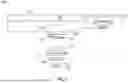
Referring to FIGS. 1 & 2, an exploded side view of a direct injection sink system 100 with a vortex blocking drain adapter 102 and an assembled side view of a direct injection sink system 100 with a vortex blocking drain adapter 102 are shown, according to examples of the present disclosure. A drain 104 may be disposed below the sink basin 106. In an exemplary implementation, the drain 104 may define a drain sidewall 108 extending from the sink basin 106 and terminating as a structure that defines an attachment bayonet 110. In an exemplary embodiment, the attachment bayonet 110 may define an annular flange 112 configured to directly engage a drain adapter 102 or garbage disposal. In another exemplary embodiment, the attachment bayonet 110 may define an annular flange 112 configured to engage with attachment hardware 113. The attachment hardware 113 may also engage the drain adapter 102 and a seal 115 to create a watertight connection between the drain 104 and drain adapter 102. Further, the drain sidewall 108 may define a fluid inlet stem 114 for connecting, such as by threaded engagement or press fit, a fluid line to the drain 104. The fluid line inlet stem 114 may allow for direct injection of a fluid, such as water, ozonated water, a cleaning solution, or a combination thereof, from a separate fluid source than the faucet, into the drain 104. Fluid may be injected into the drain 104, for example, to wash waste products down the drain, disinfect the drain, or otherwise clean the drain and other connected plumbing fixtures.
Additionally, the drain adapter 102 may define a geometry on a top side or portion 116 configured to attach to the drain attachment bayonet 110 either directly or with the attachment hardware 113. The geometry, for example, can be a lip, rim, threads, flange, or any other shape configured to engage with the flange 112, for example, on the attachment bayonet 110. The drain adapter 102 may define a geometry on a bottom side or portion 118 configured to attach to a drainpipe or garbage disposal, for example. In a non-limiting example, the top side 116 terminates in a shoulder 117 and the bottom side 118 extends below from a center of the shoulder 117, therefore creating a stepped transition. In another embodiment (not shown), the sidewall is tapered creating a continuous transition.
Similarly, the geometry on the bottom side 118 may comprise a lip, rim, threads, flange, or any other shape configured to engage with the drainpipe (illustrated as reference numeral 120 in FIG. 2) or garbage disposal. Further, the top side 116 of the drain adapter 102 may define a larger opening than the bottom side 118. As discussed infra, the drain adapter 102 may also comprise an internal geometry, like protrusions or depressions, for example, configured to disrupt a swirling vortex of injected fluid and prevent it from entering the sink basin.
Referring now to FIG. 3, a top perspective view of a direct injection sink system 100 with a vortex blocking drain adapter 102 is shown, according to examples of the present disclosure.
As previously described, the drain 104 may be disposed along the bottom of the sink basin 106. Also as previously described, the drain adapter 102 may be configured to attach to the drain 104 below the sink basin 106. As shown in FIG. 3, fluid 122 may be configured to be injected into the drain 104 and/or the drain adapter 102 from the fluid line inlet stem. The fluid 122 may comprise water, ozonated water, soap, or other disinfectant or cleaning fluid. The injected fluid 122 may clear waste that may be stuck to the sides of the drain 104 or drain adapter 102. Additionally, the fluid 122 may disinfect the interior surfaces of the drain 104, drain adapter 102, and subsequent plumbing fixtures in fluid communication with the drain. Accordingly, in some implementations it may be advantageous to inject the fluid 122 from multiple inlets and at different angles to create a swirling motion to ensure maximum coverage and cleaning power. However, too much swirling may create vortexes which can backflow into the sink basin, as discussed infra.
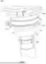
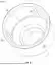
Referring now to FIG. 4, a top perspective view of a vortex blocking drain adapter 102 is shown, according to examples of the present disclosure. It is to be appreciated that the subsequently discussed flow disrupters could be disposed on the interior walls of the drain itself instead of, or in combination with, flow disrupters in the drain adapter 102, depending on where in the system the fluid is injected. For simplicity, only vortex blockers on the drain adapter 102 will be described, but this should be interpreted as including the drain itself or any other plumbing fixture below the sink basin.
As previously discussed, an issue with directly injecting pressurized fluid into the drain is the tendency for a vortex to form as the fluid circles an interior wall 124 of the drain adapter 102. As fluid is injected into the drain adapter 102, centrifugal force may cause the fluid to be pushed against the interior wall 124 of the drain adapter 102 where the fluid can collect and rise into the sink basin. This may create health and safety risks. For instance, if the fluid comprises a disinfectant, it may be harmful to a user of the sink if it contacts their skin or eyes, for example. Further, the fluid can carry bacteria or other contaminants into the sink basin, which might infect food, for example.
To prevent or reduce these issues, the drain adapter 102 may comprise at least one flow disrupter 126 disposed along the interior side wall 124 of the drain adapter 102. As shown in FIG. 4, in an exemplary implementation, the at least one flow disrupter 126 may comprise a plurality of protrusions extending from the interior side wall 124 towards a central axis C of the drain adapter 102. The protrusions may be configured to run substantially parallel to the central axis C such that swirling fluid is disrupted by the protrusions to reduce the fluid's momentum and prevent the fluid from rising into the sink basin. Alternatively, a protrusion in the form of a helix (not shown) may extend around a circumference of the drain adapter along at least a portion of its length.
In an exemplary implementation, the at least one flow disrupter 126 may be unitarily formed with the drain or drain adapter 102 by welding, injection molding, or sheet metal stamping, for example. In other implementations, the at least one flow disrupter 126 may comprise a separate component from the drain or drain adapter 102 and may be configured to attach to the drain or drain adapter via a slot or threaded connection, for example.
While linear protrusions are shown in FIG. 4, it is to be appreciated that other types of flow disruptors 126 may be implemented. For example, bumps, dimples, cavities, non-circular drain adapter 102 cross sections, or a rough surface finish may also be implemented to inhibit the flow of fluid across the interior side wall 124 to reduce the risk of the fluid rising into the sink basin.
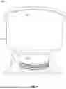
Referring now to FIG. 5, a side view of a vortex blocking drain adapter 102 is shown, according to examples of the present disclosure. As previously described, the drain adapter 102 may have a top side or end 116. The top side 116 may define a geometry configured to attach or engage the drain adapter 102 with a drain. In an exemplary implementation, the geometry may comprise a lip or ledge around an outer circumference of the drain adapter 102, but in other implementations, the geometry can comprise a rim, threads, flange, or any other shape configured to engage with the drain by way of an attachment bayonet, for example.
The vortex blocking drain adapter 102 also may comprise a bottom side 118 opposite from the top side 116. In an exemplary implementation, the bottom side 118 may define a smaller area than the top side 116. The bottom side 118 d may define a geometry configured to couple the drain adapter 102 with a drainpipe. In an exemplary implementation, the bottom side 118 geometry may define threads configured to threadedly engage a drainpipe. In other implementations, the bottom side 118 geometry may define a flange, lip, rim, or any other geometry to couple the drain adapter 102 to a drainpipe.
The vortex blocking drain adapter 102 may comprise a sidewall 124 disposed between the top side 116 and bottom side 118. In an exemplary implementation, the sidewall 124 may be oriented substantially vertical, which may further prevent a vortex of injected fluid from swirling out of the drain and into the sink basin.
Various examples of systems, devices, and methods have been described herein. These examples are given only by way of example and are not intended to limit the scope of the claimed inventions. It should be appreciated, moreover, that the various features of the embodiments that have been described may be combined in various ways to produce numerous additional embodiments. Moreover, while various materials, dimensions, shapes, configurations and locations, etc. have been described for use with disclosed embodiments, others besides those disclosed may be utilized without exceeding the scope of this disclosure.
Persons of ordinary skill in the relevant arts will recognize that the subject matter hereof may comprise fewer features than illustrated in any individual embodiment described above. The embodiments described herein are not meant to be an exhaustive presentation of the ways in which the various features of the subject matter hereof may be combined. Accordingly, the embodiments are not mutually exclusive combinations of features; rather, the various embodiments can comprise a combination of different individual features selected from different individual embodiments, as understood by persons of ordinary skill in the art. Moreover, elements described with respect to one embodiment can be implemented in other embodiments even when not described in such embodiments unless otherwise noted.
Although a dependent claim may refer in the claims to a specific combination with one or more other claims, other embodiments can also include a combination of the dependent claim with the subject matter of each other dependent claim or a combination of one or more features with other dependent or independent claims. Such combinations are proposed herein unless it is stated that a specific combination is not intended.
Any incorporation by reference of documents above is limited such that no subject matter is incorporated that is contrary to the explicit disclosure herein. Any incorporation by reference of documents above is further limited such that no claims included in the documents are incorporated by reference herein. Any incorporation by reference of documents above is yet further limited such that any definitions provided in the documents are not incorporated by reference herein unless expressly included herein.
For purposes of interpreting the claims, it is expressly intended that the provisions of 35 U.S.C. § 112(f) are not to be invoked unless the specific terms “means for” or “step for” are recited in a claim.
Claims
What is claimed is:1. A vortex blocking drain adapter comprising:
a sidewall extending from a first end to a second end, wherein an interior of the sidewall comprises structure defining a plurality of protrusions extending radially inwardly, and wherein the first end of the sidewall is configured to be coupled to a drain of a sink basin, and a second end is configured to be coupled to a drainpipe or garbage disposal.
2. The vortex blocking drain adapter of claim 1, wherein the plurality of protrusions comprises a plurality of vertical ribs.
3. The vortex blocking drain adapter of claim 1, wherein the first end of the sidewall has a diameter greater than a diameter of the second end of the sidewall.
4. The vortex blocking drain adapter of claim 3, wherein a first portion of the sidewall extends from the first end to a shoulder, and a second portion of the sidewall extends from the shoulder to the second end.
5. The vortex blocking drain adapter of claim 4, wherein an external surface of the second portion proximate the second end includes structure defining threading configured to engage with corresponding threading on an internal surface of the drainpipe or a garbage disposal.
6. The vortex blocking drain adapter of claim 1, wherein the first end of the sidewall is configured to couple to an attachment bayonet of the drain.
7. The vortex blocking drain adapter of claim 1, wherein the plurality of protrusions comprises ribs, bumps, dimples, cavities, or combinations thereof.
8. A drain system comprising:
a drain assembly extending from a bottom wall of a sink basin; and
a drain adapter operably coupled to the drain, the drain adapter having a sidewall including an interior surface comprising structure defining a plurality of protrusions extending radially inwardly, the drain adapter being configured to reduce or prevent formation of a vortex in the drain assembly.
9. The drain system of claim 8, therein the drain adapter comprises a first end coupleable to the drain assembly.
10. The drain system of claim 9, wherein the drain assembly comprises a direct inject drain assembly comprising a drain sidewall having a fluid inlet stem extending from an exterior surface of the drain sidewall, and plurality of nozzles in fluid communication with the fluid inlet stem, wherein the plurality of nozzles are configured to introduce streams of fluid directly into the drain assembly.
11. The drain system of claim 10, wherein the drain assembly further comprises a garbage disposal coupled to the drain adapter at a second end of the drain adapter opposite the first end.
12. The drain system of claim 9, wherein the drain adapter comprises a second end coupleable to a drainpipe or a garbage disposal.
13. The drain system of claim 12, wherein an exterior surface of the second portion proximate the second end includes structure defining threading configured to engage with corresponding threading on an internal surface of the drainpipe or a garbage disposal.
14. The drain system of claim 8, wherein the first end of the sidewall has a diameter greater than a diameter of a second end of the sidewall.
15. The drain system of claim 14, wherein a first portion of the sidewall extends from the first end to a shoulder, and a second portion of the sidewall extends from the shoulder to the second end.
16. The drain system of claim 8, wherein the plurality of protrusions comprises ribs, bumps, dimples, cavities, or combinations thereof.
17. A drain adapter comprising:
a sidewall removably coupleable to a drain assembly of a sink basin at a first end of the sidewall, and removably couplable to a drainpipe or a garbage disposal at a second end of the sidewall, wherein the drain adapter is configured to block formation of a vortex in the drain assembly to prevent fluid backflow into the sink basin.
18. The drain adapter of claim 17, wherein an interior of the sidewall includes structure defining one or more protrusions.
19. The drain adapter of claim 18, wherein the one or more protrusions comprise a plurality of vertically extending ribs.
20. The drain adapter of claim 18, wherein the one or more protrusions comprise a plurality of ribs, bumps, dimples, cavities, or combinations thereof.
Images & Drawings included:
Sources:
- United States Patent and Trademark Office - verify current appl. status at the USPTO↗
Recent applications in this class:
- » 20250369214 2025-12-04
SHOWER DRAIN ASSEMBLIES - » 20250347093 2025-11-13
SHOWER DRAIN AND PROTECTIVE COVER - » 20250341083 2025-11-06
ADJUSTABLE HEIGHT BATHTUB AND SHOWER DRAIN ASSEMBLY - » 20250109579 2025-04-03
SHOWER DRAIN ASSEMBLIES - » 20250084626 2025-03-13
SEWER LINE CONNECTION DEVICE - » 20250043554 2025-02-06
JOINT DEVICE FOR DRAIN PIPES - » 20240392547 2024-11-28
TILE WALL DRAIN - » 20240295103 2024-09-05
SINK SYSTEM WITH SEAMLESS DRAIN AND ATTACHMENT BAYONET - » 20230417030 2023-12-28
WASTE OUTLET - » 20230279650 2023-09-07
Sink Drain Pipe With and Without Overflow Ports