ADVANCING A BOTTOM HOLE ASSEMBLY INTO A WELLBORE
US20260085589A1
2026-03-26
19/321,514
2025-09-08
Smart Summary: A tubular string is placed into a section of a well that has holes for fluid to flow. A special agent is added to the fluid, which blocks some of the holes, making more fluid flow around the tubular string. This increased flow helps push the tubular string further down the well. The method can also involve blocking the upper holes while leaving the lower ones open to enhance the flow. Overall, this technique helps to move equipment deeper into the well more efficiently. 🚀 TL;DR
Abstract:
A method can include deploying a tubular string into a perforated section of a wellbore, and introducing a diverting agent into a fluid flow in an annulus surrounding the tubular string, the diverting agent blocking the fluid flow through a set of perforations in the perforated section, thereby increasing a flow rate of the fluid flow in the annulus surrounding the tubular string and advancing the tubular string through the wellbore. Another method can include deploying a tubular string into a perforated section of a wellbore, the perforated section including multiple sets of perforations, a first set of the perforations being positioned uphole of a second set of the perforations, and blocking the first set of the perforations, thereby increasing a flow rate of fluid flow in an annulus surrounding the tubular string and advancing the tubular string through the wellbore.
Inventors:
- Roger L. Schultz 107 🇺🇸 Ninnekah, OK, United States
- Bradley J. Miller 3 🇺🇸 Joliet, MT, United States
Applicant:
Interested in similar patents?
Get notified when new applications in this technology area are published.
Classification:
E21B19/08 » CPC main
Handling rods, casings, tubes or the like outside the borehole, e.g. in the derrick; Apparatus for feeding the rods or cables Apparatus for feeding the rods or cables ; Apparatus for increasing or decreasing the pressure on the drilling tool; Apparatus for counterbalancing the weight of the rods
E21B28/00 » CPC further
Vibration generating arrangements for boreholes or wells, e.g. for stimulating production
Description
CROSS-REFERENCE TO RELATED APPLICATION
This application claims the benefit of U.S. provisional application No. 63/697,773 filed on 23 Sep. 2024. The entire disclosure of the prior application is incorporated herein by this reference for all purposes.
BACKGROUND
This disclosure relates generally to equipment utilized and operations performed in conjunction with a subterranean well and, in an example described below, more particularly provides for advancing a bottom hole assembly into a wellbore.
In well operations in which a tubular string is deployed in a wellbore, it is frequently desirable to be able to displace the tubular string through the wellbore. However, circumstances can arise in which it can be difficult to displace the tubular string in the wellbore.
It will, therefore, be readily appreciated that advancements are continually needed in the art of preferring well operations that require advancement of a tubular string in a wellbore. The present disclosure provides such advancements to the art, which may be used with a wide variety of different types of well operations.
BRIEF DESCRIPTION OF THE DRAWINGS
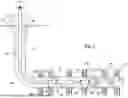
FIG. 1 is a representative partially cross-sectional view of an example of a well system and associated method which can embody principles of this disclosure.
FIG. 2 is a representative partially cross-sectional view of the well system, in which fluid and a diverting agent are pumped through an annulus.
DETAILED DESCRIPTION
Representatively illustrated in the accompanying drawings is a system 10 for use with a subterranean well, and an associated method, which can embody principles of this disclosure. However, it should be clearly understood that the system 10 and method are merely one example of an application of the principles of this disclosure in practice, and a wide variety of other examples are possible. Therefore, the scope of this disclosure is not limited at all to the details of the system 10 and method described herein and/or depicted in the drawings.
In one aspect, this disclosure describes systems and methods of advancing a bottom hole assembly into a wellbore. One use of this system and method is to assist in milling frac plugs or general cleaning in long horizontal laterals. Other uses and purposes are also provided for.
An example workstring advancement method consists of milling plugs with an appropriate motor boom hole assembly by advancing coiled tubing or jointed pipe in a conventional manner, and flushing the wellbore and plug debris up the annulus and to the surface. When it becomes difficult to advance the bottom hole assembly into the well due to mechanical friction, etc., fluid is then pumped down the annulus between the workstring and casing from the surface to create downward drag on the workstring, which creates a downward force on the workstring, helping to advance the workstring and bottom hole assembly into the well.
The pumped fluid flows down the annulus and into open perforations in the wellbore. Fluid is also pumped simultaneously down the workstring to operate the motor bottom hole assembly as it is advanced into the wellbore. This sequence of drilling plugs and circulating debris to the surface, then pumping down the annulus can be repeated any number of times, until well operations are completed.
The system and method disclosed herein can in some embodiments include pumping a diverting agent down with the annular fluid to reduce flow of the pumped fluid into perforations higher in the well, so that higher fluid velocities and, hence, higher drag force are exposed to a longer section of the workstring. This increased drag force helps advance the workstring and bottom hole assembly into the wellbore more effectively. Any suitable diverting agent can be used, such as, particulate diverters or plugging devices of the type described in U.S. Pat. Nos. 9,551,204, 11,242,727, 10,851,615, 9,523,267, 9,567,824, 9,567,825, 9,567,826, 10,655,427, 10,233,719, 9,745,820, 9,816,341, 10,871,049 and 11,859,317, the entire disclosures of which are incorporated herein by this reference for all purposes.
In one example, the diverting agent or plugging devices may be degradable in the well. The diverting agent or plugging devices may be used as described above with at least one vibratory tool included in the bottom hole assembly.
The vibratory tool may be selectively activated. Suitable vibratory tools include, but are not limited to, those described in U.S. Pat. Nos. 9,957,765, 11,753,901 and 11,525,307, and US publication no. 2024/0384616, the entire disclosures of which are incorporated herein by this reference for all purposes.
A diverting agent or plugging devices may be used as described herein with at least two vibratory tools installed in the bottom hole assembly/workstring assembly. The diverting agent or plugging devices may be used with at least two vibratory tools installed in the bottom hole assembly/workstring assembly, and at least one of the vibratory tools may be selectively activated.
In some examples, removal of the diverting agent or plugging devices can be accomplished by milling, back-reaming or washing with the bottom hole assembly, without removing the bottom hole assembly from the wellbore (in a single trip into the wellbore).
The vibratory tools described herein can be located anywhere in the workstring and any number of vibratory tools may be used. Individual vibratory tools can be activated or deactivated independently.
Referring specifically now to FIG. 1, a representative partially cross-sectional view of an example of the well system 10 and method is depicted. In this example, a tubular string 12 is deployed into a wellbore 14. The wellbore 14 may be lined with casing and cement (not shown).
The tubular string 12 may in this example comprise pipe, jointed tubing or continuous coiled tubing. The tubular string 12 may be conveyed through the wellbore 14 by means of an injector (in the case of coiled tubing), a snubbing unit, a downhole tractor, and/or by its own weight (such as, in a vertical section of the wellbore).
In the FIG. 1 example, the tubular string 12 includes multiple bottom hole assemblies 16, 18. In other examples, only a single bottom hole assembly may be used.
The bottom hole assembly 16 includes a vibratory tool 20. The vibratory tool 20 is designed to produce vibrations in the tubular string 12, for example, in response to flow of a fluid 24 through the tubular string. The vibratory tool 20 may be selectively activated, such as, when the tubular string 12 is received in a generally horizontal section of the wellbore 14, and friction between the tubular string and the wellbore makes it difficult to further advance the tubular string into the wellbore. The vibratory tool 20 may also be selectively deactivated, such as, when the tubular string 12 is initially deployed into, or retrieved from, the wellbore 14.
The bottom hole assembly 16 can also include other well tools 22, such as, logging or other measurement tools, ranging equipment, a reamer, a jetting tool, etc. The scope of this disclosure is not limited to any particular number, types or combination of tools in the bottom hole assembly 16.
The bottom hole assembly 18 includes another vibratory tool 26 and a fluid motor 28. The vibratory tool 28 may be similar to, or different from, the vibratory tool 20 of the bottom hole assembly 16.
The fluid motor 28 may comprise a turbine-type or Moineau-type motor that produces rotation in response to flow of the fluid 24 through the fluid motor. This rotation is transmitted (such as, via a bearing assembly, not shown) to a drill bit 30 connected at a distal end of the bottom hole assembly 18.
In other examples, the bottom hole assembly 18 may comprise other or different well tools (such as, logging tools, ranging equipment, a reamer, a jetting tool, etc.). The scope of this disclosure is not limited to any particular number, types or combination of tools in the bottom hole assembly 18.
In the FIG. 1 example, the drill bit 30 is used to drill or mill through one or more plugs 32 (such as, “frac” plugs or bridge plugs) previously set in the wellbore 14. In other examples, the tubular string 12 may not be used in a plug drilling operation, in which case the drill bit 30 may not be used, or the drill bit may be used for another purpose.
As depicted in FIG. 1, the wellbore 14 has an initial generally vertical section and a further downhole generally horizontal section. It will be appreciated that in most circumstances the tubular string 12 can be readily conveyed through the vertical section, but that friction hindering further conveyance of the tubular string into the wellbore 14 will increase when the tubular string enters the horizontal section.
In this example, the vibratory tools 20, 26 can help to alleviate the friction between the tubular string 12 and the wellbore 14. The vibratory tools 20, 26 may be activated (individually or at separate times) when the tubular string 12 enters the horizontal section, or at any time conveyance of the tubular string through the wellbore 14 becomes difficult.
As depicted in FIG. 1, the horizontal section of the wellbore 14 is perforated in multiple locations. In this example, perforations 34 are formed extending outward from the wellbore 14, so that fluid communication is permitted via the perforations between the wellbore and an earth formation penetrated by the wellbore.
The fluid 24 is circulated downhole through the tubular string 12, outward from the tubular string via nozzles (not shown) in the drill bit 30, and back to surface via an annulus 36 formed between the tubular string and the wellbore 14. If the tubular string 12 is received in another tubular string (not shown) surrounding the tubular string 12, then the annulus 36 may be formed between the two tubular strings.
Referring additionally now to FIG. 2, a representative partially cross-sectional view of an example of the system 10 and method is depicted. In this view, the tubular string 12 is advanced further into the wellbore 14, so that the drill bit 30 will contact and cut through one of the plugs 32.
The flow of the fluid 24 through the tubular string 12 causes the fluid motor 28 to rotate the drill bit 30. One or both of the vibratory tools 20, 26 may also be activated at this point to cause vibrations to be produced in the tubular string 12.
However, operation of the vibratory tools 20, 26 may not be sufficient to permit the tubular string 12 to be advanced, so that enough force is applied to the drill bit 30 to cut through the plug 32. It would be beneficial in this example to be able to apply a fluid drag force to the tubular string 12. The fluid drag force would assist in advancing the tubular string 12 further through the wellbore 14.
As depicted in FIG. 2, a fluid 38 is pumped into the annulus 36 at the surface. The fluid 38 flows through the annulus 36 surrounding the tubular string 12, which thereby produces a downhole directed fluid drag force on the tubular string. The fluid 38 can flow out of the wellbore 14 via the perforations 34.
Note that the fluid 38 may be of the same type as the fluid 24 flowed through the tubular string 12. Alternatively, a different fluid 38 may be flowed through the annulus 36 as compared to the fluid 24 flowed through the tubular string 12.
To enhance the fluid drag force applied to the tubular string 12, a flow rate of the fluid 38 can be increased in the annulus 36 surrounding a portion of the tubular string. In the FIG. 2 example, the flow rate in the annulus 36 surrounding the lower bottom hole assembly 18 is increased by blocking flow of the fluid 38 into perforations 34 uphole of the bottom hole assembly 18. This forces substantially all of the fluid 38 to flow through the perforations 34 that remain unblocked. The unblocked perforations 34 in this example are downhole of the perforations that are blocked.
To block flow of the fluid 38 through the uphole set of perforations 34, a diverting agent 40 is deployed into the annulus 36, so that the diverting agent is conveyed through the annulus with the flow of the fluid. The diverting agent 40 may comprise individual plugging devices (as depicted in FIG. 2), a particulate diverter (such as, poly-lactic acid, calcium carbonate, etc.) or another substance suitable for blocking flow through perforations 34.
As depicted in FIG. 2, the diverting agent 40 blocks flow of the fluid 38 outward through an uphole set of the perforations 34. A further downhole set of the perforations 34 remain unblocked. It will be appreciated that a flow rate through the unblocked perforations 34 is greater when the uphole set of perforations are blocked than it would be if the uphole set of perforations had remained unblocked.
After the plug 32 has been drilled through, the flow of the fluid 38 through the annulus 36 may be ceased, thereby allowing the fluid 24 to flow uphole via the annulus (e.g., as depicted in FIG. 1). This annulus flow may be used to circulate debris and cuttings out of the wellbore 14.
The flow of the fluid 38 through the annulus 36 may then be resumed, in order to further advance the tubular string 12 through the wellbore 14, for example, to drill through a next plug 32. This cycle of flowing the fluid 38 through the annulus 36 to assist in advancing the tubular string 12 through the wellbore 14, and then ceasing flow of the fluid 38 (e.g., to allow debris and cuttings to be circulated out of the wellbore) can be repeated as many times as needed or desired to drill through any number of plugs 32 in this example.
When it is no longer desired to block flow through the perforations 34, the diverting agent 40 may be dislodged or cut, for example, using a reamer, the drill bit 30 or other suitable tool connected in the tubular string 12. Alternatively, the diverting agent 40 may be degraded in the well, for example, by circulating an acid or other degrading substance to the blocked perforations 34, allowing the diverting agent to degrade over time, dissolve, corrode or melt, etc.
In some examples, multiple plugs 32 can be drilled through in a single trip of the tubular string 12 into the wellbore 14. After one plug 32 is drilled through, additional diverting agent 40 may be deployed into the annulus 36 with the flow of the fluid 38 to thereby block flow through additional perforations 34.
It may now be fully appreciated that the present disclosure provides significant advancements to the art of performing well operations in which advancement of a tubular string through a wellbore is desired. In examples described herein, a fluid drag force is applied to a portion of the tubular string 12 by flowing the fluid 38 downhole through the annulus 36. The drag force on the portion of the tubular string 12 is increased by blocking flow of the fluid 38 through an uphole set of the perforations 34, thereby increasing a flow rate of the fluid about the portion of the tubular string.
The present disclosure provides to the art a method for use with a subterranean well. In one example, the method can comprise: deploying a tubular string 12 into a perforated section of a wellbore 14; and introducing a diverting agent 40 into a fluid 38 flow in an annulus 36 surrounding the tubular string 12, the diverting agent 40 blocking the fluid 38 flow through a first set of perforations 34 in the perforated section, thereby increasing a flow rate of the fluid 38 flow in the annulus 36 surrounding the tubular string 12 and advancing the tubular string 12 through the wellbore 14.
The tubular string 12 may include one or multiple vibratory tool(s) 20, 26.
The first set of the perforations 34 blocked by the diverting agent 40 may be positioned uphole relative to a second set of the perforations 34 that are not blocked by the diverting agent 40.
The flow rate increasing may include increasing a fluid drag force on the tubular string 12.
The tubular string 12 may include a bottom hole assembly 16, 18. The bottom hole assembly 18 may include a fluid motor 28 and a drill bit 30.
The method may include flowing a fluid 24 through the fluid motor 28 and the drill bit 30 prior to or after the diverting agent 40 introducing step. The method may include flowing a fluid 24 through the fluid motor 28 and the drill bit 30 concurrently with the advancing step.
The method may include, after the tubular string 12 advancing step, the diverting agent 40 degrading in the well, thereby unblocking the first set of the perforations 34. The method may include, after the tubular string 12 advancing step, dislodging the diverting agent 40 with the tubular string 12, thereby unblocking the first set of the perforations 34.
Another example method described herein can comprise: deploying a tubular string 12 into a perforated section of a wellbore 14, the perforated section comprising first and second sets of perforations 34, the first set of perforations 34 being positioned uphole of a second set of the perforations 34; and blocking the first set of the perforations 34, thereby increasing a flow rate of fluid 38 flow in an annulus 36 surrounding the tubular string 12 and advancing the tubular string 12 through the wellbore 14.
The blocking step may include introducing a diverting agent 40 into the fluid 38 flow. The diverting agent 40 may comprise multiple plugging devices or a particulate diverter.
The method may include, after the tubular string 12 advancing step, the diverting agent 40 degrading in the well, thereby unblocking the first set of the perforations 34. The method may include, after the tubular string 12 advancing step, dislodging the diverting agent 40 with the tubular string 12, thereby unblocking the first set of the perforations 34.
The tubular string 12 may include one or more vibratory tool(s) 20, 26.
The second set of the perforations 34 may not be blocked prior to the tubular string 12 advancing step.
The flow rate increasing step may include increasing a fluid drag force on the tubular string 12.
The tubular string 12 may include a bottom hole assembly 16, 18. The bottom hole assembly 18 may include a fluid motor 28 and a drill bit 30. The method may include flowing a fluid 24 through the fluid motor 28 and the drill bit 30 prior to or after the blocking step. The method may include flowing a fluid 24 through the fluid motor 28 and the drill bit 30 concurrently with the advancing step.
Although various examples have been described above, with each example having certain features, it should be understood that it is not necessary for a particular feature of one example to be used exclusively with that example. Instead, any of the features described above and/or depicted in the drawings can be combined with any of the examples, in addition to or in substitution for any of the other features of those examples. One example's features are not mutually exclusive to another example's features. Instead, the scope of this disclosure encompasses any combination of any of the features.
Although each example described above includes a certain combination of features, it should be understood that it is not necessary for all features of an example to be used. Instead, any of the features described above can be used, without any other particular feature or features also being used.
It should be understood that the various embodiments described herein may be utilized in various orientations, such as inclined, inverted, horizontal, vertical, etc., and in various configurations, without departing from the principles of this disclosure. The embodiments are described merely as examples of useful applications of the principles of the disclosure, which is not limited to any specific details of these embodiments.
In the above description of the representative examples, directional terms (such as “above,” “below,” “upper,” “lower,” “upward,” “downward,” etc.) are used for convenience in referring to the accompanying drawings. However, it should be clearly understood that the scope of this disclosure is not limited to any particular directions described herein.
The terms “including,” “includes,” “comprising,” “comprises,” and similar terms are used in a non-limiting sense in this specification. For example, if a system, method, apparatus, device, etc., is described as “including” a certain feature or element, the system, method, apparatus, device, etc., can include that feature or element, and can also include other features or elements. Similarly, the term “comprises” is considered to mean “comprises, but is not limited to.”
Of course, a person skilled in the art would, upon a careful consideration of the above description of representative embodiments of the disclosure, readily appreciate that many modifications, additions, substitutions, deletions, and other changes may be made to the specific embodiments, and such changes are contemplated by the principles of this disclosure. For example, structures disclosed as being separately formed can, in other examples, be integrally formed and vice versa. Accordingly, the foregoing detailed description is to be clearly understood as being given by way of illustration and example only, the spirit and scope of the invention being limited solely by the appended claims and their equivalents.
Claims
What is claimed is:1. A method for use with a subterranean well, the method comprising:
deploying a tubular string into a perforated section of a wellbore; and
introducing a diverting agent into a fluid flow in an annulus surrounding the tubular string, the diverting agent blocking the fluid flow through a first set of perforations in the perforated section, thereby increasing a flow rate of the fluid flow in the annulus surrounding the tubular string and advancing the tubular string through the wellbore.
2. The method of claim 1, in which the tubular string comprises at least one vibratory tool.
3. The method of claim 1, in which the tubular string comprises multiple vibratory tools.
4. The method of claim 1, in which the first set of the perforations blocked by the diverting agent are positioned uphole relative to a second set of the perforations that are not blocked by the diverting agent.
5. The method of claim 1, in which the flow rate increasing comprises increasing a fluid drag force on the tubular string.
6. The method of claim 1, in which the tubular string comprises a bottom hole assembly, and the bottom hole assembly comprises a fluid motor and a drill bit.
7. The method of claim 6, further comprising flowing a fluid through the fluid motor and the drill bit prior to the diverting agent introducing.
8. The method of claim 6, further comprising flowing a fluid through the fluid motor and the drill bit after the diverting agent introducing.
9. The method of claim 6, further comprising flowing a fluid through the fluid motor and the drill bit concurrently with the advancing.
10. The method of claim 1, further comprising, after the tubular string advancing, the diverting agent degrading in the well, thereby unblocking the first set of the perforations.
11. The method of claim 1, further comprising, after the tubular string advancing, dislodging the diverting agent with the tubular string, thereby unblocking the first set of the perforations.
12. A method for use with a subterranean well, the method comprising:
deploying a tubular string into a perforated section of a wellbore, the perforated section comprising first and second sets of perforations, the first set of perforations being positioned uphole of a second set of the perforations; and
blocking the first set of the perforations, thereby increasing a flow rate of fluid flow in an annulus surrounding the tubular string and advancing the tubular string through the wellbore.
13. The method of claim 12, in which the blocking comprises introducing a diverting agent into the fluid flow.
14. The method of claim 13, in which the diverting agent comprises multiple plugging devices.
15. The method of claim 13, in which the diverting agent comprises a particulate diverter.
16. The method of claim 13, further comprising, after the tubular string advancing, the diverting agent degrading in the well, thereby unblocking the first set of the perforations.
17. The method of claim 13, further comprising, after the tubular string advancing, dislodging the diverting agent with the tubular string, thereby unblocking the first set of the perforations.
18. The method of claim 12, in which the tubular string comprises at least one vibratory tool.
19. The method of claim 12, in which the tubular string comprises multiple vibratory tools.
20. The method of claim 12, in which the second set of the perforations is not blocked prior to the tubular string advancing.
21. The method of claim 12, in which the flow rate increasing comprises increasing a fluid drag force on the tubular string.
22. The method of claim 12, in which the tubular string comprises a bottom hole assembly, and the bottom hole assembly comprises a fluid motor and a drill bit.
23. The method of claim 22, further comprising flowing a fluid through the fluid motor and the drill bit prior to the blocking.
24. The method of claim 22, further comprising flowing a fluid through the fluid motor and the drill bit after the blocking.
25. The method of claim 22, further comprising flowing a fluid through the fluid motor and the drill bit concurrently with the advancing.
Images & Drawings included:


Sources:
- United States Patent and Trademark Office - verify current appl. status at the USPTO↗
Similar patent applications:
Recent applications in this class:
- » 20250305375 2025-10-02
MODULAR WELL TUBULAR HANDLING SYSTEM AND METHOD OF USE - » 20240384611 2024-11-21
OVERHEAD ROBOT TRACK APPARATUS AND METHODS RELATED TO SAME FOR RIGS - » 20240376790 2024-11-14
PIPE HANDLING SYSTEM - » 20220003050 2022-01-06
Rod handler apparatus in core drilling - » 20210262299 2021-08-26
Gripper assembly for a coiled tubing injector - » 20210172267 2021-06-10
Swivel assembly for drilling machine - » 20200199947 2020-06-25
Cable pusher and related methods - » 20200157892 2020-05-21
Core tube displacer for long reach drilling machines - » 20200095835 2020-03-26
SYSTEM AND METHOD FOR MONITORING AND ADJUSTMENT OF THE WELL STRING POSITIONING WITHIN A WELL TUBULAR - » 20190360284 2019-11-28
Mobile coiled tubing drilling apparatus