AIR-CONDITIONING DEVICE CONFIGURED TO OPERATE IN DUAL MODE
US20260085845A1
2026-03-26
19/343,990
2025-09-29
Smart Summary: An air-conditioning device can work in two different modes. It has an outdoor unit that includes a compressor, a condenser, and a fan to manage air intake and discharge. The indoor unit contains an evaporator and another fan to circulate cool air inside a room. There is also a control panel for users to adjust settings easily. A battery is included in the outdoor unit to provide power when needed. 🚀 TL;DR
Abstract:
The present invention provides an air-conditioning device configured to operate in a dual mode, the air-conditioning device comprising an outdoor unit (10), an indoor unit (20), and a battery (30). The outdoor unit (10) comprises: an outdoor unit body (11) having multiple first outdoor unit intake holes (111) formed through left and right surface portions thereof, and having multiple heated air discharge holes (113) formed through the rear upper portion thereof; a containing body (13) having an open front portion, having a containing space (131) formed therein, and having multiple second outdoor unit intake holes (133) formed through left and right surface portions thereof, the containing body (13) protruding forward from the front portion of the outdoor unit body (11) by a predetermined length; a compressor (12) provided in the inner front portion of the outdoor unit body (11); a condenser (14) connected to the compressor (12) and provided on one side portion of the inner rear side of the outdoor unit body (11) while being spaced apart from the first outdoor unit intake holes (111) by a predetermined interval; an outdoor unit connector (15) protruding from a rear barrier (132) in the containing space (131) of the containing body (13); and an outdoor unit blowing fan (16) provided on the other side portion of the inner rear side of the outdoor unit body (11) while being spaced apart from the heating air discharge holes (113) by a predetermined interval. The indoor unit (20) comprises: an indoor unit body (21) having a containing space provided therein with a predetermined size, having multiple indoor unit intake holes (211) formed through left and right surface portions thereof, and having a cooling air discharge hole (213) formed through the front upper portion thereof; a manipulation panel (23) provided on the front lower portion of the indoor unit body (21) or on the upper front center portion thereof; an evaporator (22) provided on one side portion inside the indoor unit body (21) while being spaced apart from the indoor unit intake holes (211) by a predetermined interval; an indoor unit blowing fan (24) provided on the other side portion inside the indoor unit body (21) so as to discharge cooling air through the cooling air discharge hole (213); and an indoor unit connector (25) protruding from the rear center portion of the indoor unit body (21). The battery (30) is embedded in the lower portion of the outdoor unit body (11).
Applicant:
Interested in similar patents?
Get notified when new applications in this technology area are published.
Classification:
F24F1/32 » CPC further
Room units for air-conditioning, e.g. separate or self-contained units or units receiving primary air from a central station; Separate outdoor units, e.g. outdoor unit to be linked to a separate room comprising a compressor and a heat exchanger; Refrigerant piping for connecting the separate outdoor units to indoor units
F24F11/89 » CPC further
Control or safety arrangements Arrangement or mounting of control or safety devices
F24F13/22 » CPC further
Details common to, or for air-conditioning, air-humidification, ventilation or use of air currents for screening Means for preventing condensation or evacuating condensate
F24F1/04 » CPC main
Room units for air-conditioning, e.g. separate or self-contained units or units receiving primary air from a central station; Self-contained room units for air-conditioning, i.e. with all apparatus for treatment installed in a common casing Arrangements for portability
Description
CROSS-REFERENCE TO RELATED APPLICATIONS
This application is a Continuation of Application No. PCT/KR2023/011001, filed on Jul. 27, 2023, which in turn claims the benefit of Korean Patent Application No. 10-2023-0048065, filed on Apr. 12, 2023. The entire disclosures of all these applications are hereby incorporated by reference.
TECHNICAL FIELD
The present invention relates to an air conditioner, and more particularly, to an air conditioner configured to operate in a dual mode, capable of selectively using an outdoor unit and an indoor unit in a combined manner or in a separated manner depending on a physical environment of a space requiring cooling, and not only ensuring stable cooling performance by charging a refrigerant, but also rapidly discharging condensate generated during a cooling process to the outside through an outdoor unit.
BACKGROUND ART
An air conditioner is a device that appropriately regulates the temperature and humidity of air in a specific space by condensing a refrigerant from a gaseous state into a liquid state, and then restoring the refrigerant to the gaseous state inside an evaporator, thereby exchanging heat with surrounding air, and in particular, during hot and humid summers, the air conditioner has long been an essential appliance in homes as well as offices, and in recent years, its demand has further increased with global warming.
Typically, this air conditioner includes an indoor unit located in an indoor space to perform heat exchange between indoor air and a refrigerant and an outdoor unit located in an outdoor space to perform heat exchange between outdoor air and the refrigerant, and is classified into a split-type or an integrated-type depending on whether the indoor unit and the outdoor unit are formed in an integrated structure.
The former, the split-type, has the advantage of providing excellent cooling capacity, but in order to realize this advantage, not only the indoor unit but also the outdoor unit need to be relatively large, which makes installation difficult. In contrast, the latter, the integrated-type, has the disadvantage that its cooling capacity is relatively lower than that of the former, but due to its structural characteristic of being formed in an integrated structure, the size is a compact size, which makes installation very easy.
For this reason, the air conditioner in which the outdoor unit and the indoor unit are formed in an integrated structure is widely used in small spaces and simple facilities. However, although the integrated-type air conditioner is as compact as possible, due to the characteristics of outdoor unit components that are relatively heavy, it is considerably difficult for a user to conveniently carry the integrated-type air conditioner to different locations and use it as needed, instead of using the integrated-type air conditioner in an installed state in a fixed building.
To this end, as disclosed in FIG. 11 by way of example, many technologies that enhance portability for users by densely arranging components while significantly reducing the overall weight have been suggested. However, since most of the technologies currently suggested, including the technology shown in FIG. 11, have an integrated structure in which the indoor unit and the outdoor unit are formed, there is a problem in that the cooling efficiency is reduced since heat exchange by the outdoor unit is also performed through the air of the indoor space serving as the cooling target.
DISCLOSURE
Technical Problem
The present invention has been made to overcome the problem of the related art, and an object of the present invention is to provide an air conditioner that is not only capable of being downsized to enhance portability, but also capable of being selectively used either in a coupled state or a separated state of an outdoor unit and an indoor unit, and further capable of providing stable cooling capacity over a long period of time.
Technical Solution
In order to achieve the object, the present invention provides an air conditioner configured to operate in a dual mode, including an outdoor unit (10) including an outdoor unit body (11) having a plurality of first outdoor unit intake holes (111) formed in left and right side surface portions thereof, and having a plurality of heated air discharge holes (113) formed in an upper portion of a rear surface thereof, a receiving body (13) having an open front portion, having a receiving space (131) formed therein, and having a plurality of second outdoor unit intake holes (133) formed in side surface portions thereof, wherein the receiving body (13) protrudes forward from a front surface portion of the outdoor unit body (11) by a predetermined length, a compressor (12) provided in a front portion inside the outdoor unit body (11), a condenser (14) connected to the compressor (12) and provided on one side of a rear portion inside the outdoor unit body (11) while being spaced apart from the first outdoor unit intake holes (111) by a predetermined distance, an outdoor unit connector (15) protruding from a rear partition wall (132) in the receiving space (131) of the receiving body (13), and an outdoor unit blower fan (16) provided on the other side of the rear portion inside the outdoor unit body (11) while being spaced apart from the heated air discharge holes (113) by a predetermined distance, an indoor unit (20) including an indoor unit body (21) having an internal space of a predetermined size, having a plurality of indoor unit intake holes (211) formed in left and right side surface portions thereof, and having a cooled air discharge hole (213) formed in an upper portion of a front surface thereof, a control panel (23) provided on a lower portion of a front surface of the indoor unit body (21) or on a front central portion of an upper surface thereof, an evaporator (22) provided on one side inside the indoor unit body (21) while being spaced apart from the indoor unit intake holes (211) by a predetermined distance, an indoor unit blowing fan (24) provided on the other side inside the indoor unit body (21) to discharge cooling air through the cooled air discharge hole (213), and an indoor unit connector (25) protruding from a central portion of a rear surface of the indoor unit body (21), and a battery (30) built into a lower portion of the outdoor unit body (11), wherein the indoor unit (20) operates by connecting the indoor unit connector (25) to the outdoor unit connector (15) when the indoor unit body (21) is inserted through the receiving body (13) of the outdoor unit (10), and operates by connecting both ends of the connecting tube (40) to the indoor unit connector (25) and the outdoor unit connector (15), respectively, when the inserted indoor unit (20) is separated from the outdoor unit (10).
An upper portion of the receiving space (131) of the receiving body (13) may be open.
In the outdoor unit connector (15), first and second outdoor unit refrigerant connection portions (151 and 153), an outdoor unit drain pipe connection portion (155), and an outdoor unit electric-wire connection portion (157) may be each provided, and in the indoor unit connector (25), first and second indoor unit refrigerant connection portions (251 and 253), an indoor unit drain pipe connection portion (255), and an indoor unit electric-wire connection portion (257) may be each provided.
An auxiliary outdoor unit connector (150) may be provided on the other side of the outdoor unit body (11).
An opening/closing door (19) may be provided on one side of the receiving body (13) and a compression ring (27) that has a threaded engagement portion formed on an inner surface thereof and is rotatably coupled to an outer surface of the indoor unit connector (25) may be provided on the outer surface of the indoor unit connector (25) so that the indoor unit connector (25) may be connected to or disconnected from the outdoor unit connector (15) by rotating the pressing ring (27) in one direction or the other direction.
In addition, in this case, a refrigerant charging port (17) may protrude from a portion on one side of the rear partition wall (132) inside the receiving body (13) spaced apart from the outdoor unit connector (15) by a predetermined distance, and the refrigerant charging port (17) may communicate with a connecting pipe (154) connecting the condenser (14) and the second outdoor unit refrigerant connection portion (153) by a bypass pipe (171).
In addition, in this case, a condensate collection pan (26) may be provided in a lower portion inside the indoor unit body (21), each of the evaporator (22) and the indoor unit blower fan (24) may be installed on an upper surface portion of the condensate collection pan (26), the condensate collection pan (26) and the indoor unit drain pipe connection portion (255) may be connected to each other by a connecting hose (28), a drain hose (18) may be provided on the outdoor unit 10, and one end of the drain hose (18) may be connected to the outdoor unit drain pipe connection portion (155) and the other end thereof may extend through a rear surface portion of the outdoor unit body (11).
When the control panel (23) of the indoor unit (20) is provided in a front central portion of an upper surface of the indoor unit body (21), a handle groove (29) may be formed in a lower portion of the cooled air discharge hole (213).
A leg plate (215) having a structure in which a vertical height of a front portion is greater than a vertical height of a rear portion may be provided in a foldable manner on a lower surface portion of the indoor unit body (21).
Advantageous Effects
The present invention can be configured such that an indoor unit operates while inserted into the outdoor unit at a predetermined depth or operates while separated from the outdoor unit, thereby not only facilitating storage and transportation but also enabling selection of the most appropriate operating mode depending on the physical environment of a space requiring cooling.
In addition, in the present invention, an opening/closing door is provided on a side portion of an outdoor unit adjacent to an outdoor unit connector, and a compression ring is provided on an indoor unit connector of an indoor unit, so that, when the indoor unit operates while inserted into the outdoor unit, a stable coupling state between the outdoor unit connector and the indoor unit connector can be maintained, and the indoor unit can be very readily separated from the outdoor unit.
In addition, in the present invention, by providing an injection port for charging a refrigerant on an outdoor unit, long-term stable cooling performance can be ensured, and by providing a condensate collection pan and a drain hose in each of the indoor unit and the outdoor unit, condensate generated during a cooling process can be rapidly discharged through the outdoor unit.
DESCRIPTION OF DRAWINGS
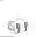
FIG. 1 is a schematic configuration view showing a case in which an indoor unit operates while inserted into an outdoor unit in an air conditioner according to the present invention.
FIG. 2A is a schematic configuration view showing a state in which the indoor unit is separated from the outdoor unit in the air conditioner according to the present invention.
FIG. 2B is a schematic configuration view showing a case in which the indoor unit operates while connected by a connecting tube and separated from the outdoor unit in FIG. 2A.
FIG. 3 is a schematic view showing a configuration in which the indoor unit and the outdoor unit are connected to each other using a compression ring in the air conditioner according to the present invention.
FIG. 4 is a schematic configuration view showing the interior of the outdoor unit in the air conditioner according to the present invention.
FIG. 5 is a schematic configuration view showing the interior of the indoor unit in the air conditioner according to the present invention.
FIG. 6 is a schematic configuration view showing another example of the outdoor unit in the air conditioner according to the present invention.
FIG. 7A is a schematic configuration view showing still another example of the outdoor unit in the air conditioner according to the present invention.
FIG. 7B is a schematic configuration view showing a case in which the indoor unit operates while connected by a connecting tube and separated from the outdoor unit in FIG. 7A.
FIGS. 8A and 8B are schematic configuration views each showing another example of indoor units in the air conditioner according to the present invention.
FIG. 9 is a schematic view showing a refrigerant charging process in an air conditioner according to the present invention.
FIG. 10 is a schematic operation configuration diagram of a leg plate provided in an indoor unit in an air conditioner according to the present invention.
FIG. 11 is a schematic view of a conventional mobile air conditioner.
BEST MODE
A preferred embodiment of the present invention will be described in detail below with reference to the attached drawings, and when describing the embodiments of the present invention, detailed description of matters that are not directly related to the technical features of the present invention or are obvious to those skilled in the art in the technical field to which the present invention pertains will be omitted.
The present invention relates to an air conditioner, and includes an outdoor unit 10, an indoor unit 20 that operates while inserted into the outdoor unit 10 or operates via a connecting tube 40 while separated therefrom, and a battery 30. Hereinafter, each of these configurations will be described in detail.
The outdoor unit 10 is a portion that forms a main body in the present invention, and is a portion that compresses refrigerant and discharges generated heat using incoming outside air, similarly to an outdoor unit of a conventional air conditioner. The outdoor unit 10 may include an outdoor unit body 11, a receiving body 13, an outdoor unit connector 15, a compressor 12, a condenser 14, and an outdoor unit blower fan 16, as shown in each of FIG. 2A, FIG. 4, and FIG. 7.
The outdoor unit body 11 is provided with a space of a predetermined size therein, a plurality of first outdoor air intake holes 111 are formed on each of the left and right side surface portions, and a plurality of heated air discharge holes 113 are formed on a rear surface. Reference numeral 115 not described above denotes a carrying handle.
The receiving body 13 protrudes forward from a front surface portion of the outdoor unit body 11 by a predetermined length, a receiving space 131 having a predetermined size is provided therein, and a front portion is open. The receiving body 13 may be formed in an integral structure with the outdoor unit body 11, and a plurality of second outdoor air intake holes 133 are formed on the left and right side surface portions thereof.
In this case, as disclosed in FIG. 6, the present invention does not exclude a case in which an upper portion of the receiving body 13 is formed in an open structure. The receiving body 13 is a portion into which an indoor unit 20 that will be described below is inserted, the indoor unit 20 may be inserted or separated while sliding in a front-rear direction when the receiving body 13 is formed in a tunnel structure as shown in FIG. 2A, and the indoor unit 20 may be inserted and separated in an up-down direction as well as in the front-rear direction as shown in the drawing when the receiving body 13 is formed in a structure in which the upper portion thereof is opened as shown in FIG. 6.
The outdoor unit connector 15 protrudes from a central portion of a rear partition wall 132 positioned inside the receiving body 13. In this case, the outdoor unit connector 15 may be configured such that first and second outdoor unit refrigerant connection portions 151 and 153, an outdoor unit drain pipe connection portion 155, and an outdoor unit electric-wire connection portion 157 are each provided.
The first and second outdoor unit refrigerant connection portions 151 and 153 are passages for high-pressure and low-pressure refrigerants, respectively, the pipe connection portion 155 is a passage for condensate generated and transferred during the operation of the indoor unit 20, and the outdoor unit electric-wire connection portion 157 is a portion through which power is supplied for the operation of the indoor unit 20. Reference numeral 152 not described above denotes a screw joint.
The compressor 12 is a portion that compresses the refrigerant and is provided in a front portion inside the outdoor unit body 11. The compressor 12 is connected to the second outdoor unit refrigerant connection portion 153 by a connecting pipe 154. The condenser 14 connected to the compressor 12 is a portion that cools the refrigerant compressed into high-pressure vapor in the compressor 12 to make the vapor into a liquid, and is provided on one side of a rear portion inside the outdoor unit body 11 and spaced a predetermined distance from the first outdoor air intake holes 111.
The outdoor unit blower fan 16 is a portion that discharges heated air that has absorbed heat generated during a compression process after being introduced through the first outdoor air intake holes 111 to the outside, and is provided on the other side of the rear portion inside the outdoor unit body 11 and spaced a predetermined distance from the heated air discharge holes 113.
The indoor unit 20 is a portion connected to the outdoor unit 10 to cool a specific space, and may be configured to include an indoor unit body 21, a control panel 23, an evaporator 22, an indoor unit blower fan 24, and an indoor unit connector 25, as disclosed in each of FIG. 2A and FIG. 5.
The indoor unit body 21 has a receiving space of a predetermined size formed inside, a plurality of indoor air intake holes 211 are formed on the left and right side surface portions thereof, and a cooled air discharge hole 213 is formed in an upper portion of a front surface thereof. The indoor air intake hole 211 communicates with the second outdoor air intake holes 133 of the outdoor unit 10, and it is desirable that the indoor unit body 21 be formed in a shape corresponding to the shape of the internal space of the receiving body 13.
The control panel 23 is a portion that controls the operation of the indoor unit 20 and is provided on a lower portion of the front surface of the indoor unit body 21. The control panel 23 may be provided with control buttons or control switches related to the operation of a conventional air conditioner, such as power, air volume control, temperature control, and the like, and these buttons or switches may be implemented in a touch screen manner.
The evaporator 22 is provided on one side of the internal space of the indoor unit body 21, is spaced a predetermined distance from any one of the indoor air intake holes 211, and is connected to a first indoor unit refrigerant connection portion 251 to be described below. The evaporator 22 includes an expansion valve, which is not shown. The indoor unit blower fan 24 is installed on the other side of the internal space of the indoor unit body 21, and discharges air that is introduced through the indoor air intake holes 211 and then cooled through the cooled air discharge hole 213.
The indoor unit connector 25 protrudes from a central portion of the rear surface of the indoor unit body 21. In this case, similarly to the outdoor unit connector 15, in the indoor unit connector 25, first and second indoor unit refrigerant connection portions 251 and 253, an indoor unit drain pipe connection portion 255, and an indoor unit electric-wire connection portion 257 are each provided. The first and second indoor unit refrigerant connection portions 251 and 253 correspond to the first and second outdoor unit refrigerant connection portions 151 and 153, respectively, the indoor unit drain pipe connection portion 255 corresponds to the outdoor unit drain pipe connection portion 155, and the indoor unit electric-wire connection portion 257 corresponds to the outdoor unit electric-wire connection portion 157.
Meanwhile, the present invention does not exclude a case in which the control panel 23 of the indoor unit 20 is provided on a front central portion of an upper surface of the indoor unit body 21, as disclosed in each of FIGS. 8A and 8B. In this case, it is desirable that a handle groove 29 be formed in a lower portion of the indoor air discharge hole 213.
As will be described below, in the present invention, the indoor unit 20 may be used not only while inserted into the outdoor unit 10 but also while separated from the outdoor unit 10. Among these operating configurations, when the indoor unit 20 is used while inserted into the outdoor unit 10, the indoor unit connector 25 of the indoor unit 20 needs to be tightly coupled to the outdoor unit connector 15 of the outdoor unit 10.
When the indoor unit 20 is to be separated from the outdoor unit 10 in the state in which the indoor unit 20 is inserted into the outdoor unit 10, an external force needs to be applied to pull the indoor unit 20, but when the handle groove 29 is formed on a front surface portion of the indoor unit body 21 as shown in FIG. 8A, the indoor unit 20 may be separated from the outdoor unit 10 more easily. In this way, when the handle groove 29 is formed on the front surface portion of the indoor unit body 21, the device may be operated by touching the control panel 23 during a process of separating the indoor unit 20 from the outdoor unit 10 through the handle groove 29. Therefore, the configuration in which the control panel 23 is formed at the front of the upper surface of the indoor unit body 21 is suggested.
In addition, the present invention does not exclude a case in which an auxiliary outdoor unit connector 150 is provided on the other side of the outdoor unit body 11, as disclosed in each of FIGS. 7A and 7B. As in the outdoor unit connector 15 described above, in this auxiliary outdoor unit connector 150, the outdoor unit drain pipe connection portion and the outdoor unit electric-wire connection portion, as well as the outdoor unit refrigerant connection portion and the outdoor unit electric-wire connection portion, are, of course, each to be provided. Reference numeral 151 not described above denotes a cover.
When the auxiliary outdoor unit connector 150 is provided on the other side of the outdoor unit body 11, even if the indoor unit 20 is separated from the outdoor unit 10, by connecting one end of the connecting tube 40 to the auxiliary outdoor unit connector 150 and connecting the other end of the connecting tube 40 to the indoor unit connector 25, the air conditioner may be operated in a manner substantially similar to the example disclosed in FIG. 2B.
This embodiment is similar to the embodiment disclosed in FIG. 2B in that the indoor unit is used while separated from the outdoor unit, but since the outdoor unit connector to which one end of the connecting tube is connected is configured to be exposed on the outer surface of the outdoor unit, the connection between the outdoor unit and the connecting tube may be more conveniently performed.
In this way, when the auxiliary outdoor unit connector is provided on the outer surface of the outdoor unit body, the outdoor unit connector 15 provided in the central portion of the partition wall 132 at the rear of the outdoor unit body 11 as in the embodiment described above may, of course, be omitted, and may also be configured to operate independently of the outdoor unit connector 15. In this case, the former is configured such that only one outdoor unit connector is provided on the outdoor unit 10, and the latter is configured such that two outdoor unit connectors are provided on the outdoor unit 10.
In addition, the present invention suggests a case in which an opening/closing door 19 is provided on one side of the receiving body 13, as shown in each of FIG. 1 and FIG. 5, and a compression ring 27 is provided on the outer surface of an indoor unit connector 25. In this case, it is desirable that a threaded engagement portion be formed on the inner surface of the compression ring 27 so that the compression ring 27 may be rotatably coupled to the outer surface of the indoor unit connector 25.
In this way, when the opening/closing door 19 is opened in a state in which the opening/closing door 19 is provided on one side of the receiving body 13, the outdoor unit connector 15 is exposed to the outside as shown in FIG. 2A. In this state, when the indoor unit 20 is inserted into the receiving space 131 of the receiving body 13, the indoor unit connector 25 of the indoor unit 20 to which the compression ring 27 is coupled faces the outdoor unit connector 15.
When the indoor unit connector 25 and the outdoor unit connector 15 face each other, the indoor unit connector 25 may be tightly and stably coupled to the outdoor unit connector 15 by rotating the compression ring 27 in one direction as shown in FIG. 3. When it is necessary to separate the indoor unit 20 in a state in which the indoor unit 20 is coupled to the outdoor unit 10, the indoor unit 20 may be simply separated from the outdoor unit 10 by rotating the compression ring 27 in the other direction.
The battery 30 is electrically connected to each of the outdoor unit 10 and the indoor unit 30 and is built into a lower portion of the outdoor unit 10. In this case, the battery 30 may be configured to be slidably inserted into a front or rear lower portion of the outdoor unit body 11, as disclosed in FIG. 1. In this case, an operation of inspecting, replacing, or charging the battery may be performed very easily.
A schematic operational configuration of the present invention is described based on an embodiment in which the opening/closing door 19 and the compression ring 27 are provided.
First, this is the operating configuration in the state in which the indoor unit 20 is inserted into the outdoor unit 10. As shown in FIG. 3, when the indoor unit 20 slides into the receiving body 13 of the outdoor unit 10 and is inserted into the receiving space 131 to a predetermined depth in a state in which the opening/closing door 19 is open, the indoor unit connector 25 provided in the indoor unit 20 is positioned to face the outdoor unit connector 15 provided in the outdoor unit 10.
That is, the first and second indoor unit refrigerant connection portions 251 and 253, the indoor unit drain pipe connection portion 255, and the indoor unit electric-wire connection portion 257 of the indoor unit connector 22 are respectively positioned to face the first and second outdoor unit refrigerant connection portions 151 and 153, the outdoor unit drain pipe connection portion 155, and the outdoor unit electric-wire connection portion 157 of the outdoor unit connector 15.
In this state, when the compression ring 27 is rotated in one direction as shown in the drawing (refer to a solid line direction), the first and second indoor unit refrigerant connection portions 251 and 253, the indoor unit drain pipe connection portion 255, and the indoor unit electric-wire connection portion 257 of the indoor unit connector 22 are tightly connected to the first and second outdoor unit refrigerant connection portions 151 and 153, the outdoor unit drain pipe connection portion 155, and the outdoor unit electric-wire connection portion 157, respectively. When the indoor unit connector 22 and the outdoor unit connector 15 are tightly connected by the compression ring 27, the opened opening/closing door 19 is closed and the device is operated using the control panel 23 to cool the space.
This configuration in which the indoor unit 20 operates while inserted into the outdoor unit 10 may be conveniently used even when it is difficult to position the outdoor unit 10 in a separate space. In addition, even when the air conditioner is stored without operating or when the air conditioner is transported using a passenger car or the like, this configuration may be employed, since the indoor unit 20 may be inserted into the outdoor unit 10 to have an integrated structure.
Next, a case in which the indoor unit 20 operates while separated from the outdoor unit 10 will be described. First, the opening/closing door 19 is opened as shown in FIG. 2. When the opening/closing door 19 is opened, the compression ring 27 is rotated in the other direction as shown in FIG. 3 (refer to a dotted-line direction), thereby separating the indoor unit connector 25 from the outdoor unit connector 15.
When the indoor unit connector 25 and the outdoor unit connector 15 are separated, the indoor unit 20 is slid backward and taken out from the receiving body 13 of the outdoor unit 10 as shown in FIG. 2A. When the indoor unit 20 is taken out, ends of the connecting tube 40 are connected to the indoor unit connector 25 of the indoor unit 20 and the outdoor unit connector 15 of the outdoor unit 10, respectively, as shown in FIG. 2B. In this case, the first and second connecting refrigerant pipes, a connecting drain pipe, and a connecting electric-wire are, of course, each to be provided in the connecting tube 40.
When the indoor unit 20 and the outdoor unit 10 are connected by the connecting tube 40, the opened opening/closing door 19 is closed and the device is operated using the control panel 23 to cool the space. This operating configuration may be used when it is possible to position the outdoor unit 10 in a location that is disconnected from a space requiring cooling (a space where the indoor unit 20 is positioned), and in this case, the cooling capacity may be significantly increased as intended. Even when the outdoor unit 10 needs to be positioned in the same space as the indoor unit 20, when the outdoor unit 10 is positioned as close to the outermost part as possible, the cooling capacity may be improved compared to the operating configuration as shown in FIG. 1.
Meanwhile, the present invention suggests a case in which a refrigerant charging port 17 protrudes from one side of a partition wall 131 at the rear of the receiving space 131 in the receiving body 13 of the outdoor unit 10, as disclosed in each of FIG. 2A and FIG. 4.
The refrigerant charging port 17 is a portion used when charging a refrigerant from the outside, it is desirable that the refrigerant charging port 17 be positioned at a predetermined distance from the outdoor unit connector 15, and it is desirable that refrigerant charging port 17 be configured to communicate with the connecting pipe 154 connecting the condenser 14 and the second outdoor unit refrigerant connection portion 153 using a bypass pipe 171. A separate check valve, which is not shown, may be provided in the refrigerant charging port 17.
When the present invention is used for a long period of time and the indoor unit 20 is frequently separated from the outdoor unit 10, a predetermined amount of the refrigerant may leak to the outside during the process, thereby reducing the cooling efficiency. In this case, as shown in FIG. 9, when the refrigerant charging pipe 53 is connected to the refrigerant charging port 17 and then the refrigerant stored in a refrigerant tank 51 is charged in the state in which the opening/closing door 19 is open, stable cooling is achieved.
Separately, as disclosed in FIG. 5, the present invention does not exclude a case in which a condensate collection pan 26 is provided on a lower side inside the indoor unit body 21 and the condensate collection pan 26 and the indoor unit drain pipe connection portion 255 are connected to each other by a connecting hose 28. In this case, it is desirable that each of the evaporator 22 and the indoor unit blower fan 24 be installed on an upper surface portion of the condensate collection pan 26.
When the condensate collection pan 26 is provided in the indoor unit body 21, a drain hose 18 is provided in the outdoor unit 10 as shown in FIG. 4, and it is desirable that one end of this drain hose 18 be connected to the outdoor unit drain pipe connection portion 155 and the other end thereof extend through a rear surface portion of the outdoor unit body 11.
When the refrigerant is compressed and condensed in the outdoor unit 10, supplied to the indoor unit 20, and then evaporated in the evaporator 22, a large amount of condensate is generated in this process. The condensate collection pan 26 is a portion where condensate generated during the cooling process is temporarily stored, and the condensate temporarily stored in the condensate collection pan 26 sequentially passes through the connecting hose 28, the indoor unit drain pipe connection portion 255, the outdoor unit drain pipe connection portion 155, and the drain hose 18, and is finally discharged to the outside of the device.
In this way, when the condensate collection pan 26 is provided in the indoor unit 20 to sequentially discharge the generated condensate to the outside of the device, it is possible to fundamentally prevent a phenomenon in which the generated condensate is leaked into the cooling space through the indoor unit 20 even during long-term operation of the device. In this case, when a separate pump or motor is provided in the outdoor unit 10, the discharge of the condensate through the drain hose 18 may be more easily achieved.
In addition, the present invention suggests a case in which a leg plate 215 is provided on the lower surface portion of the indoor unit body 21, as shown in FIG. 10. It is desirable that the leg plate 215 be provided in a foldable manner on the lower surface portion of the indoor unit body 21 as shown in the drawing, and it is desirable that a vertical width (height) of a front portion of the leg plate 215 be larger than a vertical width (height) of a rear portion.
Since convection in which a fluid such as air rises when the temperature increases and descends when the temperature decreases occurs, in order to efficiently cool a specific space using cooling air, it is advantageous to supply the cooling air upward. Therefore, when the front surface portion of the indoor unit 20 is configured to discharge cooling air while inclined at a predetermined angle using the leg plate 215 as described in the present invention, it is possible to enhance the cooling efficiency for the space.
Although the above description referred to preferred embodiments of the present invention, this is merely illustrative, and the present invention is not limited thereto and may be modified and implemented in various ways, and furthermore, it will be apparent that additional technical features may be added and implemented based on the disclosed technical idea.
INDUSTRIAL APPLICABILITY
Due to being a compact air conditioner, the present invention not only facilitates storage but also allows a user to carry the air conditioner by hand or transport the air conditioner by loading it into a small passenger car, and since the indoor unit can be used either while inserted into an outdoor unit or while separated therefrom, the present invention can be widely used not only in general households and offices but also in a wide range of outdoor activities.
Claims
1. An air conditioner configured to operate in a dual mode, comprising:
an outdoor unit (10) including an outdoor unit body (11) having a plurality of first outdoor unit intake holes (111) formed in left and right surface portions thereof and having a plurality of heated air discharge holes (113) formed in an upper portion of a rear surface thereof, a receiving body (13) having an open front portion, having a receiving space (131) formed therein, and having a plurality of second outdoor unit intake holes (133) formed in left and right side surface portions thereof, the receiving body (13) protruding forward from a front surface portion of the outdoor unit body (11) by a predetermined length, a compressor (12) provided in a front portion inside the outdoor unit body (11), a condenser (14) connected to the compressor (12) and provided on one side of a rear portion inside the outdoor unit body (11) while being spaced apart from the first outdoor unit intake holes (111) by a predetermined distance, an outdoor unit connector (15) protruding from a rear partition wall (132) in the receiving space (131) of the receiving body (13), and an outdoor unit blower fan (16) provided on the other side of the rear portion inside the outdoor unit body (11) while being spaced apart from the heated air discharge holes (113) by a predetermined distance;
an indoor unit (20) including an indoor unit body (21) having an internal space of a predetermined size, having a plurality of indoor unit intake holes (211) formed in left and right side surface portions thereof, and having a cooled air discharge hole (213) formed in an upper portion of a front surface thereof, a control panel (23) provided on a lower portion of a front surface of the indoor unit body (21) or on a front central portion of an upper surface thereof, an evaporator (22) provided on one side inside the indoor unit body (21) while being spaced apart from the indoor unit intake holes (211) by a predetermined distance, an indoor unit blowing fan (24) provided on the other side inside the indoor unit body (21) to discharge cooling air through the cooled air discharge hole (213), and an indoor unit connector (25) protruding from a central portion of a rear surface of the indoor unit body (21); and
a battery (30) built into a lower portion of the outdoor unit body (11),
wherein the indoor unit (20) operates by connecting the indoor unit connector (25) to the outdoor unit connector (15) when the indoor unit body (21) is inserted through the receiving body (13) of the outdoor unit (10), and operates by connecting both ends of the connecting tube (40) to the indoor unit connector (25) and the outdoor unit connector (15), respectively, when the inserted indoor unit (20) is separated from the outdoor unit (10).
2. The air conditioner of claim 1, wherein an upper portion of the receiving space (131) of the receiving body (13) is open.
3. The air conditioner of claim 1, wherein, in the outdoor unit connector (15), first and second outdoor unit refrigerant connection portions (151 and 153), an outdoor unit drain pipe connection portion (155), and an outdoor unit electric-wire connection portion (157) are each provided, and in the indoor unit connector (25), first and second indoor unit refrigerant connection portions (251 and 253), an indoor unit drain pipe connection portion (255), and an indoor unit electric-wire connection portion (257) are each provided.
4. The air conditioner of claim 1, wherein an auxiliary outdoor unit connector (150) is provided on the other side of the outdoor unit body (11).
5. The air conditioner of claim 1, wherein an opening/closing door (19) is provided on one side of the receiving body (13) and a compression ring (27) that has a threaded engagement portion formed on an inner surface thereof and is rotatably coupled to an outer surface of the indoor unit connector (25) is provided on the outer surface of the indoor unit connector (25) so that the indoor unit connector (25) is connected to or disconnected from the outdoor unit connector (15) by rotating the pressing ring (27) in one direction or the other direction.
6. The air conditioner of claim 3, wherein a refrigerant charging port (17) protrudes from a portion on one side of the rear partition wall (132) inside the receiving body (13) spaced apart from the outdoor unit connector (15) by a predetermined distance, and the refrigerant charging port (17) communicates with a connecting pipe (154) connecting the condenser (14) and the second outdoor unit refrigerant connection portion (153) by a bypass pipe (171).
7. The air conditioner of claim 3, wherein a condensate collection pan (26) is provided in a lower portion inside the indoor unit body (21), each of the evaporator (22) and the indoor unit blower fan (24) is installed on an upper surface portion of the condensate collection pan (26), the condensate collection pan (26) and the indoor unit drain pipe connection portion (255) are connected to each other by a connecting hose (28), a drain hose (18) is provided on the outdoor unit 10, and one end of the drain hose (18) is connected to the outdoor unit drain pipe connection portion (155) and the other end thereof extends through a rear surface portion of the outdoor unit body (11).
8. The air conditioner of claim 1, wherein, when the control panel (23) of the indoor unit (20) is provided in a front central portion of an upper surface of the indoor unit body (21), a handle groove (29) is formed in a lower portion of the cooled air discharge hole (213).
9. The air conditioner of claim 1, wherein a leg plate (215) having a structure in which a vertical height of a front portion is greater than a vertical height of a rear portion is provided in a foldable manner on a lower surface portion of the indoor unit body (21).
Images & Drawings included:


Sources:
- United States Patent and Trademark Office - verify current appl. status at the USPTO↗
Recent applications in this class:
- » 20250369633 2025-12-04
PORTABLE TEMPERATURE CONTROLLED DEVICE - » 20250334281 2025-10-30
MOBILE AIR CONDITIONER AND AIR DUCT FIXING PLATE - » 20250334280 2025-10-30
MOBILE AIR CONDITIONER AND AIR DUCT FIXING PLATE - » 20250334279 2025-10-30
MOBILE AIR CONDITIONER AND AIR DUCT FIXING PLATE - » 20250305693 2025-10-02
PORTABLE TEMPERATURE CONTROLLED DEVICE - » 20250283615 2025-09-11
WINDOW KIT OF AIR CONDITIONER - » 20250271152 2025-08-28
PORTABLE AIR CONDITIONER DEVICE - » 20250251153 2025-08-07
PORTABLE AND STACKABLE DEHUMIDIFIERS AND ASSOCIATED METHODS - » 20250189147 2025-06-12
Portable Air Conditioning Unit - » 20250043966 2025-02-06
PORTABLE TEMPERATURE CONTROLLED DEVICE