Refrigerant Sensor Mounting Mechanisms
US20260085853A1
2026-03-26
19/340,466
2025-09-25
Smart Summary: Refrigerant sensor mounting mechanisms help place sensors in the best spot for detecting leaks in air conditioning systems. These sensors can be installed at the bottom of the heat exchanger or on top of the drain pan. This positioning is important because leaked refrigerant tends to collect in these areas. By being closer to the potential leak site, the sensors can identify problems more quickly. Overall, this design improves the safety and efficiency of air conditioning systems. 🚀 TL;DR
Abstract:
Refrigerant sensor mounting mechanisms are provided herein. The mounting mechanisms allow the refrigerant sensor to be positioned at a bottom portion of a heat exchanger of an air conditioning system such that the refrigerant sensor is proximate to the drain pan of the air conditioning systems. The mounting mechanism may also allow for the refrigerant sensor to be mounted to the top of the drain pan, in some embodiments. By positioning the refrigerant sensor at this location, the refrigerant sensors are more likely to not only detect a refrigerant leak, but also detect the refrigerant leak quickly, as the leaked refrigerant is likely to settle at this location at the bottom of the air conditioning system.
Inventors:
- Walter Ray Lowrimore 3 🇺🇸 Alma, AR, United States
- Sachin Jagannath Nehete 3 🇺🇸 Fort Smith, AR, United States
- Derek Lee Brasuell 3 🇺🇸 Van Buren, AR, United States
- Swapnil Suresh Khaire 2 🇺🇸 Rogers, AR, United States
- Phillip Guy Brown 2 🇺🇸 Fort Smith, AR, United States
- Daniel Ryan Schmalz 1 🇺🇸 Fort Smith, AR, United States
- Jacob Presson 1 🇺🇸 Lavaca, AR, United States
- Gabriel Jon Fletcher 1 🇺🇸 Greenwood, AR, United States
- Craig John Hagler 1 🇺🇸 Jamestown, NC, United States
Applicant:
Interested in similar patents?
Get notified when new applications in this technology area are published.
Classification:
F24F11/89 » CPC main
Control or safety arrangements Arrangement or mounting of control or safety devices
F24F11/36 » CPC further
Control or safety arrangements for purposes related to the operation of the system, e.g. for safety or monitoring; Responding to malfunctions or emergencies to leakage of heat-exchange fluid
Description
CROSS-REFERENCE TO RELATED APPLICATIONS
This application claims priority to and benefit of U.S. provisional patent application No. 63/699,599 filed Sep. 26, 2024, which is incorporated by reference herein.
FIELD
This application relates generally to vapor compression cycle systems and more specifically to refrigerant mounting mechanisms for air conditioning systems.
BACKGROUND
Generally, an air conditioning system is a system that is configured to provide cooled air to a conditioned space. As an example, the air conditioning systems may be commercial air conditioning systems, such as single-package air conditioning systems that are provided on a rooftop of a commercial building and used to cool the interior of the commercial building. However, other types of air conditioning systems may include physically separate condenser and evaporator units. The air conditioning systems may also be used in residential settings. For example, the air conditioning system may also include a conventional residential air conditioning system in which the condensing and evaporating portions are split between indoor and outdoor units that together form the air conditioning system.
As used herein, the term “air conditioner” or “air conditioning system” is intended to broadly capture all types of air conditioning technologies including traditional heat pump air conditioners, heat pump air conditioners with a reversing valve for both heating and cooling operations, heat pump air conditioners coupled with supplemental heating sources such as a heater kit or furnace, or any other such air conditioning system for providing cooling and/or heating to an indoor conditioned space.
Conventionally, a refrigerant path provided within the air conditioning system is used to cool the air within a building during a series of refrigerant cycles. The refrigerant path includes a refrigerant conduit that carries refrigerant from a compressor, from the compressor to a condenser coil (any reference to a coil herein may refer to a coil that is part of a heat exchanger) in the condenser portion, from the condenser coil to an expansion valve, from the expansion valve to an evaporator coil (in the evaporator portion), and back to the compressor to complete the refrigerant cycle.
In a standard refrigerant cycle, the compressor compresses (and thus warms) the refrigerant that is provided to the condenser coil, thus heating the condenser coil as the warm refrigerant flows through the condenser coil. Fans are provided in the condenser portion that push or pull air across the condenser coil. As the air flows across the condenser coil, heat is transferred from the warm condenser coil to the air that flows across the condenser coil. Condensed refrigerant from the condenser coil then passes through an expansion valve, lowering the refrigerant's pressure and cooling the refrigerant. The refrigerant from the expansion valve then passes through the evaporator coil and returns to the compressor to complete the refrigerant cycle. A fan pushes or pulls air over the evaporator coil, thereby transferring heat from the air to the refrigerant (and thus cooling the air). Ductwork then directs the cooled air throughout the building to cool the building using the cooled air. However, it is possible for some of the refrigerant to leak out of the coils and other components of the air conditioning system through which the refrigerant flows.
BRIEF DESCRIPTION OF THE DRAWINGS
The detailed description is set forth with reference to the accompanying drawings. In some instances, the use of the same reference numerals may indicate similar or identical items. Various embodiments may utilize elements and/or components other than those illustrated in the drawings, and some elements and/or components may not be present in various embodiments. Throughout this disclosure, depending on the context, singular and plural terminology may be used interchangeably.
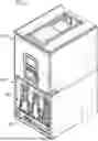
FIG. 1 shows a perspective view of an air conditioning system, in accordance with one or more embodiments of the disclosure.
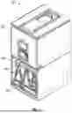
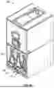
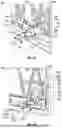
FIG. 2A shows an air conditioning system including a mounted A2L sensor, in accordance with one or more embodiments of the disclosure.
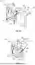
FIG. 2B shows a close-up exploded view of the A2L sensor and a mounting bracket used to hold the A2L sensor, in accordance with one or more embodiments of the disclosure.
FIG. 2C shows the A2L sensor mounted to the mounting bracket of FIG. 2B, in accordance with one or more embodiments of the disclosure.
FIGS. 2D-2E show different perspective views of the A2L sensor and mounting bracket mounting to the air conditioning system of FIG. 2A, in accordance with one or more embodiments of the disclosure.
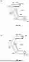
FIGS. 3A-3B show another exemplary mounting bracket for an A2L sensor, in accordance with one or more embodiments of the disclosure.
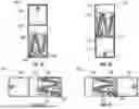
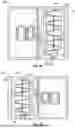
FIGS. 3C-3F show exemplary sensor positioning in various air conditioning system configurations, in accordance with one or more embodiments of the disclosure.
FIG. 3G shows the mounting bracket of FIGS. 3A-3B without a mounting flange, in accordance with one or more embodiments of the disclosure.
FIGS. 4A-4B show other mounting brackets for an A2L sensor, in accordance with one or more embodiments of the disclosure.
FIGS. 4C-4D show the mounting brackets of FIGS. 4A-4B mounted in an air conditioning system, in accordance with one or more embodiments of the disclosure.
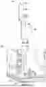
FIG. 5A shows another mounting bracket for an A2L sensor, in accordance with one or more embodiments of the disclosure, in accordance with one or more embodiments of the disclosure.
FIG. 5B shows the mounting bracket of FIG. 5A mounted in an air conditioning system, in accordance with one or more embodiments of the disclosure.
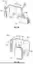
FIG. 6 shows another mounting location for an A2L sensor, in accordance with one or more embodiments of the disclosure.
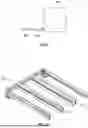
FIGS. 7A-7C show a modified drain pan of an air conditioning system, in accordance with one or more embodiments of the disclosure.
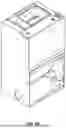
FIG. 8 shows an air conditioning system including a leaked refrigerant pump, in accordance with one or more embodiments of the disclosure.
FIGS. 9A-9B show an air conditioning system with an indicator light, in accordance with one or more embodiments of the disclosure.
DETAILED DESCRIPTION
Disclosed herein are refrigerant sensor mounting mechanisms. Particularly, the mounting mechanisms are constructed such that the refrigerant sensors may be mounted at optimal locations within various types of vapor compression cycle systems (depending on the configuration of the vapor compression cycle system). By positioning the refrigerant sensors in these optimal locations, the sensors can effectively detect any refrigerant leaks that may occur within the vapor compression cycle system within a satisfactory amount of time according to relevant regulations.
A “vapor compression system” may broadly encompass any system that is configured to heat and/or cool a conditioned space, heat and/or cool a fluid that is provided to a load, and/or perform any other actions associated with a vapor compression cycle. Non-limiting examples of types of vapor compression systems can include air conditioners (e.g., no reversing valve, only provides cooling mode), heat pumps (e.g., air source or geothermal; has a reversing valve and operates in both heating and cooling modes), heat pump water heaters, integrated heat pump water heaters, split system heat pump water heaters, heat pump water heaters with a circulation pump and a brazed plate heat exchanger, split systems, packaged systems, mini-splits, PTACs, window units, vertical packaged systems, VRF systems, etc. Reference may be made herein to “air conditioning systems” (or the like), however, this is not intended to be limiting and any other type of vapor compression cycle system may be applicable.
For example, a vapor compression system may generally include components that combine to form a refrigerant loop that is used to produce conditioned air that is circulated throughout the conditioned space by the vapor compression system. For example, the refrigerant loop may include an indoor heat exchanger coil, an outdoor heat exchanger coil, a compressor, and an expansion valve (however, these components may vary, depending on the specific vapor compression system).
Continuing this example, during the operation of this exemplary vapor compression system in a cooling mode, warm indoor air is pulled (or pushed) over the indoor heat exchanger coil (which may be the evaporator coil of the vapor compression system) by a fan of the vapor compression system. As the liquid refrigerant inside the indoor heat exchanger coil converts to gas, heat is absorbed from the indoor air into the refrigerant, thus cooling the air that is pulled over the indoor heat exchanger coil. The fan is then operated to pull the cooled air into a conditioned space (such as a residential home or commercial establishment) that is being cooled by the air conditioning system. In some instances, this cooled air may be distributed throughout the conditioned space using ductwork installed within the conditioned space. The refrigerant gas then passes into the compressor. The compressor pressurizes the refrigerant gas and sends the refrigerant into the outdoor heat exchanger coil, which may operate as a condenser coil. A fan pulls outdoor air through the outdoor heat exchanger coil, allowing the air to absorb heating energy from the home and release it outside. During this process, the refrigerant is converted back to a liquid. The refrigerant then travels back to the indoor heat exchanger coil. The refrigerant passes through an expansion valve, which regulates the flow of refrigerant into the indoor heat exchanger coil. The cold refrigerant then absorbs more heat from the indoor air and the cycle repeats.
Likewise, in a standard heating mode, a reversing valve may be transitioned to direct refrigerant from the compressor to the indoor heat exchanger coil as opposed to directing it to the outdoor heat exchanger coil, as is done in the cooling mode. In a heating mode, the refrigerant absorbs heat from the outdoor air through the outdoor heat exchanger coil. The refrigerant then passes through the compressor, which compresses (and thus warms) the refrigerant. The heated refrigerant is transferred to the indoor heat exchanger coil. One or more fans push or pull air over the indoor heat exchanger coil, thereby transferring heat from the indoor heat exchanger coil to the conditioned space. Ductwork then directs the conditioned air throughout the conditioned space to heat the conditioned space. One or more supplemental heating sources, such as an electric heating kit, and/or a gas furnace with a heat exchanger in the indoor coil portion, may additionally be used. This description is merely exemplary and the specific operation of the vapor compression system may vary depending on the specific vapor compression system.
UL 60335-2-40 is one of many safety standards for household and similar electrical appliances. UL 60335-2-40 outlines various safety requirements, including protections against electric shock, fire hazards, and mechanical hazards. The standard also covers requirements for marking, instructions for use, and testing procedures to ensure compliance with the safety requirements.
Specifically, the standard requires that refrigerant sensors be provided proximate to potential leak points such that refrigerant leaks may be detected and addressed. If a refrigerant leak is detected, the data from the sensor should cause the refrigerant system to shut down. Additionally, the blower should be energized to dilute the refrigerant to reduce the likelihood that the refrigerant reaches a point of ignition.
Potential leak points are defined in Annex FF.1DV of standard UL 60335-2-40 as follows: “[p]iping is not considered to be potential leak points within the area of the appliance to be evaluated if it complies with all of the following: (1) is protected from potential damage during normal operation, service and maintenance; (2) has no connecting joints; and (3) has no bends with centreline bend radius less than 2.5 times the external pipe diameter.” Most conventional air conditioning systems do not comply with at least the centerline bend radius of 2.5 times the external pipe diameter.
As illustrated through UL 60335-2-40, regulations are increasingly requiring not only that refrigerant sensors are provided within the air conditioning systems to detect such refrigerant leaks, but also that the sensors can detect the leaks within a threshold amount of time after a leak initially occurs (defined by Annex MM of the UL 60335-2-40 standard). Therefore, it is often not sufficient that a refrigerant sensor is simply provided in an air conditioning system. It is also important that the refrigerant sensor is positioned such that any leaked refrigerant may be sensed in the amount of time defined by the UL 60335-2-40 standard.
Accordingly, the air conditioning systems described herein are equipped with a refrigerant sensor that is positioned at the bottom portion of a coil compartment of the air conditioning system (an example is illustrated in FIG. 2A) such that the refrigerant sensors are proximate to the drain pan of the air conditioning systems. For example, the refrigerant sensor may be positioned an inch or less above the top of the drain pan (however, this is not intended to be limiting and the refrigerant sensor may also be positioned at other heights depending on the detection range of the specific refrigerant sensor, as well as other factors). By positioning the refrigerant sensor at this location, the refrigerant sensors are more likely to not only detect a refrigerant leak, but also detect the refrigerant leak quickly, as the leaked refrigerant is likely to settle at this location at the bottom of the air conditioning system.
However, air conditioning system and sensor size constraints present challenges with respect to the optimal positioning of the refrigerant sensor. For example, available space for the sensor placement may be limited given the size of the heat exchanger coil within the system. Mounting the sensor directly to the coil can pose issues with the wiring near or in the drain pan.
Accordingly, described herein are various examples of mounting locations and mechanisms (for example, mounting brackets) for mounting the refrigerant sensors at these optimal mounting locations. Specifically, the mounting mechanisms described herein allow for the refrigerant sensors to be mounted as close to the drain pan as possible while also protecting the refrigerant sensors from condensation that is produced by the heat exchanger.
In addition to providing mechanisms that allow for the sensor to be mounted proximate to the bottom of the coil compartment, the air conditioning systems described herein may also include modified drain pans to further assist in the detection of refrigerant leaks. For example, as is shown in FIGS. 7A-7C, one or more troughs may be provided at the drain pan. The troughs may allow for the drain pan to be deepened to increase the flow rate of refrigerant through the drain pan toward the refrigerant sensor. The increased flow rate of refrigerant across the drain pan allows the refrigerant to reach the detection zone of the refrigerant sensor in a shorter amount of time, thereby allowing the sensor to detect the leaked refrigerant in a shorter amount of time.
One common type of refrigerant that is used in conventional air conditioning systems is A2L. Accordingly, reference may be made herein in some instances to an A2L sensor. However, this is not intended to be limiting and any other type of refrigerant sensor may also be used depending on the type of refrigerant that is used in the air conditioning system. Additionally, while reference is made herein in some instances to a single refrigerant sensor, this is also not intended to be limiting and multiple refrigerant sensors may be provided at various locations in the air conditioning system (and vice versa).
FIG. 1 is a perspective view of a partially disassembled exemplary air conditioning system 100. That is, a sidewall of the air conditioning system 100 is shown as being removed such that some of the internal components of the air conditioning system 100 are visible. However, when the air conditioning system is fully assembled, the sidewall may be provided around the internal components to form an enclosure around the internal components as is standard in air conditioning systems.
The specific configuration of the air conditioning system 100 is not intended to be limiting but is rather merely intended to illustrate some of the components of an exemplary air conditioning system 100, as well as to provide a general illustration of the exemplary operation of an air conditioning system 100 (including the use of the refrigerant that is the subject of the refrigerant leak detection described herein). As non-limiting examples of other types of configurations, FIGS. 3C-3F show that the condenser and/or evaporator portions may be provided in different arrangements depending on whether the air conditioning system is an upflow system, a downflow system, a horizontal system, etc. Any reference to a condenser or evaporator portion of an air conditioning system is not intended to be limiting. For example, reference to a particular mounting bracket and/or A2L sensor being provided in an evaporator portion of an air conditioning system may similarly be provided in a condenser portion (and vice versa).
The air conditioning system 100 is shown as a single-package air conditioning system in which a condenser portion 102 and an evaporator portion 104 are both provided within a single package. However, as previously indicated, other types of air conditioning systems may also be applicable, such as air conditioning systems in which the condenser and evaporator are provided as physically separate units (such as in residential settings).
The condenser portion 102 may include at least a condenser coil, a compressor (not shown in the perspective of FIG. 1), and any other components included in conventional air conditioning systems depending on the particular type of air conditioning system. Depending on the configuration, a condenser fan (or fans) may be provided to pull air across the condenser coil and through the condenser portion 102 of the air conditioning system 100 as a part of the refrigerant cycle (described in further detail below). The evaporator portion 104 may include an evaporator coil 106.
In an example embodiment, the air conditioning system 100 may also include a drain pan 108 disposed below and configured to catch or otherwise receive condensate falling from evaporator coil 106. Additionally, air conditioning system 100 may include a drainage pipe to translate the condensate from drain pan 108 to a drain. The air conditioning system 100 may be disposed, for example, on a platform disposed at a predetermined position at the building serviced by the air conditioning system for the purpose of supporting the system. A drain may be provided through the center of the platform, leading to a conduit for delivering condensate to a remote location. In such instances, it may be desirable that drain pan 108 communicates with such a center drain so that condensate from drain pan 108 can be dispensed through the drain. Other drain configurations are also possible.
In an embodiment, the air conditioning system 100 can be used to cool air via a refrigeration cycle that uses a closed-loop refrigerant path. Referring to FIG. 1, the refrigerant path comprises a refrigerant conduit transferring refrigerant from the compressor to the condenser coil, from the condenser coil to an expansion valve, from the expansion valve to the evaporator coil 106, and then back to the compressor. From the compressor, the compressed refrigerant passes through a condenser coil, transferring heat to air moving across the condenser coil in response to condenser fans. Condensed refrigerant from the condenser coil then passes through an expansion valve, lowering the refrigerant's pressure. The refrigerant from the expansion valve then passes through evaporator coil 106 and returns to the compressor.
An evaporator fan pulls air over evaporator coil 106, thereby transferring heat from the air to the refrigerant (and thus cooling the air). The ductwork then directs the cooled air from evaporator fan to a conditioned space. Return ductwork brings air from the conditioned space to evaporator fan, so that evaporator fan, the conditioned space, and the ductwork from a recirculating air path. The evaporator may be disposed either upstream or downstream of evaporator fan so that the refrigerant flowing through evaporator coil 106 draws heat from the traversing air. Condenser fans pull air ambient to air conditioning system 100 (i.e. ambient air) across the condenser coil so that the traversing air removes heat from the refrigerant flowing through the condenser. That is, there is a heat transfer from the refrigerant in the condenser to the air passing across the condenser coil.
Typically, condenser fans and the condenser coil are disposed externally of the space that is to be conditioned (e.g., placed on a roof or otherwise outside of a building for conditioning air within the building). The refrigeration cycle may be reversed in order to operate the system as a heat pump, wherein air is heated and then distributed to the conditioned space. In general, in such an embodiment, the refrigerant circuit includes a three-way (at least) reversing valve between the compressor, on the one hand, and the condenser and the evaporator, on the other, so that the reversing valve controls the directions of refrigerant flow into and out of the compressor. That is, as indicated above, in an air cooling mode, the reversing valve is configured to direct refrigerant from the compressor's output to the condenser's input and to direct refrigerant from the evaporator's output to the compressor's input.
In an air heating mode, the flow of the refrigerant is reversed. The reversing valve switches, so that the valve directs hot refrigerant from the compressor's output to evaporator coil 106, i.e. the coil across which air passes before being distributed to the conditioned space (“indoor coil”), so that evaporator coil 106 operates as a condenser, contributing heat to the air being directed to the conditioned space. The refrigerant circuit (in response to pressure applied by the compressor to the closed refrigerant circuit) directs refrigerant from evaporator coil 106 to an expansion valve, which reduces the refrigerant's pressure, and then to the coil across which fans move ambient air (“outdoor coil”), drawing heat from the ambient air into the refrigerant as it changes state to a gas. The reversing valve receives the refrigerant flow from this coil's output and directs the refrigerant to the compressor, and the cycle repeats. Thus, the roles of the coils are reversed; the evaporator coil in air-cooling mode becomes the condenser coil in air-heating mode; and the condenser coil in air-cooling mode becomes the evaporator coil in air-heating mode.
The air conditioning system may include a controller configured to actuate and de-actuate the compressor and the fans. The controller determines this actuation based on one or more conditions, such as, for example, an air temperature measured by a thermostat located in the conditioned space and in communication with the controller that indicates that the space needs conditioned air (e.g., a temperature sensor in the thermostat senses that temperature of air in a room rises above a predetermined threshold temperature, triggering the thermostat to send a signal to the controller indicating to the controller that the room needs a supply of cold, conditioned air). In this embodiment, the controller, and in particular computer software instructions residing on a memory or other computer-readable medium so that the controller executes actions as dictated by the program instructions, is configured to actuate the reversing valve to switch the closed refrigerant loop and the air conditioning system between an air-cooling mode and an air-heating mode.
Air passing across the coil that acts as an evaporator coil during the air cooling cycle, or, put another way, the coil disposed within the recirculating airflow to and from the conditioned space, is typically filtered to remove dust and dirt particles. In an embodiment, a filter is placed on an intake side of the air conditioning system so that air flows through the filter before passing over this “indoor” coil. As used herein, the term “indoor” coil refers to the coil used for heat transfer with the recirculatory air stream that moves air to and from the indoor conditioned space, regardless of the coil's physical location. That is, the “indoor” coil is the coil in the recirculatory air stream that serves (typically indoor) conditioned space, regardless of whether the coil itself is indoors or out.
FIG. 2A shows an air conditioning system 200 including an A2L sensor 210 to detect any refrigerant leaks from a heat exchanger 206 (or any other component) of the air conditioning system 200. In the example shown, the heat exchanger 206 may be an indoor coil positioned inside a structure or in fluid communication with the structure for conditioning the air therein. As shown in FIG. 2A, the A2L sensor 210 may be mounted at a bottom portion 212 of the heat exchanger 206 so that the sensing element of the A2L sensor 210 is positioned proximate to the drain pan 208. The A2L sensor 210 may also be specifically oriented such that the sensing element of the A2L sensor 210 is pointed downward towards the drain pan 208.
As previously indicated, currently regulations push for the A2L sensor being able to detect a refrigerant leak quickly. Therefore, the positioning of the A2L sensor 210 at the bottom portion 212 of the heat exchanger 206 is not merely a design choice but facilitates the A2L sensor 210 to more quickly detect a refrigerant leak. The A2L sensor 210 is more likely to quickly detect a refrigerant leak when provided in this position given that leaked refrigerant is likely to settle in the drain pan 208. Reference to the A2L sensor 210 being mounted at the bottom portion 212 of the heat exchanger 206 does not necessarily mean that the A2L sensor 210 is positioned entirely beneath the heat exchanger 206. Rather, in some instances, the A2L sensor 210 may simply be mounted closer to the bottom of the heat exchanger 206 than the top of the heat exchanger 206 such that the A2L sensor is positioned proximate to the drain pan 208 where any leaked refrigerant is likely to accumulate.
FIG. 2B shows a close-up view exploded view of the A2L sensor 210 and the mounting bracket 216 that is used to hold the A2L sensor 210 (without the A2L sensor 210 being mounted to the mounting bracket 216). FIG. 2C shows the A2L sensor 210 mounted to the mounting bracket 216 of FIG. 2B. Particularly, the mounting bracket 216 is a “cassette” style mounting bracket. That is, the mounting bracket 216 may include a first portion 240 and a second portion 242 that is provided perpendicularly to the first portion 240.
The mounting bracket 216 may also include a shroud 218. For example, the shroud 218 may be a portion of the mounting bracket 216 that extends from the first portion 240 of the mounting bracket 216 and at least partially envelopes the A2L sensor 210 (without inhibiting the sensing element of the A2L sensor 210). The shroud 218 may be provided to deflect condensation produced by the air conditioning system. This prevents the A2L sensor 210 from being contaminated and/or otherwise damaged by any condensate that may be produced by the heat exchanger 206 during the refrigerant cycle (for example, the heat exchanger may be the evaporator coil 106 described with respect to FIG. 1). That is, the shroud 218 allows the A2L sensor 210 to be positioned at the bottom of the heat exchanger 206 and proximate to the drain pan 208 to effectively detect refrigerant leaks while also mitigating the impact of any condensate that is produced by the heat exchanger 206 and also falls toward the drain pan 208.
The mounting bracket 216 may also include a wire routing hole 219 such that when the mounting bracket 216 is removed from the heat exchanger 208, the mounting bracket 216, the A2L sensor 210, and wires (not shown in the figure) may be removed as one piece.
The mounting bracket 216 may also include one or more fastener apertures. In some embodiments, the mounting bracket 216 may include a first set of fastener apertures (for example, fastener aperture 220, fastener aperture 222, and fastener aperture 224, etc.) provided on the second portion 242 of the mounting bracket 216 that are configured to receive fasteners for securing the mounting bracket 216 to the air conditioning system 200 (shown in FIGS. 2D-2E).
The mounting bracket 216 may also include a second set of apertures (for example, fastener aperture 226, etc.) provided on the first portion 240 of the mounting bracket 216 configured to receive fasteners for securing the A2L sensor 210 to the mounting bracket 216. Likewise, housing 211 of the A2L sensor 210 may include a member 213 including another fastener aperture 215. The fastener aperture 215 on the housing 211 of the A2L sensor 210 may align with the fastener aperture 226 on the mounting bracket 216 such that the A2L sensor 210 may be secured to the mounting bracket 216 when a fastener 217 is provided through both the fastener aperture 215 and the fastener aperture 226.
Although a specific number of fastener apertures are shown as being provided on the mounting bracket 216, this number is merely exemplary and any other number of fastener apertures may also be provided. Additionally, the fastener apertures may be provided at any other positions on the mounting bracket 216 and may be any other size and/or shape as well. Further, the A2L sensor 210 may be secured to the mounting bracket 216 using any other suitable mechanism, such as an adhesive, any other type of structure, etc.
FIGS. 2D-2E show different perspective views of the A2L sensor 210 and the mounting bracket 216 being mounted to the air conditioning system 200 of FIG. 2A. FIGS. 2D-2E show the A2L sensor 210 already mounted to the mounting bracket 216 (for example, in a manner shown in FIG. 2C). In the specific air conditioning system 200 shown in FIGS. 2A-2E, the heat exchanger 206 may include one or more tubes 207 through which the refrigerant flows. Typically, the one or more tubes 207 may be provided through one or more tube sheets 230 to maintain the tubes 207 in place such that the one or more tubes 207 and the one or more tube sheets 230 may form the overall structure of the heat exchanger 206.
To allow the mounting bracket 216 and the A2L sensor 210 to be mounted to the air conditioning system 200, a cutout 232 is provided in a tube sheet 230 of the air conditioning system 200. The cutout 232 is shaped such that the A2L sensor 210 and mounting bracket 216 may be inserted into the hole until the mounting portion 219 of the mounting bracket 216 is flush against the tube sheet 230. Also provided in the tube sheet 230 and proximate to the cutout 232 may be additional fastener apertures (for example, fastener aperture 234, fastener aperture 236, and fastener aperture 238).
The fastener apertures may be positioned on the tube sheet 230 such that they align with the fastener apertures provided in the mounting portion 219 of the mounting bracket 216 when the A2L sensor 210 and mounting bracket 216 are fully inserted into the cutout 232 and the mounting portion 219 of the mounting bracket 216 is flush against the tube sheet 230. In this manner, when the A2L sensor 210 and mounting bracket 216 are fully inserted into the cutout 232, fasteners may be inserted into the fastener apertures on the mounting portion 219 of the mounting bracket 216 and the fastener apertures on the tube sheet 230 to secure the mounting bracket 216 and the A2L sensor 210 to the tube sheet 230. For example, FIGS. 2D-2E show fastener 240 being inserted into fastener apertures 224 and 232, fastener 242 being inserted into fastener apertures 242 and 236, and fastener 244 being inserted into fastener apertures 244 and 238.
Although the mounting bracket 216 and the mounted A2L sensor 210 are shown as being inserted into the cutout 232 in the tube sheet 230 of the heat exchanger 206, this is merely one example of a manner by which the mounting bracket 216 and the mounted A2L sensor 210 may be positioned proximate to the drain pan 208. Other arrangements may also be possible depending on the configuration of the mounting bracket and the air conditioning system in which the A2L sensor is being provided. Further non-limiting examples of brackets that are configured for other types of exemplary air conditioning systems are shown in FIGS. 3A-5B.
FIGS. 3A-3B show another exemplary mounting bracket 316 that may be used to mount an A2L sensor 310 (which may be the same as, or similar to, A2L sensor 210 or any other A2L sensor described herein otherwise). Specifically, the mounting bracket 316 is a multi-position mounting bracket that is configured to mount the A2L sensor 310 horizontally along the top of the drain pan. In this manner, the A2L sensor 310 may be positioned even more proximate to any leaked refrigerant accumulation in the drain pan to allow for quicker detection of refrigerant. Locating the sensor as close to the drain pan as possible and pointing the sensing element towards the coil increases the chance of refrigerant detection and reduces the chance that condensation enters the sensor since the sensor is not mounted directly to the coil. The “L” shape of the piece provides support so that if the back of the mounting bracket 316 is pushed in towards the heat exchanger, the A2L sensor 310 may be prevented from contacting any element of the heat exchanger to reduce the potential for damage.
As shown in FIGS. 3A-3B, the mounting bracket 316 includes a first portion 302 and a second portion 304 positioned perpendicular to each other. The first portion 302 may include one or more fastener apertures (for example, fastener aperture 305, fastener aperture 306, fastener aperture 307) that are configured to receive fasteners to secure the A2L sensor 310 to the mounting bracket 316. The fastener apertures may be positioned at various locations on the first portion 302 of the mounting bracket 316 to allow the A2L sensor 310 to be mounted on the mounting bracket 316 in different orientations. For example, FIG. 3A shows the A2L sensor 310 being mounted to the mounting bracket 316 in a horizontal orientation and FIG. 3B shows the A2L sensor 310 being mounted to the mounting bracket 316 in a vertical orientation. Mounting the A2L sensor 310 in different orientations allows for the A2L sensor 310 to be kept parallel to the drain pan when the system is installed in the field in other orientations depending how the ductwork in the conditioned space is configured.
Particularly, the fastener apertures provided on the first portion 302 of the mounting bracket 316 may be arranged to align with one or more fastener apertures provided on the housing of the A2L sensor 310. For example, the specific A2L sensor 310 shown in FIGS. 3A-3B includes members 314 and 316 that extrude from the sensor housing, with member 314 including fastener aperture 315 and member 316 including fastener aperture 317. Fasteners may either be provided through both of the fastener apertures 315 and 317 and corresponding fastener apertures on the first portion 302 of the mounting bracket 316, or may be provided through one of the fastener apertures 315 and 317 and a corresponding fastener aperture on the mounting bracket 316. The specific fastener apertures on the mounting bracket 316 that are used may depend on the orientation of the A2L sensor 310. Additionally, to accommodate the member 316 when the A2L sensor 310 is in the horizontal orientation shown in FIG. 3A, a cutout 312 may be provided in the second portion 304 of the mounting bracket 316.
FIGS. 3C-3F show exemplary sensor positioning in various air conditioning system configurations. Beginning with FIG. 3C, an example of an upflow air conditioning system 300 is shown. Generally, an upflow air conditioning system receives intake air through the bottom of the air conditioning system and expels air into the home (assuming the air conditioning system is provided in a residential home in this example) out of the top of the air conditioning system. For example, in residential settings, upflow air conditioning systems are typically provided in a basement (or low point in the home). Given that hot air rises and cool air sinks, having an air conditioning system on the bottom floor allows the air conditioning system to take in more cold air to convert into warmer air to provide to the home.
Accordingly, the air conditioning system 300 in the upflow configuration includes a burner chamber 304 that is provided below a blower chamber 302. Airflow is directed from a blower in the blower chamber 302 down into the burner chamber 304, which includes the heat exchanger 306. As another example of an A2L sensor mounting position, rather than the A2L sensor 310 being positioned at a bottom portion of the heat exchanger 306 proximate to the drain pan 308, the mounting bracket may instead be mounted directly to a top portion of the drain pan such that the A2L sensor is positioned even closer to any leaked refrigerant accumulation in the drain pan.
FIG. 3D shows a downflow air conditioning system 310. Generally, a downflow air conditioning system operates in the opposite manner as the upflow air conditioning system. That is, the downflow air conditioning system receives intake air through the top of the air conditioning system and expels air into the home (assuming the air conditioning system is provided in a residential home in this example) out of the bottom of the air conditioning system. For example, in residential settings, downflow air conditioning systems are typically provided in an attic (or high point in the home).
Accordingly, the air conditioning system 310 in the downflow configuration includes a burner chamber 314 that is provided above a blower chamber 312. Airflow is directed from a blower in the blower chamber 312 up into the burner chamber 314, which includes the heat exchanger 316.
FIGS. 3E-3F show horizontal air conditioning systems 320 and 330. In contrast with air conditioning systems 300 and 310, in which the burner and blower chambers are provided on top of one another, the horizontal air conditioning systems 320 and 330 provide the burner and blower chambers in a side-by-side arrangement. FIG. 3E shows one example air conditioning system 320 configuration in which the blower chamber 322 is located to the left of the burner chamber 324 (which includes heat exchanger 326 and drain pan 329). FIG. 3F shows another example air conditioning system 330 configuration in which the blower chamber 332 is located to the right of the burner chamber 334 (which includes heat exchanger 336 and drain pan 339). In both configurations, the A2L sensors 328 and 338 are provided at the bottom of the heat exchangers and proximate to the drain pans. FIG. 3G shows the mounting bracket of FIGS. 3A-3B without a mounting flange.
FIGS. 4A-4B show further examples of mounting brackets 400 (FIG. 4A) and 420 (FIG. 4B) for an A2L sensor 410. The mounting brackets 400 and 420 are constructed such that the A2L sensor 460 is pointed towards the heat exchangers of the air conditioning systems. The specific configurations shown in FIGS. 4A-4B are merely exemplary and other configurations may also be possible.
Beginning with FIG. 4A, the mounting bracket 400 includes a first portion 402 and a second portion 404 that are both connected to a third portion 406. The first portion 402, second portion 404, and third portion 406 are arranged such that the A2L sensor 460 may be secured to the mounting bracket 400 within a void 407 formed by the first portion 402, second portion 404, and third portion 406. For example, the first portion 402 and second portion 404 are shown as being perpendicular to the third portion 406 and the first portion 402 and second portion 404 are also shown as being perpendicular to one another.
To allow for the mounting bracket 400 to be secured to the air conditioning system 440 or 450 (for example, to a tube sheet of the air conditioning system 440 or 450 (or any other portion of the air conditioning system 440 or 450), a first member 408 including a fastener aperture 409 extends perpendicularly from the first portion 402, and a second member 410 including a fastener aperture 411 extends perpendicularly from the second portion 404. When the mounting bracket 400 is installed in the air conditioning system 440 or 450, the first member 408 and the second member 410 are provided flush against the tube sheet. The tube sheet may also include fastener apertures that are positioned such that they align with the fastener apertures 409 and 411 when the mounting bracket 400 is properly aligned at the tube sheet. Fasteners may then be inserted through the fastener apertures 409 and 411 and the corresponding fastener apertures on the tube sheet to secure the mounting bracket 400 to the tube sheet.
To allow for the A2L sensor to be secured to the mounting bracket 400, the third portion 406 may also include fastener apertures (for example, fastener aperture 412 and fastener aperture 415. In some embodiments, fastener aperture 415 may be provided in third member 414 that extends from the third portion 406. The A2L sensor may include corresponding fastener apertures such that fasteners may be inserted into fastener apertures 412 and 415, as well as corresponding fastener apertures on the A2L sensor, to secure the A2L sensor to the mounting bracket 400. The number and positioning of the fastener apertures for securing the A2L sensor to the mounting bracket 400 and for securing the mounting bracket 400 to the air conditioning system 440 or 450 are merely exemplary and may vary depending on the application.
FIG. 4B shows a different configuration for a mounting bracket 420. The mounting bracket 420 includes a similar structure as the mounting bracket 400 of FIG. 4A, however, is configured for an upflow orientation air conditioning system, whereas the mounting bracket 400 is configured for a horizontal installation.
FIGS. 4C-4D show exemplary air conditioning systems 440 (FIG. 4C) and 450 (FIG. 4D) including the mounting brackets of FIGS. 4A-4B. Specifically, the air conditioning systems 440 and 450 are shown as horizontal air conditioning systems. Each of the air conditioning systems 440 and 450 includes a heat exchanger 442 including coils 444 that are provided through a tube sheet 446. The air conditioning system 440 and 450 also include a drain pan 448.
Similar to the air conditioning systems 200, 300, 310, 320, and 330 shown in FIGS. 2A, and 3C-3F, the air conditioning systems 440 and 450 shown in FIGS. 4C-4D include the mounting brackets 400 or 410 provided at a bottom portion of the heat exchanger 442 proximate to a top portion of the drain pan 448. However, in contrast with the air conditioning systems 200, 300, 310, 320, and 330, the A2L sensor 449 in the air conditioning systems 440 and 450 is shown as being pointed towards the heat exchanger 442.
FIG. 5A shows another mounting bracket 516 for an A2L sensor 510 (shown in FIG. 5B). The A2L sensor 510 may be the same as, or similar to, A2L sensors 210, 310, and/or any other A2L sensor described herein or otherwise. When the air conditioning system 500 is in the downflow position, locating the A2L sensor 510 into the lower most part of the unit (blower compartment) allows the A2L sensor 510 to detect any refrigerant pooling in the lowest portion of the air conditioning system 500. Also, doing this allows the A2L sensor 510 to detect possible pooling of the refrigerant in a potential ignition source location (e.g., the control box area). FIG. 5B shows the mounting bracket 516 installed in the blower section for downflow to detect leaked refrigerant at the lowest point of the air conditioning system 500.
In embodiments, the mounting bracket 516 includes a first portion 502 and a second portion 504 that are connected by a third portion 506. The first portion 502 and the second portion 504 may be parallel or substantially parallel and the third portion 506 may be perpendicular or substantially perpendicular with the first portion 502 and the second portion 504. Thus, the second portion 504, by nature of its connection with the third portion 506, is located outwards from the first portion 502 when the mounting bracket 516 is mounted in the air conditioning system 500 (shown in FIG. 5B).
The mounting bracket 516 also includes one or more fastener apertures for securing the mounting bracket 516 to the air conditioning system 500 and for securing the A2L sensor 510 to the mounting bracket 516. For example, the first portion 502 of the mounting bracket 516 is shown as including fastener aperture 518 and fastener aperture 520. Although not shown in FIGS. 5A-5B, the air conditioning system may include corresponding fastener apertures in a tube sheet 530 of the air conditioning system 500. The fastener apertures of the tube sheet 530 and the fastener aperture 518 and fastener aperture 520 may be configured to receive fasteners such that the bracket 516 may then be mounted to the tube sheet 530 (as is shown in FIG. 5B). In some embodiments, the mounting bracket 516 may be mounted to the blower housing of the air conditioning system 500. In the downflow position, the blower compartment may be positioned to the bottom of the air conditioning system 500. This mounting location may allow for easier detection of refrigerant because the refrigerant naturally migrates to the bottom of the unit. Another potential reason is that mounting the mounting bracket 516 in this area can detect leaked refrigerant around spark ignition components. However, other mounting locations are also possible.
Similar to other A2L sensors described herein, the housing 511 of the A2L sensor 510 may include first member 532 and second member 534. The first member 532 may include fastener aperture 533 and the second member 534 may include fastener aperture 535. To mount the A2L sensor 510 to the mounting bracket 516, fasteners may be provided through the fastener aperture 533 of the housing 511 of the A2L sensor 510 and fastener aperture 522 of the mounting bracket 516, and fastener aperture 535 of the housing 511 of the A2L sensor 510 and fastener aperture 524 of the mounting bracket 516.
FIG. 6 shows another mounting location for an A2L sensor. Externally mounting the A2L sensor in the condensate drain allows the A2L sensor to be at the lowest point of the air conditioning system regardless of the position of the air conditioning system if installed correctly and above the water line within the drain. Inserting the A2L sensor in a “T” on the drain line just outside of the air conditioning system may trip the A2L sensor when the refrigerant concentration reached the point of the A2L sensor % LFL setpoint. Similarly, rather than using the “T”, a housing that accommodates the A2L sensor may be installed.
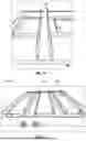
FIGS. 7A-7C show a modified drain pan 700 of an air conditioning system. As previously indicated, in addition to providing mechanisms that allow for the A2L sensor to be mounted proximate to the bottom of the coil compartment (for example, the mounting brackets shown in FIGS. 2A-5B), the air conditioning systems described herein may also include modified drain pans to further assist in the detection of refrigerant leaks.
Specifically, the depth of the modified drain pan 700 may be greater than a conventional drain pan. For example, the depth increase may be 0.250″, 0.500″, 0.750″, and 1.000″, or any other depth increase. to allow a higher flow rate of any refrigerant that is being leaked. The higher flow rate of the leaked refrigerant increases the chance that the A2L sensor can detect the leaked refrigerant. That is, the design of the modified drain pan 700 more quickly directs the leaked refrigerant towards the front of the coil where the A2L sensor may be positioned.
The modified drain pan 700 may also include troughs (for example, trough 702, trough 704, and/or any other number of troughs) to the bottom of the drain pan 700 to increase the wall height to allow a higher flow of refrigerant that is being leaked at the back of the coil and flow to the front of the coil. In some embodiments, rather than deepening the drain pan, the configuration shown in FIGS. 7A-7C may “clip” or otherwise attach to the bottom of an existing drain pan to increase the overall height of the existing drain pan. This allows for easy installation for manufacturing and does not require added mounting constraints.
FIG. 7B shows another example of a trough 702 that has not yet been installed in a drain pan. FIG. 7C shows trough 702 and trough 704 installed in drain pan 700. Other exemplary modifications may include separate veins that are more specific to just the leaked refrigerant and/or widening the drain pan to provide for more leaked refrigerant flow.
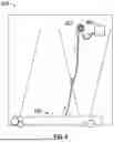
FIG. 8 shows an air conditioning system 800 including a leaked refrigerant pump 802. The air conditioning system 800 includes of a pump 802 to draw leaked refrigerant to the sensor 804. By using the pump 802 to draw leaked refrigerant, the sensor may be provided further away from the condensation that may be produced by the air conditioning system 800 and may greatly reduce the chances of the sensor failure that can be caused by moisture. In tight fitments where sensors cannot be easily installed, the hose for the pump 802 may be placed in a more precise location to ensure the leaked refrigerant is detected. In some instances, several hoses may also be tied together and placed at different locations so refrigerant can be detected refrigerant from all corners of the air conditioning system 800 to ensure the best chance of leaked refrigerant from anywhere in the conditioning system 800. The pump 802 may be integrated with the sensor 804 as well.
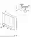
FIGS. 9A-9B show an air conditioning system 900 with an indicator light 902. The air conditioning system 900 may be the same as, or similar to, any of the other air conditioning systems described herein or otherwise. The indicator light 902 may be configured to provide information about data captured by the A2L sensor 904 (which may be the same as, or similar to, any A2L sensor described herein or otherwise). For example, the indicator light 902 may be configured to illuminate when the A2L sensor 904 indicates that a refrigerant leak has been detected in the air conditioning system 900. The indicator light may be any type of light that is capable of illuminating (such as a light-emitting diode (LED) or any other type of illuminating element). FIGS. 9A-9B show that the indicator light 902 for the A2L sensor 904 does not necessarily need to be directly affixed to the A2L sensor 904 (or sensor housing) itself, but rather may be provided at a separate location that is more readily viewable and/or accessible by a technician (or other type of user).
Beginning with FIG. 9A, a first exemplary embodiment for an air conditioning system 900 with an indicator light 902 is shown. In this first embodiment, the indicator light 902 is added to a wire harness 906 of the air conditioning system 900. The wire harness may be provided within the air conditioning system 900 to facilitate electrical signal transmission between various components of the air conditioning system (such as the A2L sensor 904, controller 908, etc.). The indicator light 902 may be added to the wire harness 906 in this exemplary embodiment by directly wiring the indicator light 902 to the existing wire harness 906, for example.
In some instances, the wire harness 906 may be a non-rigid structure, which provides versatility in the placement of the indicator light 902 on and/or within the air conditioning system 900 (that is, the wire harness 906 may be moved around, such that the indicator light 902 can be placed at various locations on and/or within the air conditioning system 900). In one or more embodiments, the indicator light 902 may be mounted to a wall of the air conditioning system 900. Particularly, the indicator light 902 may be mounted through the wall, such that the indicator light 902 is then visible to a technician from outside of the air conditioning system 900, providing a convenient mechanism for the technician to view information about the data captured by the A2L sensor 904 without disassembling part of the air conditioning system 900 to access the A2L sensor 904.
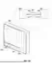
Turning to FIG. 9B, a second exemplary embodiment for an air conditioning system 900 with an indicator light 902 is shown. In this second embodiment, the indicator light 902 is directly affixed (or otherwise integrated into or onto) a connector included in the wire harness 906.
In the exemplary embodiment shown in FIG. 9B, the wire harness 906 includes two connectors (a first connector 910 and second connector 912 that connect at some point along the wire harness 906 between the controller 908 and the A2L sensor 904. That is, in the exemplary embodiment shown in FIG. 9B, the wires of the wire harness are directly connected to the controller 908 and the A2L sensor 904. This allows the connection point at the controller 908 and the A2L sensor 904 to be sealed from liquids to prevent liquid from entering the A2L sensor 902 and damaging the A2L sensor 902. However, it should be noted that this configuration is not intended to be limiting and additional connectors may be provided at the controller 908 and/or the A2L sensor 904 as well.
In this exemplary embodiment, the indicator light 902 is shown as being directly affixed (or otherwise integrated into or onto) the first connector 910. This is merely one exemplary implementation, however, and the indicator light 902 may instead be directly affixed (or otherwise integrated into or onto) the second connector 912. In other embodiments, the indicator light 902 may be directly affixed (or otherwise integrated into or onto) any other connector shown in FIG. 9B, or any other connector not shown in FIG. 9B. That is, the wire harness 906 shown in FIG. 9B is merely one exemplary wire harness and other configurations of wire harnesses may exist. For example, another air conditioning system may include other electrical components, and therefore the wire harness for that air conditioning system may include additional wired connections and connectors. The wire harness 906 may also differ in any other way.
Although FIGS. 9A-9B show one indicator light 902 being provided as a part of the wire harness 906, this is not intended to be limiting and any other number of indicator lights 902 may be provided. If multiple indicator lights 902 are used, the indicator lights 902 may be provided at any number of different positions on and/or within the air conditioning system 900.
It should be apparent that the foregoing relates only to certain embodiments of the present application and that numerous changes and modifications may be made herein by one of ordinary skill in the art without departing from the general spirit and scope of the disclosure.
Although specific embodiments of the disclosure have been described, numerous other modifications and alternative embodiments are within the scope of the disclosure. For example, any of the functionality described with respect to a particular device or component may be performed by another device or component. Further, while specific device characteristics have been described, embodiments of the disclosure may relate to numerous other device characteristics. Further, although embodiments have been described in language specific to structural features and/or methodological acts, it is to be understood that the disclosure is not necessarily limited to the specific features or acts described. Rather, the specific features and acts are disclosed as illustrative forms of implementing the embodiments. Conditional language, such as, among others, “can,” “could,” “might,” or “may,” unless specifically stated otherwise, or otherwise understood within the context as used, is generally intended to convey that certain embodiments could include, while other embodiments may not include, certain features, elements, and/or steps. Thus, such conditional language is not generally intended to imply that features, elements, and/or steps are in any way required for one or more embodiments.
Claims
That which is claimed is:1. An air conditioning system comprising:
a heat exchanger;
a drain pan;
a mounting bracket that is mounted at a bottom portion of the heat exchanger and above a drain pan of the heat exchanger; and
a refrigerant sensor that is mounted to the mounting bracket and configured to detect a refrigerant leak from the heat exchanger.
2. The air conditioning system of claim 1, wherein the mounting bracket includes a first portion and a second portion that is perpendicular to the first portion.
3. The air conditioning system of claim 2, wherein the first portion includes one or more first apertures for receiving one or more first fasteners to fasten the mounting bracket to the air conditioning system, and wherein the second portion includes one or more second apertures for receiving one or more second fasteners to fasten the refrigerant sensor to the mounting bracket.
4. The air conditioning system of claim 3, wherein the one or more first fasteners are arranged to receive the refrigerant sensor in either a horizontal or vertical orientation.
5. The air conditioning system of claim 2, wherein the first portion of the mounting bracket includes a wire routing hole.
6. The air conditioning system of claim 1, wherein the mounting bracket includes a shroud to protect the refrigerant sensor from condensation produced by the heat exchanger.
7. The air conditioning system of claim 1, further comprising a cutout in a tube sheet of the heat exchanger, wherein the cutout is shaped to receive the mounting bracket and the refrigerant sensor.
8. The air conditioning system of claim 1, wherein the drain pan includes one or more troughs to direct refrigerant flow to a location of the refrigerant sensor.
9. The air conditioning system of claim 1, wherein the refrigerant sensor is an A2L sensor.
10. The air conditioning system of claim 1, wherein the refrigerant sensor is mounted within an inch of a top of the drain pan.
11. The air conditioning system of claim 1, wherein the mounting bracket includes a first portion, a second portion, and a third portion, wherein the first portion is parallel with the second portion, wherein the third portion is perpendicular with the first portion and second portion, and wherein the third portion connects the first portion and second portion.
12. An air conditioning system comprising:
a heat exchanger;
a drain pan;
a mounting bracket that is mounted at a top portion of the drain pan; and
a refrigerant sensor that is mounted to the mounting bracket and configured to detect a refrigerant leak from the heat exchanger.
13. The air conditioning system of claim 12, wherein the mounting bracket includes a wire routing hole.
14. The air conditioning system of claim 12, wherein the mounting bracket includes a shroud to protect the refrigerant sensor from condensation produced by the heat exchanger.
15. The air conditioning system of claim 12, further comprising a cutout in a tube sheet of the heat exchanger, wherein the cutout is shaped to receive the mounting bracket and the refrigerant sensor.
16. The air conditioning system of claim 12, wherein the drain pan includes one or more troughs to direct refrigerant flow to a location of the refrigerant sensor.
17. The air conditioning system of claim 12, wherein the refrigerant sensor is an A2L sensor.
18. A mounting bracket for a refrigerant sensor of an air conditioning system, the mounting bracket comprising:
a first portion that includes one or more first apertures for receiving one or more first fasteners to fasten the mounting bracket to the air conditioning system; and
a second portion that is perpendicular to the first portion and includes one or more second apertures for receiving one or more second fasteners to fasten a refrigerant sensor to the mounting bracket,
wherein the refrigerant sensor is configured to detect a refrigerant leak from a heat exchanger of the air conditioning system.
19. The mounting bracket of claim 18, wherein the first portion of the mounting bracket includes a wire routing hole.
20. The mounting bracket of claim 18, wherein the mounting bracket includes a shroud to protect the refrigerant sensor from condensation produced by the air conditioning system.
Images & Drawings included:
Sources:
- United States Patent and Trademark Office - verify current appl. status at the USPTO↗
Recent applications in this class:
- » 20260055920 2026-02-26
DEVICE FOR CONTROLLING HEATING VENTILATION AND AIR CONDITIONING (HVAC) SYSTEMS - » 20260055919 2026-02-26
AIRFLOW MEASURING SYSTEM FOR A BUILDING HAVING A SENSOR ASSEMBLY MOUNTED TO A WALL OF AN AIR CONDUIT - » 20260055918 2026-02-26
AIR POLLUTION CLEANING SMART NETWORK MECHANISM SYSTEM FOR CONTROLLING INDOOR AIR TEMPERATURE AND HUMIDITY - » 20260036325 2026-02-05
HUMIDIFIER - » 20260009554 2026-01-08
SYSTEMS AND METHODS FOR WIRELESSLY CONFIGURING CLIMATE CONTROL SYSTEM CONTROLS - » 20250383113 2025-12-18
AIR CLEANER - » 20250341336 2025-11-06
AIR CONDITIONER AND METHOD FOR CONTROLLING SAME - » 20250305709 2025-10-02
THERMOSTAT BACKPLATE - » 20250297766 2025-09-25
Electric Control Box and Air Conditioner - » 20250237405 2025-07-24
ARRANGEMENT FOR REFRIGERANT LEAK MANAGEMENT