TOP TOY COMPONENT AND TOP TOY
US20260097322A1
2026-04-09
19/285,053
2025-07-30
Smart Summary: A top toy has two main parts: a trunk and a shaft. The trunk has a hole where the shaft fits in. The shaft has two sections that allow it to spin. When the trunk and the first section of the shaft rotate, they can change the shape of the trunk's outer edge. This design makes the top toy more fun and interesting to play with. 🚀 TL;DR
Abstract:
A top toy component includes a first trunk part having a hole, and a shaft member having first and second portions. The shaft member is detachably inserted to the hole to rotate around the shaft member. The hole part and the first portion are configured to rotate relatively with respect to the second portion to change an outer circumferential shape of the first trunk part.
Assignee:
- TOMY COMPANY ,LTD. 152 🇯🇵 Tokyo, Japan
Applicant:
Interested in similar patents?
Get notified when new applications in this technology area are published.
Description
CROSS-REFERENCE TO THE RELATED APPLICATION
The present application claims priority under 35 U.S.C. 119 to Japanese Patent Application No. 2024-176940 filed on Oct. 9, 2024. The entire content of Japanese Patent Application No. 2024-176940 is incorporated herein by reference.
BACKGROUND
Technical Field
The present invention relates to a top toy component and a top toy.
Background Art
Conventionally, known is a top toy comprising a top toy body having an insertion hole, and a shaft that can be inserted in and removed from the insertion hole, the top toy having the ability to change the rotation characteristics by exchanging the shaft (see Patent Document 1, for example).
This top toy is used in a battle game in which rotating top toys are collided with each other, for example.
Patent Document 1: Japanese Patent Publication No. 7349003
SUMMARY
Problems the Invention is Intended to Solve
In the abovementioned top toy, the rotation characteristics are changed by exchanging the shaft, but there is demand for a new structure that allows for changing the top toy performance during a battle game.
The purpose of the present invention is to provide a top toy component and a top toy that allows changing of performance during a battle game.
Means for Solving the Problems
A top toy component includes a first trunk part having a hole, and a shaft member having first and second portions. The shaft member is detachably inserted to the hole to rotate around the shaft member. The hole part and the first portion are configured to rotate relatively with respect to the second portion to change an outer circumferential shape of the first trunk part.
BRIEF DESCRIPTION OF THE DRAWINGS
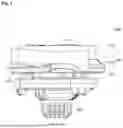
FIG. 1 is a side view of a top toy of a first mode according to the present embodiment.
FIG. 2 is a top view of the top toy of the first mode according to the present embodiment.
FIG. 3 is a side view of the top toy of a second mode according to the present embodiment.
FIG. 4 is a top view of the top toy of the second mode according to the present embodiment.
FIG. 5 is a perspective view showing the disassembled state of the top toy during a top battle.
FIG. 6 is an exploded perspective view of an upper trunk part.
FIG. 7 is a plan view of an upper layer part viewed from below.
FIG. 8 is a plan view of a lower layer part viewed from below.
FIG. 9 is a perspective view of a lower plate viewed from above.
FIG. 10 is a perspective view of the lower plate viewed from below.
FIG. 11 is a plan view of a first state lower layer part and lower plate viewed from above.
FIG. 12 is a plan view of a second state lower layer part and lower plate viewed from above.
FIG. 13 is an exploded perspective view of a lower trunk part assembly.
FIG. 14 is a perspective view of an upper plate.
FIG. 15 is a plan view of the top toy in a state with the upper trunk part and the upper plate removed.
FIG. 16 is a perspective view showing a shaft member and its periphery.
FIG. 17 is a perspective view of the shaft member.
FIG. 18 is a plan view of the lower trunk part assembly viewed from above.
FIG. 19 is a plan view of the lower trunk part assembly viewed from above.
FIG. 20 is a perspective view showing a top shooting device.
FIG. 21 is a perspective view showing the external appearance of a battle stadium.
DETAILED DESCRIPTION OF PREFERRED EMBODIMENTS
FIG. 1 is a side view of a top toy 1000 of a first mode in the present embodiment. FIG. 2 is a top view of the top toy 1000 of the first mode. FIG. 3 is a side view of the top toy 1000 of a second mode. FIG. 4 is a top view of the top toy 1000 of the second mode.
The top toy 1000 is used in a top battle collided with another top toy to fight.
The top toy 1000 comprises a trunk part 100 configured including an upper trunk part 110 (first trunk part) and a lower trunk part assembly 120 (second trunk part), and a rod-shaped shaft member 200. The upper trunk part 110 is included in the top toy components.
The outer circumference shape of the upper trunk part 110 can be changed from the first mode to the second mode during a top battle.
FIG. 5 is a perspective view showing the disassembled state of the top toy 1000 during a top battle.
As shown in FIG. 5, as a result of the top battle, the top toy 1000 can be disassembled into two, the upper trunk part 110, and the lower trunk part assembly 120 and the shaft member 200.
(Top Toy 1000) The top toy 1000 is constituted mostly from plastic, but may also be constituted using other materials.
Upper Trunk Part 110
The upper trunk part 110 rotates centered around the shaft member 200 in a state with the top toy 1000 assembled.
FIG. 6 is an exploded perspective view of the upper trunk part 110.
The upper trunk part 110 comprises an upper layer part 111 (upper layer), a lower layer part 112 (lower layer), and a lower plate 113, and is constituted from a plurality of layers.
Though not particularly limited, the upper layer part 111 is a composite configured by assembling a plurality of components. The upper layer part 111 includes a flywheel made of metal, for example.
On the outer circumference side of the upper layer part 111, upper layer jutting parts 111a that jut facing outward are formed at prescribed intervals at three locations, for example.
On the outer circumference inside of the upper layer part 111, arc-shaped holes 111b are formed at prescribed intervals in three locations in the circumferential direction extending concentrically with the shaft member 200. The number of arc-shaped holes 111b is not limited to being three. These arc-shaped holes 111b are used when rotationally energizing the top toy 1000.
FIG. 7 is a plan view of the upper layer part 111 viewed from below.
On the bottom surface of the upper layer part 111, a female threaded boss 111c in which a male screw 117 described later is screwed is established.
By the lower layer part 112 rotating relatively with respect to the upper layer part 111, the outer circumference shape of the upper trunk part 110 changes.
The lower layer part 112 comprises a cylinder part 114 (hole part) disposed in the center of the lower layer part 112, and an outer circumference 115 constituting the outer circumference of the lower layer part 112, and preferably, further comprises a coupling part 116 for coupling the cylinder part 114 and the outer circumference 115.
FIG. 8 is a plan view of the lower layer part 112 viewed from below.
One end of the shaft member 200 in inserted from below in the interior of the cylinder part 114.
On the inner circumference wall of the cylinder part 114, along from the top end to the bottom end, for example eight convex parts 114a projecting toward the center of the cylinder part 114 are formed at prescribed intervals. The number of convex parts 114a is not limited to being eight. The plurality of convex parts 114a may also be formed not at equal intervals on the inner circumference wall of the cylinder part 114. Engagement parts 20a described later of the shaft member 200 are engaged between the convex parts 114a. In other words, the plurality of convex parts 114a function as the engaged part that transmits the rotational force of the shaft member 200 by engaging with the engagement parts 20a.
The outer circumference wall of the cylinder part 114 has an uneven shape, and by convex parts 116c described later of the coupling part 116 meshing and being in sliding contact with the uneven shape, this can constitute a clutch mechanism. As a result, the cylinder part 114 is held to be able to rotate with respect to the coupling part 116. The clutch mechanism receives the rotational force of the shaft member 200 via the cylinder part 114. The clutch mechanism is not limited to this mode. For example, it is also possible to have the cylinder part 114 and the coupling part 116 be an integrated member, and to be a click mechanism in which the engagement parts 20a of the shaft member 200 and the convex parts 114a surpass each other at a fixed resistance.
On the outer circumference 115, for example three lower layer jutting parts 115a that jut facing outside are formed at prescribed intervals. The plurality of lower layer jutting parts 115a may also not be formed at equal intervals on the outer circumference 115.
The edge of the tip of the lower layer jutting part 115a is an arc shape as one example.
The coupling part 116 comprises a ring-shaped part 116a surrounding the cylinder part 114, and projecting parts 116b (projecting pieces) projecting facing outward from the outer circumference wall of the ring-shaped part 116a.
Each projecting piece 116b can move within a prescribed range which is between two convex parts 113b, 113b described later of the lower plate 113 centered on the shaft member 200.
On the inner circumference wall of the ring-shaped part 116a, three convex parts 116c projecting toward the center of the ring-shaped part 116a are formed at prescribed intervals.
On the outer circumference wall of the ring-shaped part 116a, a second protruding part 116d is formed projecting facing outward.
The projecting parts 116b are formed at three prescribed intervals, for example, and couple the coupling part 116 and the outer circumference 115.
On one of the three projecting parts 116b, a first protruding part 116e that projects from the side surface of the projecting part 116b is formed.
When the cylinder part 114 rotates with respect to the coupling part 116, the outer circumference wall of the cylinder part 114 and the convex parts 116c are susceptible to wear due to friction because they are in sliding contact. For that reason, it is preferable that the cylinder part 114 and the coupling part 116 be formed using a hard material that is wear resistant. The cylinder part 114 and the coupling part 116 do not have to be formed with a hard material.
Meanwhile, the outer circumference 115 is at a site that may collide with other top toys during a battle game, so it is preferable to be formed using a softer material than the cylinder part 114 and the coupling part 116. The outer circumference 115 does not have to be formed using a soft material.
FIG. 9 is a perspective view of the lower plate 113 viewed from above.
An insertion hole 113a in which the cylinder part 114 is inserted is formed at the center of the lower plate 113.
In the lower plate 113, further to the outside than the insertion hole 113a and inside the outer circumference, convex parts 113b projecting upward from the top surface are formed at three prescribed intervals, for example.
At the center of the convex part 113b, a counterbore hole 113c in which the male screw 117 is inserted from below is formed.
A first engagement part 113d is formed on the side surface in the circumferential direction of the convex part 113b.
A second engagement part 113e is formed on the side surface of the center side of the convex part 113b.
FIG. 10 is a perspective view of the lower plate 113 viewed from below.
A butterfly-shaped fitting wall 113f is established on the bottom surface of the lower plate 113 so as to surround the insertion hole 113a. In the fitting wall 113f, at least a portion of the upper plate 14 (see FIG. 13) is fitted. A joining piece 113g used when joining the upper trunk part 110 with the lower trunk part assembly 120 is formed on the outside of this fitting wall 113f.
The lower plate 113 of the present embodiment is for rotating clockwise, but by changing the formation position of the joining piece 113g, can be for rotating counterclockwise.
On the female threaded boss 111c of the upper layer part 111, the male screw 117 is screwed through the counterbore hole 113c of the lower plate 113 in a state with the lower layer part 112 gripped by the upper layer part 111 and the lower plate 113.
First Mode Upper Trunk Part 110
With the upper trunk part 110 of the first mode, as shown in FIG. 1 and FIG. 2, the lower layer jutting parts 115a take positions exposed between adjacent upper layer jutting parts 111a. For that reason, the outer circumference shape of the upper trunk part 110 of the first mode is substantially circular in the plan view.
In the upper trunk part 110 of the first mode, the projecting parts 116b of the coupling part 116 are disposed at positions overlapping the positions between two arc-shaped holes 111b and 111b of the upper layer part 111. Specifically, the projecting parts 116b are disposed at positions that do not overlap with the arc-shaped holes 111b themselves.
FIG. 11 is a plan view of the lower layer part 112 and the lower plate 113 in the upper trunk part 110 of the first mode viewed from above.
In the upper trunk part 110 of the first mode, the convex parts 113b and the projecting parts 116b abut, and the first protruding part 116e engages with the first engagement part 113d.
Second Mode Upper Trunk Part 110
As shown in FIG. 3 and FIG. 4, with the upper trunk part 110 of the second mode, lower layer jutting parts 115a take positions hidden by upper layer jutting parts 111a viewed from above. For that reason, the outer circumference shape of the upper trunk part 110 of the second mode is substantially triangular in the plan view.
In the upper trunk part 110 of the second mode, the projecting parts 116b of the coupling part 116 are disposed at positions overlapping the arc-shaped holes 111b of the upper layer part 111.
FIG. 12 is a plan view of the lower layer part 112 and the lower plate 113 in the upper trunk part 110 of the second mode viewed from above.
In the upper trunk part 110 of the second mode, the convex parts 113b and the projecting parts 116b abut, and the second protruding part 116d is engaged with the second engagement part 113e.
Lower Trunk Part Assembly 120
FIG. 13 is an exploded perspective view of the lower trunk part assembly 120.
The lower trunk part assembly 120 comprises a ring-shaped body 13 that constitutes the lower trunk part, and the upper plate 14 and the lower plate 15 that grip the ring-shaped body 13 from above and below. The upper plate 14 and the lower plate 15 constitute a support for the ring-shaped body 13, and support the ring-shaped body 13 to be able to rotate around the shaft member 200 as the center. The upper plate 14 and the lower plate 15 constitute the support for the ring-shaped body 13, and normally rotate integrally with the upper trunk part 110. Normally here means a state in which the top toy 1000 rotates without contacting another top toy and a battle stadium 90 described later.
The ring-shaped body 13 is hexagonal in the plan view. The shape of the ring-shaped body 13 is not limited to this, and any shape that can receive external impact during a top battle is sufficient, and preferably projections are provided on the outer circumference.
On the top surface of the ring-shaped body 13, at two locations facing each other sandwiching the center line, standing walls 13a extending in an arc shape along the circumferential direction are provided, and joining pieces 13bL, 13bR that jut inward in an eave shape are formed on each standing wall 13a.
A partition 13c is formed standing upright between the joining pieces 13bL, 13bR. These joining pieces 13bL, 13bR selectively engage with the joining pieces 113g of the lower plate 113. Specifically, the joining piece 13bL is the joining piece used when rotating the top toy 1000 counterclockwise, and the joining piece 13bR is the joining piece used when rotating the top toy 1000 clockwise. The lower trunk part assembly 120 of this embodiment is for both rotations (for clockwise rotation and for counterclockwise rotation). Specifically, by replacing the upper trunk part 110, it is possible to change the top toy 1000 to be for clockwise rotation or for counterclockwise rotation.
As shown in FIG. 15, on the inner circumference of the ring-shaped body 13 are provided adjacent half moon-shaped recesses 13d, 13e in which fit a convex part 16b that is half moon-shaped in the plan view of a movable member 16 described later. A convex part 13f is formed between the recesses 13d, 13e. Here, the recess 13d is fitted with the convex part 16b described later in a state with the top toy 1000 assembled for clockwise rotation, and the recess 13e is fitted with the convex part 16b in a state with the top toy 1000 assembled for counterclockwise rotation.
FIG. 14 is a perspective view of the upper plate 14.
The upper plate 14 has a core body 14b that is circular in the plan view, on which an insertion hole 14a through which the shaft member 200 is inserted is formed, and jutting parts 14c, 14c that are fan-shaped in the plan view that jut in directions away from each other from the core body 14b.
On the lower side of the core body 14b, elastic pieces 14e each projecting downward, and on which a claw 14d facing inward toward the tip is formed, are provided at two locations facing each other sandwiching the center line. The two elastic pieces 14e, 14e narrow and bulge in the radial direction of the core body 14b by elasticity.
Meanwhile, a counterbore hole 14f is formed on the jutting part 14c. Each jutting part 14c is disposed between two standing walls 13a, 13a of the ring-shaped body 13.
Each jutting part 14c can move between the two standing walls 13a, 13a centered around the shaft member 200.
On the top surface of the lower plate 15, a guide wall 15a that is fitted inside the ring-shaped body 13 and that guides the rotation of the ring-shaped body 13 by sliding contact is established. An insertion hole 15b through which the shaft member 200 is inserted is formed inside the guide wall 15a. Female-threaded bosses 15c, 15d are established at two locations facing each other sandwiching the center line on the top surface of the lower plate 15.
FIG. 15 is a plan view of the top toy 1000 in a state with the upper trunk part 110 and the upper plate 14 removed.
One boss 15c is a projection that is rectangular in the plan view, and the hollow movable member 16 that has a rectangular frame shape in the plan view is externally fitted on this boss 15c. Though not particularly limited, the movable member 16 is constituted using POM (Poly Oxy Methylene), for example. The length dimension in the radial direction of the hollow portion is greater than the length dimension in the radial direction of the boss 15c, and the movable member 16 can operate in a prescribed range in the radial direction. An arc-shaped part 16a is formed inside the movable member 16, and this can be abutted on the outer circumference of the shaft member 200. Meanwhile, the convex part 16b that is half moon-shaped in the plan view is formed on the outside of the movable member 16. The convex part 16b is fitted in one of the recesses 13d, 13e on the inner periphery of the ring-shaped body 13 according to the rotational position with respect to the lower plate 15 of the ring-shaped body 13. The depth dimensions of the recesses 13d, 13e are set to a level by which the convex part 16b will not come out from the recesses 13d, 13e even when the movable member 16 is operated radially inward. However, when external force of a prescribed magnitude acts between the ring-shaped body 13 and the support, the ring-shaped body 13 is elastically deformed by mutual sliding contact, the convex part 16b is pulled out from the recesses 13d, 13e, in other words, surpasses the convex part 13f, and the ring-shaped body 13 and the support rotate relatively.
A male screw 14g is screwed through the counterbore hole 14f of the upper plate 14 in female threaded bosses 15c, 15d in a state with the ring-shaped body 13 gripped by the upper plate 14 and the lower plate 15.
Shaft Member 200
FIG. 16 is a perspective view showing the shaft member 200 and the periphery thereof. In the drawing, the ring-shaped body 13 and the lower plate 15 are omitted. FIG. 17 is a perspective view of the shaft member 200.
The shaft member 200 is a member that can be attached to and detached from the trunk part 100.
The shaft member 200 is configured in a rod shape. The shaft member 200 comprises an insertion part 200A that can be inserted in the insertion hole 14a and the insertion hole 15b, and a projecting part 200B that projects downward from the lower trunk part assembly 120. The insertion part 200A and the projecting part 200B are fitted from the axial direction and joined to each other by a pin (not illustrated). The lower end of the projecting part 200B constitutes the ground contact part.
The shaft member 200 is configured to be attachable and detachable from below the insertion hole 15b.
The insertion part 200A is inserted in a hole of the trunk part 100 in a state with the top toy 1000 assembled.
On the top of the insertion part 200A, a fitting part 200AA is formed, and at two locations facing each other sandwiching the center line on the outer circumference wall of the fitting part 200AA, engagement parts 20a that project facing outside are formed. The fitting part 200AA is inserted in the interior of the cylinder part 114 in a state with the top toy 1000 assembled. At this time, the engagement part 20a is engaged with the engaged part in the interior of the cylinder part 114. As a result, the shaft member 200 is able to rotate integrally with the cylinder part 114.
An abutted part 23 that the arc-shaped part 16a of the movable member 16 can abut, as an example, is formed below the fitting part 200AA. As a result, rotation resistance is formed between the ring-shaped body 13 and the shaft member 200. In the example shown in FIG. 17, the abutted part 23 having a larger outer diameter than the fitting part 200AA is noted, but the invention is not limited to this. The outer diameter of the abutted part 23 may also be the same as that of the fitting part 200AA.
Furthermore, directly below the abutted part 23, a constricted part 26 is formed along the entire circumference. This constricted part 26 is partitioned by partitions in the circumferential direction, and as shown in FIG. 16, the abovementioned claws 14d can be fitted in the partitioned recesses. By fitting of the recesses of this constricted part 26 with the claws 14d, the claws 14d are engaged in the constricted part 26, and the shaft member 200 is gripped by the claws 14d. As a result, the shaft member 200 can be inserted through and inserted in a hole formed in the lower trunk part assembly 120 which is the second trunk part.
Below the constricted part 26, a flange 27 that juts outward in the radial direction is formed along the entire circumference. The flange 27 constitutes one portion of the projecting part 200B. When the shaft member 200 is inserted from below in the insertion hole 15b, insertion hole 14a of the lower trunk part assembly 120, and the shaft member 200 is gripped by the claws 14d, the flange 27 abuts the bottom surface of the lower plate 15. A tapered part that narrows facing upward is provided above this flange 27, and as a result, when the shaft member 200 is inserted in the insertion hole 15b of the lower plate 15, the shaft member 200 can be held securely in the center.
In the projecting part 200B, below the flange 27, a gear 28 that meshes with teeth 93a of the battle stadium 90 described later is formed.
Top Toy Assembly Method
First, the lower layer jutting parts 115a are disposed at positions exposed between adjacent upper layer jutting parts 111a, putting the upper trunk part 110 in the first mode state.
FIG. 18 and FIG. 19 are plan views of the lower trunk part assembly 120 viewed from above.
Next, since the upper trunk part 110 is for clockwise rotation, the upper plate 14 and the ring-shaped body 13 are rotated relatively to each other, and the triangle mark RM on the “R” character side of the upper plate 14 is matched to the triangle mark M of the ring-shaped body 13 (see FIG. 18). At this time, the convex part 16b of the movable member 16 is fitted in the recess 13e on the inner circumference of the ring-shaped body 13.
In this state, the upper plate 14 is matched with the fitting wall 113f of the lower plate 113, and the upper trunk part 110 and the lower trunk part assembly 120 are matched. As a result, one portion of the upper plate 14 is fitted in the fitting wall 113f.
In this state, the ring-shaped body 13 is rotated relatively clockwise with respect to the upper trunk part 110. At this time, the upper plate 14 rotates relatively counterclockwise together with the upper trunk part 110 with respect to the ring-shaped body 13, and the triangle mark LM of the upper plate 14 is matched to the triangle mark M of the ring-shaped body 13 (see FIG. 19). As a result, the bottom surface of the joining piece 13bR of the ring-shaped body 13 abuts the top surface of the joining piece 113g of the lower plate 113, and the lower trunk part assembly 120 and the upper trunk part 110 are joined. Also, the convex part 16b of the movable member 16 surpasses the convex part 13f and is fitted in the recess 13d.
Thereafter, the shaft member 200 is inserted from below in the lower trunk part assembly 120. As a result, the shaft member 200 is pinched and held by the claws 14d, and the claws 14d mesh with the constricted part 26. However, by pulling the shaft member 200 downward, it is possible to easily remove it from the lower trunk part assembly 120.
As a result of the above, the top toy 1000 is assembled.
When the top toy 1000 is for rotating counterclockwise, initially, the triangle mark LM on the “L” character side of the upper plate 14 is matched with the triangle mark M of the ring-shaped body 13, and the lower trunk part assembly 120 is joined to the upper trunk part 110. The relative rotation direction during assembly in this case is opposite to the case described above.
Disassembly of the Top Toy 1000 in a Top Battle
In a top battle, when the other party top toy contacts the ring-shaped body 13 and an external force acts on the ring-shaped body 13 in the direction opposite to the rotation direction of the top toy 1000, while the rotation of the ring-shaped body 13 stops, the upper trunk part 110 and the support continue rotating due to inertial force. As a result, the ring-shaped body 13 rotates relatively counterclockwise with respect to the support, and due to sliding contact, the convex part 16b comes away from the recess 13d of the inner circumference of the ring-shaped body 13, surpasses the convex part 13f, and fits in the recess 13e.
In this position, the joining piece 13bR of the ring-shaped body 13 comes away from the joining piece 113g of the lower plate 113, causing disassembly into two, the upper trunk part 110, and the lower trunk part assembly 120 and the shaft member 200.
When the top toy 1000 is for counterclockwise rotation, the relative rotation direction during disassembly is opposite to the case described above.
Top Shooting Device 80
FIG. 20 is a perspective view showing a top shooting device 80.
The top shooting device 80 comprises a top holder 81 that holds the rotationally energized top toy 1000. The top holder 81 is provided with the same number of insertion pieces 81a corresponding to the arc-shaped holes 111b of the top toy 1000. A locking part 81b that projects in the rotationally energized direction is formed on the insertion piece 81a. After the insertion piece 81a is inserted in the space between the arc-shaped holes 111b of the upper trunk part 110 of the first mode and the projecting parts 116b, the top toy 1000 is rotated relatively in the direction opposite to the rotationally energized direction of the top toy 1000 with respect to the top holder 81, and by the locking part 81b getting under the edge wall of one end part of the arc-shaped hole 111b, the top toy 1000 is attached to the top holder 81.
A handle 82 is provided on the top shooting device 80, and one end of a cord (not illustrated) is attached to this handle 82. The cord is wound on an input rotor (not illustrated) by the restoring force of a mainspring, and by operating the handle 82 to pull the cord, rotational force is inputted to the input rotor. The input rotor is coupled to the top holder 81, and is rotated by the rotation of the input rotor.
With this top shooting device 80, the top toy 1000 attached to the top holder 81 is rotationally energized by rotating the top holder 81 by operating the handle 82. When operation of the handle 82 is stopped, while rotation of the top holder 81 stops, the top toy 1000 continues rotating due to inertial force, so the locking part 81b comes out from under the edge wall of one end part of the arc-shaped hole 111b, and is pushed out by sliding contact with the inclined surface of the back of the insertion piece 81a, and the top toy 1000 is shot.
Here, the input rotor coupled to the top holder 81 was rotated using a cord, but it is also possible to use a gear for the input rotor coupled to the top holder 81, with the gear rotated by a rack belt having a belt part on which a rack is formed.
Next, a case of the second mode of the upper trunk 110 is explained. This is a state in which the projecting parts 116b of the lower layer part 112 overlap the arc-shaped holes 111b of the upper layer part 111. In this case, the projecting parts 116b are obstacles, and the insertion piece 81a of the top shooting device 80 cannot be inserted in the space between the projecting parts 116b. Therefore, in this case, the top toy 1000 cannot be shot. As a result, it is possible to have a configuration in which it is possible to enjoy the transformation of the upper trunk part 110 from the first mode to the second mode after the top toy 1000 is shot.
Battle Stadium 90
FIG. 21 is a perspective view showing the external appearance of the battle stadium 90.
The bottom surface of a field 91 of the battle stadium 90 is a concave curved surface, and the field 91 is covered by a transparent cover 92 with an open center. A guide section (toothed rail) 93 on which are formed teeth 93a that mesh with the gear 28 of the shaft 200 of the top toy 1000 that moves around inside the field 91 is arranged in the field 91.
With this battle stadium 90, by meshing the teeth 93a with the gear 28 of the shaft 200 of the top toy 1000, the top toy 1000 is rolled with respect to the guide section 93, and it is possible to increase the speed at which the top toy 1000 moves around.
Change in the Outer Circumference Shape of Upper Trunk Part 110 in a Top Battle
When the gear 28 of the shaft member 200 and the teeth 93a mesh during a top battle, compared to the upper layer part 111 that continues rotating due to inertial force, the rotational speed of the shaft member 200 decreases, and that decrease in rotational speed is transmitted to the lower layer part 112 from the shaft member 200 via the cylinder part 114.
The force required when starting relative rotation of the lower layer part 112 with respect to the upper layer part 111 is smaller than the rotational resistance force of the clutch mechanism constituted by the cylinder part 114 and the coupling part 116. For that reason, the lower layer part 112 rotates relatively counterclockwise with respect to the upper layer part 111 due to the difference in rotational speed described above. At this time, the first protruding part 116e requires a prescribed force when rotating relatively separated from the first engagement part 113d, and the projecting parts 116b move at a prescribed angle between convex parts 113b. Thereafter, the second protruding part 116d engages with the second engagement part 113e.
As described above, when the gear 28 of the shaft member 200 and the teeth 93a are meshed during a top battle, a rotational speed difference occurs between the shaft member 200 and the upper layer part 111, and by the lower layer part 112 rotating relatively with respect to the upper layer part 111, the upper trunk part 111 is transformed from the first mode to the second mode.
After changing of the upper trunk part 110 to the second mode, due to a decrease in rotational speed of the shaft member 200, the cylinder part 114 rotates relatively with respect to the coupling part 116. In other words, after changing of the upper trunk part 110 to the second mode, the shaft member 200 is able to rotate relatively with respect to the upper trunk part 110 which is the first trunk part. As a result, it is possible to make it easier for the gear 28 of the shaft member 200 and the teeth 93a to mesh even after the upper trunk part 110 changes to the second mode.
Effect
In the top toy component of the present embodiment, the shaft member 200 is attachable and detachable, and a first trunk part (upper trunk part 110) is provided that rotates around the shaft member 200 as the center in a state with the shaft member 200 attached to the top toy 1000.
One portion of the first trunk part is provided with a hole part (cylinder part 114) in which the shaft member 200 is inserted.
The hole part and the one portion of the first trunk part rotate relatively with respect to the other portion, and the outer circumference shape of the first trunk part changes.
Therefore, by relatively rotating the one portion of the first trunk part (lower layer part 112) with respect to the other portion of the first trunk part (upper layer part 111), it is possible to change the outer circumference shape of the first trunk part, so it is possible to change to the top toy performance according to the change in the outer circumference shape of the first trunk part during the battle game.
In the top toy component of the present embodiment, the first trunk part (upper trunk part 110) is constituted by a plurality of layers, the hole part (cylinder part 114) is provided in one layer (lower layer part 112) which is the one portion, and the one layer is able to rotate relatively within a prescribed range with respect to another (second) layer (upper layer part 111) which is the other portion.
Therefore, it is possible to easily change the outer circumference shape of the first trunk part by relatively rotating the lower layer part 112 with respect to the upper layer part 111.
In the top toy component of the present embodiment, after changing of the outer circumference shape of the first trunk part (upper trunk part 110), the shaft member 200 is able to rotate relatively with respect to the one portion of the first trunk part.
Therefore, it is possible to make it easy for the gear 28 of the shaft member 200 and the teeth 93a of the battle stadium 90 to mesh even after changing of the upper trunk part 110 to the second mode.
In the top toy component of the present embodiment, the first trunk part (upper trunk part 110) comprises a clutch mechanism that receives the rotational force of the shaft member 200 via the hole part (cylinder part 114).
Therefore, it is possible to easily realize a constitution in which the shaft member 200 can rotate relatively with respect to one portion of the first trunk part even after changing of the outer circumference shape of the first trunk part (upper trunk part 110).
In the top toy component of the present embodiment, the rotational resistance force of the clutch mechanism is greater than the force required for the one (first) layer (lower layer part 112) to rotate relatively with respect to the other layer (upper layer part 111).
Therefore, it is possible to relatively rotate the one layer (lower layer part 112) relative to the other layer (upper layer part 111) according to the rotational speed difference that occurs between the shaft member 200 and the upper layer part 111.
In the top toy component of the present embodiment, the members constituting the clutch mechanism are formed using a material harder than the member constituting the outer circumference of the first trunk part (upper trunk part 110). Therefore, it is possible to improve the wear resistance of the member constituting the clutch mechanism. It is also possible to improve durability against collision with other top toys 1000 in the member constituting the outer circumference of the first trunk part (upper trunk part 110).
In the top toy component of the present embodiment, the first trunk part (upper trunk part 110) comprises the lower layer (lower layer part 112) that is the one layer, and the upper layer (upper layer part 111) that is the other layer.
A plurality of lower layer jutting parts 115a that jut in the radial direction are formed at prescribed intervals in the outer circumference direction on the outer circumference of the lower layer.
A plurality of upper layer jutting parts 111a that jut in the radial direction are formed at prescribed intervals in the outer circumference direction on the outer circumference of the upper layer.
Therefore, it is possible to easily change the outer circumference shape of the first trunk part by relatively rotating the lower layer part 112 with respect to the upper layer part 111 according to the rotational speed difference that occurs between the shaft member 200 and the upper layer part 111.
In the top toy component of the present embodiment, by the lower layer (lower layer part 112) rotating relatively with respect to the upper layer (upper layer part 111), the lower layer jutting parts 115a take positions hidden by the upper layer jutting parts 111a, and positions exposed between adjacent upper layer jutting parts 111a.
Therefore, it is possible to easily change the outer circumference shape of the first trunk part to a substantially triangular shape and a substantially circular shape by relatively rotating the lower layer part 112 with respect to the upper layer part 111 according to the rotational speed difference that occurs between the shaft member 200 and the upper layer part 111.
In the top toy component of the present embodiment, the edge of the tip of the lower layer jutting part 115a is an arc-shape.
Therefore, when the lower layer jutting parts 115a are disposed in positions exposed between adjacent upper layer jutting parts 111a, it is possible to have the outer circumference shape of the first trunk part be a substantially circular shape.
The top toy 1000 of the present embodiment comprises the top toy component (upper trunk part 110), the second trunk part (lower trunk part assembly 120) that can be attached to the first trunk part (upper trunk part 110), and the shaft member 200 that can be inserted and attached in the hole formed in the second trunk part.
Therefore, it is possible to change the performance of the top toy according to changes in the outer circumference shape of the first trunk part in the top toy during the battle game.
The top toy 1000 of the present embodiment is not shot after changing of the outer circumference shape of the first trunk part (upper trunk part 110).
In the top toy 1000 of the present embodiment, the arc-shaped holes 111b used for rotationally energizing the top toy 1000 are formed on the other portion (upper layer part 111), and the projecting pieces (projecting parts 116b) that interfere with the arc-shaped holes 111b are formed after changing of the outer circumference shape of the first trunk part (upper trunk part 110).
Therefore, it is possible to enjoy the transformation of the upper trunk part 110 from the first mode to the second mode after shooting of the top toy 1000.
In the top toy 1000 of the present embodiment, the shaft member 200 comprises the gear 28 that meshes with the toothed rail (guide section 93) formed on the stadium (battle stadium 90) for battling between top toys 1000.
Therefore, the top toy 1000 is rolled with respect to the guide section 93, and it is possible to increase the speed at which the top toy 1000 moves around.
Modification Examples
Above, an embodiment of the present invention was explained, but the present invention is not limited to the abovementioned embodiment, and it goes without saying that modifications are possible without straying from the gist of the invention.
For example, in the abovementioned embodiment, the outer circumference shape of the upper trunk part 110 which is the first trunk part was changed by relatively rotating the lower layer part 112 with respect to the upper layer part 111 according to the rotational speed difference that occurs between the shaft member 200 and the upper layer part 111, but the invention is not limited to this. It is also possible to change the outer circumference shape of the first trunk part with jutting parts of the lower layer part 112 being pushed out by a spring, etc., by releasing the lock according to the rotational speed difference that occurs between the shaft member 200 and the upper layer part 111. Also, in the abovementioned embodiment, described was a change in the outer circumference shape from substantially circular to substantially triangular, but the invention is not limited to this. As another example of change of the outer circumference shape, included are modes such as changing the contour of the outer circumference from a smooth curve to an irregular (jagged) curve, increasing frictional force.
In the embodiment, the gear 28 that meshes with the teeth 93a of the guide section 93 was formed on the shaft member 200, but the invention is not limited to this. In a case when the teeth 93a are not formed on the shaft member 200 at the guide section 93, it is also possible to form the shaft member 200, etc., or the surface layer thereof with a material having high frictional resistance, and to provide a roller on the shaft member 200, etc.
Furthermore, with the abovementioned embodiment, the gear 28 was provided attached to the shaft member 200, but it is also possible to provide it with the ability to do idle rotation with respect to the shaft member 200, etc.
In the abovementioned embodiment, the arc-shaped part 16a of the movable member 16 abutted each of the abutted parts 23, etc., but it is also possible to include the shaft member 200, etc., in which a prescribed portion has a small diameter such that the arc-shaped part 16a of the movable member 16 does not abut. In this case, movement of the movable member 16 in the radially inward direction is restricted by contact with the boss 15c, and as a result, it is also possible to configure to make it possible to change the hardness (rotational resistance) of relative rotation of the ring-shaped body 13 and the support.
Also, in the abovementioned embodiment, the elastic pieces 14e having the claws 14d were provided for holding the shaft member 200, etc., but it is also possible to have a structure in which claw members in which the tip engages with the constricted part 26, etc., are energized in the radially inward direction using a coil spring.
Furthermore, in the abovementioned embodiment, the convex part 16b was provided on the movable member 16 and the recesses 13d, 13e were provided on the ring-shaped body 13, but the reverse can also be possible. Also, the number of convex parts and recesses that fit together at one time is not important. Furthermore, it is also possible to have a structure in which recesses are provided continuously, and when the ring-shaped body 13 and the support rotate relatively, the convex parts successively fit into the adjacent recesses. The point is, rotational resistance is formed between the movable member 16 and the ring-shaped body 13.
Also, with the abovementioned embodiment, the convex part 16b was provided in the movable member 16, and the recesses 13d, 13e were provided in the ring-shaped body 13, but it is also possible to have at least one surface of the abutting surfaces of the movable member 16 and the ring-shaped body 13 be formed with an item made from an elastic material having a high frictional coefficient.
Similarly, in the abovementioned embodiment, it is also possible form at least one surface of the abutting surfaces of the constricted part 26 and the claws 14d using an item having a large frictional coefficient.
Also, with the abovementioned embodiment, to be applicable to both rotations, the convex part 16b was provided on the movable member 16 and the recesses 13d, 13e were provided on the ring-shaped body 13, but when the top toy 1000 is for either clockwise rotation or counterclockwise rotation, it is sufficient to have one convex part that engages mutually during rotation of the top toy 1000, and when there is release of engagement between convex parts with each other, it is sufficient to allow relative rotation of the ring-shaped body 13 and the support.
Also, in the abovementioned embodiment, explained was a structure in which the movable member 16 was constituted from POM, and the ring-shaped body 13 was elastically deformed to pull out the convex part 16b from the recesses 13d, 13e, but conversely, it is also possible to constitute the movable member 16 using an elastic material, to have a structure by which the movable member 16 elastically deforms, or to have a structure in which both elastically deform, and the convex part 16b is pulled out from the recesses 13d, 13e.
Above, modification examples were explained, but these can be used in suitable combinations in a range in which they do not conflict with each other.
Other Effects
According to the present invention, by one portion of the first trunk part rotating relatively with respect to another portion of the first trunk part, by changing of the outer circumference shape of the first trunk part, it is possible to change the performance of the top toy during a battle game.
Claims
What is claimed is:1. A top toy component, comprising:
a first trunk part having a hole; and
a shaft member having first and second portions,
the shaft member being detachably inserted to the hole to rotate around the shaft member,
the hole part and the first portion being configured to rotate relatively with respect to the second portion to change an outer circumferential shape of the first trunk part.
2. The top toy component according to claim 1, wherein
the first trunk part includes first and second layers,
the first portion is the first layer,
the second portion is the second layer
the hole part is provided at the first layer, and
the first layer is rotatable within a prescribed range relatively with respect to the second portion.
3. The top toy component according to claim 2, wherein
after changing of the outer circumference shape of the first trunk part, the shaft member is rotatable relatively with respect to the first portion.
4. The top toy component according to claim 3, wherein
the first trunk part includes a clutch mechanism being configured to receive rotational force of the shaft member via the hole part.
5. The top toy component according to claim 4, wherein
rotational resistance force of the clutch mechanism is greater than force required for the first layer to rotate relatively with respect to the second layer.
6. The top toy component according to claim 5, wherein
a member constituting the clutch mechanism is formed from a harder material than a member constituting the outer circumference of the first trunk part.
7. The top toy component according to claim 2, wherein
the first layer is lower than the second layer,
on the outer circumference of the first layer, a first plurality of lower layer jutting parts that jut in a radial direction are formed at a prescribed interval in the outer circumference direction, and
on the outer circumference of the second layer, a second plurality of upper layer jutting parts that jut in the radial direction are formed at a prescribed interval in a radial direction.
8. The top toy component according to claim 7, wherein
by the first layer rotating relatively with respect to the second layer, the first plurality of lower layer jutting parts take positions hidden by the second plurality of upper layer jutting parts, and positions exposed between adjacent upper layer jutting parts.
8. The top toy component according to claim 8, wherein edges of tips of the plurality of lower layer jutting part are arc shaped.
10. A top toy comprising:
a first trunk part having a hole;
a second trunk part; and
a shaft member having first and second portions,
the shaft member being detachably inserted to the hole to rotate around the shaft member,
the hole part and the first portion being configured to rotate relatively with respect to the second portion to change an outer circumferential shape of the first trunk part.
the second trunk part being attached to the first trunk part,
the second trunk part having a second hole,
the shaft member being inserted and in the hole.
11. The top toy according to claim 10, wherein
the top toy is not launched after changing of the outer circumference shape of the first trunk part.
12. The top toy according to claim 11, wherein
the second portion includes arc-shaped holes used for rotationally urging the top toy, and
the second portion includes projecting pieces that interfere with the arc-shaped holes after changing of the outer circumference shape of the first trunk part.
13. The top toy according to claim 10, wherein
the shaft member includes a gear that meshes with a toothed rail formed on a field for top toys to battle each other.
Images & Drawings included:


Sources:
- United States Patent and Trademark Office - verify current appl. status at the USPTO↗
Similar patent applications:
- » 20260097323
TOP TOY COMPONENT AND TOP TOY
Recent applications in this class:
- » 20260048333 2026-02-19
MOTION CONTROLLED SPINNING TOP - » 20250186896 2025-06-12
Attachable Handheld Fidget Spinner - » 20240042338 2024-02-08
Top toy and top toy set - » 20230294007 2023-09-21
Rotating spin top device - » 20220023765 2022-01-27
CUSTOM FEEDBACK DEVICE - » 20200114271 2020-04-16
SPINNING TOP TOY - » 20200016501 2020-01-16
Custom feedback device - » 20190255450 2019-08-22
Spinning top toy - » 20190126154 2019-05-02
SPINNING DEVICE - » 20190060769 2019-02-28
RHYTHM SPINNER SYSTEM
Recent applications for this Assignee:
- » 20260097323 2026-04-09
TOP TOY COMPONENT AND TOP TOY - » 20260027449 2026-01-29
GAME DEVICE - » 20260001002 2026-01-01
TOP TOY - » 20260001001 2026-01-01
TOP TOY - » 20250262556 2025-08-21
TOP TOY SET AND TOP TOY - » 20250256214 2025-08-14
BASKETBALL TOY - » 20250222343 2025-07-10
Ball Launching Toy - » 20250205587 2025-06-26
GAME EQUIPMENT - » 20250153067 2025-05-15
LIGHT DISPLAY TOY - » 20250099856 2025-03-27
GAME DEVICE, GAME ENVIRONMENT SETTING METHOD AND PROGRAM