CHUCK TABLE AND METHOD FOR GRINDING WAFER
US20260097464A1
2026-04-09
19/348,302
2025-10-02
Smart Summary: A chuck table is designed to hold a wafer securely using suction while it is being ground. It features a disk-shaped part that has small holes and a special section that changes the length of the paths used during grinding. This design creates a difference in height on the surface of the disk when it is rotated and ground. As a result, one side of the surface will be higher than the other. This setup helps to grind the wafer more effectively, especially when it has an off-cut angle. 🚀 TL;DR
Abstract:
A chuck table holds a wafer having an off-cut angle by suction for grinding with a grindstone. The chuck table includes a disk-shaped porous member and a path-length varying portion. The path-length varying portion creates a path-length difference in paths of the grindstone grinding the porous member such that a holder surface, formed by rotating the porous member about a rotation axis extending through a center of the porous member and grinding an upper surface of the porous member with the grindstone, has a height difference between one side and the other side across a line that extends through the center of the porous member.
Applicant:
Interested in similar patents?
Get notified when new applications in this technology area are published.
Classification:
B24B37/30 » CPC main
Lapping machines or devices; Accessories; Work carriers for single side lapping of plane surfaces
B24B37/042 » CPC further
Lapping machines or devices; Accessories designed for working plane surfaces operating processes therefor
B24B37/04 IPC
Lapping machines or devices; Accessories designed for working plane surfaces
Description
CROSS REFERENCE TO RELATED APPLICATION
This application is based upon and claims the benefit of priority from the prior Japanese Patent Application No. 2024-174178 filed on October 3, 2024 and No. 2025-165986 filed on October 2, 2025, the entire contents of which are incorporated herein by reference.
FIELD
The present disclosure relates to a chuck table and a method for grinding a wafer.
BACKGROUND
As disclosed in Japanese Patent Laid-Open Publications No. 2021-160067 and No. 2023-058925, a chuck table used for grinding a wafer with a grindstone may perform a process so-called self-grinding where the grindstone grinds an upper surface of the chuck table to form a holder surface, on which the wafer is held by suction.
According to these publications, when a wafer having an orientation flat is held on a chuck table by suction and ground with a grindstone, a grinding path length of the grindstone in a portion of the wafer where the orientation flat is formed becomes shorter. In such a portion with a shorter grinding path length, a grinding load applied to the grindstone tends to be smaller; therefore, it is necessary to prevent that portion from being ground more deeply than other portions. To address this, a cutout having a shape similar to the orientation flat may be formed in the chuck table, and the holder surface is formed by self-grinding. In other words, by making the grinding load distribution during wafer grinding similar to that during holder surface grinding in self-grinding, the wafer may be ground to a uniform thickness.
Meanwhile, when grinding a wafer such as a SiC wafer having an off-cut angle (see, for example, Japanese Patent Laid-Open Publication No. 2016-111143), the grinding load may vary within a plane in the wafer due to the off-cut angle. More specifically, since the chuck table holding the wafer having the off-cut angle and the grindstone are each rotated during grinding, the grindstone may cut into the surface of the wafer from all directions. As a result, grinding resistance may vary between a case where the wafer is ground from a downstream side to an upstream side in the off-cut angle direction (offset direction) and a case where the wafer is ground from the upstream side to the downstream side, causing thickness variations in the ground wafer.
Therefore, according to Japanese Patent Laid-Open Publication No. 2021-142627, a grinding apparatus grounds a wafer in an arrangement such that a rotation center of the wafer held on the chuck table is offset from a rotation center of the chuck table. In this arrangement, the wafer may be ground such that a contact area between the grindstone and the wafer varies, thereby enabling the grinding resistance within the plane in the wafer to be uniform.
SUMMARY
However, according to Japanese Patent Laid-Open Publication No. 2021-142627, the rotation center of the chuck table and the center of the wafer held on the chuck table are offset from each other; therefore, a planar area of the chuck table tends to increase, and, consequently, an overall size of the grinding apparatus may increase.
The present disclosure has been made in view of such circumstances, and one of the objects thereof is to provide a chuck table and a method for grinding a wafer, while preventing a size of a grinding apparatus from increasing, and grinding a wafer having an off-cut angle into a uniform thickness.
According to an aspect of the present disclosure, a chuck table configured to hold a wafer having an off-cut angle by suction for grinding with a grindstone includes a disk-shaped porous member, and a path-length varying portion configured to create a path-length difference in paths of the grindstone grinding the porous member such that a holder surface, which is formed by rotating the porous member about a rotation axis extending through a center of the porous member and grinding an upper surface of the porous member with the grindstone, has a height difference between one side and the other side across a line that extends through the center of the porous member.
According to another aspect of the present disclosure, a method for grinding the wafer having the off-cut angle held on the holder surface of the chuck table with the grindstone includes a holder surface forming step including grinding an upper surface of the chuck table that rotates about the rotation axis extending through the center of the porous member into the holder surface in a conical shape having an apex at the center of the porous member and having the height difference across the line that extends through the center of the porous member; a holding step including causing the holder surface to hold the wafer by suction in an arrangement such that an off-cut angle direction of the wafer coincides with a direction orthogonal to a line serving as a reference for the height difference in the holder surface; and a grinding step including grinding the wafer rotated by rotation of the chuck table with the grindstone.
According to the present disclosure, a path length in a portion where the grindstone grinds the chuck table is varied by the path-length varying portion, and a height difference is formed across the line extending through the center of the porous member between one side and the other side in the holder surface. As a result, the grinding amount within the plane of the wafer may be varied according to the off-cut angle of the wafer, while suppressing an increase in the planar area of the chuck table. Consequently, both uniformity of thickness of the wafer having an off-cut angle after being ground and suppression of increase in the size of the chuck table and the grinding apparatus as a whole may be simultaneously achieved.
BRIEF DESCRIPTION OF THE DRAWINGS
FIG. 1 is a schematic perspective view of a grinding apparatus according to an embodiment.
FIG. 2A is a schematic view of the grinding apparatus according to the embodiment, partially vertically cross-sectioned. FIGS. 2C and 2B are illustrative views of a crystal structure of a wafer.
FIGS. 3A and 3B each show an exemplary plan view and a front view of the wafer. FIG. 4 is a schematic perspective view of a chuck table according to the embodiment. FIG. 5 is an exploded view of the chuck table shown in FIG. 4.
FIG. 6A is a plan view to illustrate a holder surface forming step. FIG. 6B is a plan view to illustrate a holding step. FIG. 6C is a plan view to illustrate a grinding step.
FIGS. 7A-7D are illustrative views of the chuck table being ground.
FIG. 8A is a schematic perspective view of a chuck table according of a first modified example. FIG. 8B is an exploded view of the chuck table shown in FIG. 8A.
FIG. 9A is a schematic perspective view of a chuck table according to a second modified example. FIG. 9B is an exploded view of the chuck table shown in FIG. 9A.
FIG. 10A is a schematic perspective view of a chuck table according to a third modified example. FIG. 10B is an exploded view of the chuck table shown in FIG. 10A.
DESCRIPTION OF EMBODIMENTS
Hereinafter, a grinding apparatus according to an embodiment of the present disclosure will be described with reference to the accompanying drawings. FIG. 1 is a schematic perspective view of the grinding apparatus according to the embodiment.
As shown in FIG. 1, on an upper surface of a base 10 of the grinding apparatus 1, a rectangular opening extending in a front-rear direction is formed. The opening is covered with a movable plate 13, which is movable in the front-rear direction together with a chuck table 12, and a bellows-shaped water-resistant cover 14.
The chuck table 12 includes a disk-shaped porous member 15. The porous member 15 is made of a porous material such as ceramics, throughout which fine pores are formed. An upper surface of the porous member 15 forms a holder surface 16. The holder surface 16 may hold a wafer W by suctioning act of a suction source, which is not shown.
In the present embodiment, the wafer W is formed in a substantially disk shape, with a first major surface W1 serving as a back surface facing upward, and a second major surface W2 serving as a front surface facing downward. In a process of grinding, the second major surface W2 of the wafer W serves as a surface to be held by suction on the holder surface 16 of the chuck table 12, and the first major surface W1 of the wafer W serves as a surface to be ground. To the second major surface W2 of the wafer W, a protective tape T is attached. The wafer W and the chuck table 12 will be described in detail later.
At a rearward position from the chuck table 12, a grinding water supply nozzle 17 for supplying grinding water to the holder surface 16 is provided.
On the base 10, at a position where the chuck table 12 passes, a thickness measuring device 18 for measuring a thickness of the wafer W held by the chuck table 12 is mounted.
The thickness measuring device 18 includes a first height gauge for measuring a height position of the first major surface W1 of the wafer W held on the holder surface 16 of the chuck table 12, and a second height gauge for measuring a height position of an upper surface of the chuck table 12 (see FIG. 2A). The thickness measuring device 18 measures the thickness of the wafer W based on a difference between a measurement value from the first height gauge and a measurement value from the second height gauge.
Below the water-resistant cover 14, a table moving mechanism 20 for moving the chuck table 12 in the front-rear direction is provided. The table moving mechanism 20 includes a pair of guide rails 21 extending in the front-rear direction and a ball screw 22, and a movable base 23 is movably supported on the guide rails 21 to move along the guide rails 21. The ball screw 22 is screwed into a threaded portion (not shown) for mobility, and when the ball screw 22 is rotated by driving of a motor 25, the movable base 23 moves in the front-rear direction.
Below the water-resistant cover 14, further, a table rotation mechanism 26 for rotationally driving the chuck table 12 and a tilt adjustment mechanism 27 capable of adjusting inclination of the chuck table 12 are provided.
The table rotation mechanism 26 includes an unshown servo motor, which serves as a driving source, and an unshown encoder, which is configured to detect a rotational speed, a rotational direction, a rotational angle, and the like of the servo motor. The tilt adjustment mechanism 27 includes a plurality of support poles provided at predetermined angular intervals in a circumferential direction of the chuck table 12 in a view along a vertical direction and is configured to adjust inclination of the chuck table 12 by varying one or more supporting heights of the plurality of support poles.
The grinding apparatus 1 further includes a lift/lower unit 30 and a grinding unit 40. The lift/lower unit 30 is provided on a column 19 erecting in a rear area on the base 10 and is configured to move the grinding unit 40 up or down in the vertical direction.
The lift/lower unit 30 includes a pair of guide rails 31, which are disposed on a front side of the column 19 and extending in the vertical direction, a lift/lower table 32, which is disposed to be movable in the vertical direction with respect to the pair of guide rails 31, and a ball screw 33, which is extending in the vertical direction and screwed into a threaded portion (not shown) in the lift/lower table 32.
To one end of the ball screw 33, a servo motor 34 is coupled. In the lift/lower unit 30, the ball screw 33 is rotated by a driving force of the servo motor 34, thereby moving the lift/lower table 32 and the grinding unit 40 up or down in the vertical direction. A rotational speed, a rotational direction, a rotational angle, and the like of the servo motor 34 are detected by an encoder 35.
The grinding unit 40 includes a holder 41 attached to a front surface of the lift/lower table 32, and a spindle unit 42 supported by the holder 41. The holder 41 is attached to the front surface of the lift/lower table 32. The spindle unit 42 includes a spindle housing 44 and a spindle 45. The spindle housing 44 has, at a lower portion thereof, a flange portion 43 supported by the holder 41, and the spindle 45 is rotated by a driving force of a spindle motor (not shown).
FIG. 2A is a schematic view of the grinding apparatus according to the embodiment, partially vertically cross-sectioned. As shown in FIG. 2A, the spindle 45 rotates about a rotation axis C1, which extends in the vertical direction. To a tip (lower end) of the spindle 45, a mount 47 is coupled, and a grinding wheel 48 is attached to the mount 47. On a lower surface of the grinding wheel 48, a plurality of grindstones 49 are arrayed annularly around the rotation axis C1. The grinding unit 40 grinds the wafer W by rotating the annularly arrayed grindstones 49 through the spindle 45 and causing lower surfaces of the grindstones 49 to contact the first major surface W1 of the wafer W held by suction on the holder surface 16 of the rotating chuck table 12.
The upper surface of the chuck table 12 is formed in a conical shape inclined to be lower toward an outer periphery having an apex at a center CT of the porous member 15. Accordingly, the holder surface 16 formed of the porous member 15 is also formed in a conical shape having an apex at the center CT. It should be noted that, in FIG. 2A, the inclination of the conical holder surface 16 of the chuck table 12 is exaggerated for illustrative purposes; however, in practice, the inclination is so slight that it is visually unrecognizable to naked eyes.
The chuck table 12 is driven by the table rotation mechanism 26 to rotate in a direction of an arrow about a rotation axis C2 that extends through the center CT of the porous member 15 (the holder surface 16). The center CT is the center of the holder surface 16, the apex of the conical holder surface 16, and the rotation center (rotation axis C2) of the chuck table 12. The inclination of the rotation axis C2 of the chuck table 12 is adjusted by the tilt adjustment mechanism 27 so that a part of a radial region in the holder surface 16 of the chuck table 12 aligns parallel to the lower surfaces of the grindstones 49.
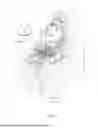
FIGS. 2C and 2B are illustrative views of a crystal structure of the wafer, where FIG. 2B is a partially enlarged view of FIG. 2A. As shown in FIG. 2B, the wafer W is a wafer having an off-cut angle α, and may be, for example, a hexagonal single crystal wafer such as a SiC single crystal wafer or a GaN single crystal wafer. The wafer W is epitaxially grown with the off-cut angle α of approximately from 1 to 4 degrees to reduce crystal defects. The wafer W according to the present embodiment is a SiC single-crystal wafer, and the first major surface W1 of the wafer W is a C-plane, which inclines by the off-cut angle α with respect to the {0001} plane (basal plane).
The wafer W has an off-angle direction D. The "off-cut angle direction D" refers to a direction, as shown in FIG. 2C, from a tip toward a base end of a vector, which is a normal vector P of the {0001} plane of the wafer W projected onto a plane. In this context, an "upstream side of the off-cut angle direction D" refers to a side, toward which the tip of the vector being the normal vector P of the {0001} plane of the wafer W projected onto the plane is pointing. A "downstream side of the off-cut angle direction D" refers to a side opposite to the direction, toward which the tip of vector being the normal vector P of the {0001} plane of the wafer W projected onto the plane is pointing.
FIGS. 3A and 3B each show an exemplary plan view and a front view of a wafer. The wafers W shown in FIGS. 3A and 3B each include a cutout W3, which indicates a crystal orientation, on an outer periphery thereof. The cutout W3 of the wafer W in FIG. 3A is a notch W31, and the cutout W3 of the wafer W in FIG. 3B is an orientation flat W32. The notch W31 is cut out in a recessed shape toward the center of the first major surface W1, and more specifically, is formed in a tapered shape (tapered shape or triangular shape) narrowing toward the center of the first major surface W1. The orientation flat W32 is formed by cutting off a portion linearly in a plan view.
The off-cut angle direction D of the wafer W in FIG. 3A is parallel to a direction orthogonal to a direction that connects the notch W31 and the center of the first major surface W1, and is parallel to a left-right direction in FIG. 3A. The off-cut angle direction D of the wafer W in FIG. 3B is parallel to an extending direction of the orientation flat W32, and is parallel to the left-right direction in FIG. 3B. In both of the wafers W in FIGS. 3A and 3B, the leftward side is the upstream side of the off-cut angle direction D, and the rightward side is the downstream side of the off-cut angle direction D. In the present embodiment, the chuck table 12 holds the wafer W shown in FIG. 3A.
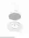
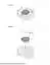
FIG. 4 is a schematic perspective view of the chuck table according to the present embodiment. FIG. 5 is an exploded view of the chuck table shown in FIG. 4. As shown in FIGS. 4 and 5, the chuck table 12 includes, further to the above-described porous member 15, a ring-shaped (annular) frame body 61 disposed so as to surround an outer periphery of the porous member 15, and a disk-shaped base portion 62 disposed below the porous member 15 and the frame body 61. The frame body 61 and the base portion 62 are formed of a dense body.
The porous member 15 is provided in a shape corresponding to the wafer W when viewed along the vertical direction, that is, in a substantially circular shape having a recessed portion 64, which corresponds to the notch W31.
The frame body 61 is formed in an inner peripheral shape having an inner diameter substantially equal to the outer diameter of the porous member 15, and includes a protruding portion 65 having a shape corresponding to the notch W31 of the wafer W and the recessed portion 64 of the porous member 15. Accordingly, the porous member 15 is provided so as to fit inside the frame body 61 from above. With the porous member 15 housed in the frame body 61, an upper surface 66 of the frame body 61 and the holder surface 16, which is the upper surface of the porous member 15, align to form a conical surface.
The base portion 62 is formed to have a diameter larger than the frame body 61 when viewed from above, and has a plurality of holes formed along an outer periphery for inserting fixing screws. The base portion 62 is connected to a lower end of the frame body 61 and forms, together with the frame body 61, a space to accommodate the porous member 15. Accordingly, the porous member 15 is supported from below by an upper surface of the base portion 62 (see FIG. 2A).
On the upper surface of the base portion 62 inside the frame body 61, an annular groove 68 and a passage 69 formed at a bottom of the annular groove 68 (neither is shown in FIG. 4), are formed. The annular groove 68 and the passage 69 communicate with the unshown suction source, and the porous member 15 holds the wafer W by suction against the holder surface 16 under the negative pressure. In a view along the vertical direction, a center position of the base portion 62 coincides with the center CT of the porous member 15, and the base portion 62 is provided concentrically with the porous member 15.
In this arrangement, when viewed along the vertical direction, a center of a circle forming the outer periphery of the frame body 61 is eccentric leftward in FIGS. 4 and 5 with respect to the center CT of the porous member 15. Therefore, when a virtual line extending through the center CT of the porous member 15 and the recessed portion 64 corresponding to the notch W31 is defined as a reference line (hereinafter, "reference line S"), a portion of the upper surface of the frame body 61 on one side (rightward side in FIGS. 4 and 5) of the reference line S in a radial direction and the other portion of the upper surface of the frame body 61 on the other side (leftward side in FIGS. 4 and 5) of the reference line S in the radial direction are in different shapes having different widths in the radial direction. More specifically, the width of the upper surface 66 of the frame body 61 in the radial direction is smallest on the one side and largest on the other side of the reference line S, in an asymmetrical shape between the one portion on the one side and the other portion on the other side of the reference line S in the view along the vertical direction. With the frame body 61 having the upper surface 66 in this shape described above, a path-length varying portion 71, which will be described further below, is formed.
Operations of the components in the grinding apparatus 1 are controlled by a controller 73 (see FIG. 1). The controller 73 includes a processor for executing various processes and a memory for storing, for example, various parameters and programs. The memory stores controlling programs such as, for example, programs for controlling operations of the table moving mechanism 20, the table rotation mechanism 26, the tilt adjustment mechanism 27, the lift/lower unit 30, the grinding unit 40, and the like.
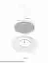
Next, a method for grinding the wafer W using the grinding apparatus 1 configured as described above will be described. The method for grinding the wafer W according to the present embodiment is a method for grinding the wafer W through a holder surface forming step, a holding step, and a grinding step. In the following paragraphs, these steps will be described with reference to FIGS. 6A-6C. FIG. 6A is a plan view to illustrate the holder surface forming step. FIG. 6B is a plan view to illustrate the holding step. FIG. 6C is a plan view to illustrate the grinding step.
In these steps, the rotation axis C1 of the spindle 45 is maintained parallel to the vertical direction, and the rotation axis C2 of the chuck table 12 is inclined relative to the rotation axis C1 of the spindle 45 so that a radial region being a part of the holder surface 16 aligns parallel to the lower surfaces of the grindstones 49.
[Holder Surface Forming Step]
The holder surface forming step is a process called self-grinding, in which the upper surface of the chuck table 12 is ground preparatorily, and the holder surface 16 of the chuck table 12 and the upper surface 66 of the frame body 61 are formed so as to align parallel to the lower end surfaces (grinding surfaces) of the grindstones 49.
In the holder surface forming step, the chuck table 12 is located by driving the table moving mechanism 20 (see FIG. 2A) to a position below the grinding unit 40. At this position, as shown in FIG. 6A, the grindstones 49 are maintained in a state such that a width center of the annularly arrayed grindstones 49 passes straight above the center CT of the porous member 15.
Thereafter, the chuck table 12 is rotated about the rotation axis C2 by the table rotation mechanism 26, and the grindstones 49 are rotated about the rotation axis C1 with the spindle 45 (see FIG. 2A). Therefrom, the grinding unit 40 is lowered by driving the lift/lower unit 30, and the rotating grindstones 49 are moved to contact and pressed against the upper surface of the rotating chuck table 12. Accordingly, both the holder surface 16, which is the upper surface of the porous member 15, and the upper surface 66 of the frame body 61 of the chuck table 12 are ground, and the holder surface 16 and the upper surface 66 form a generally conical surface having the apex at the center CT of the porous member 15.
In the grinding step described later, when the wafer W is being ground with the grindstones 49 while the grindstones 49 and the wafer W are rotated respectively and the grindstones 49 are pressed against the wafer W, the wafer W tends to be thinner on the upstream side compared to the downstream side in the off-cut angle direction D. This is because, as shown in FIGS. 2B and 2C, when grinding from the upstream side toward the downstream side in the off-cut angle direction D, cutting along the off-cut angle direction D is smooth and grinding resistance is relatively small, whereas, when grinding from the downstream side toward the upstream side, the grindstones 49 cutting against the off-cut angle direction D tend to be caught and grinding resistance is relatively large. As a result, there has been a problem that thickness is uneven within the wafer W having been ground.
In order to overcome such a problem, the chuck table 12 of the present embodiment is provided with the path-length varying portion 71 in the frame body 61 so that a path-length difference is created in the grinding paths of the grindstones 49 in the holder surface forming step.
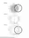
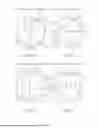
The path-length difference of the grindstones 49 will be described below with reference to FIGS. 7A-7D. FIGS. 7A-7D are illustrative views of the chuck table being ground. FIGS. 7A-7D show states in which the rotation angle of the chuck table 12 are varied. In FIGS. 7A, 7B, 7C, and 7D, the rotation angle is θ degrees, (θ+90) degrees, (θ+180) degrees, and (θ+270) degrees, respectively. In FIGS. 7A-7D, positions of the outer peripheral edge of the annularly arrayed grindstones 49 are indicated in broken lines. In this instance, the grindstones 49 that grind the chuck table 12 contacts the upper surface of the chuck table 12 in an upstream region, with respect to the center CT of the porous member 15, in the rotating direction of the grindstones 49. In this region, an intersection between the outer peripheral edge of the grindstones 49 and the outer peripheral edge of the porous member 15 is referred to as point A, and an intersection between the outer peripheral edge of the grindstones 49 and the outer peripheral edge of the frame body 61 is referred to as point Q.
While the grindstones 49 grind the chuck table 12 in the holder surface forming step, on the chuck table 12 in each rotation angle as shown in FIGS. 7A-7D, a path length of the grindstones 49 that grind the upper surface 66 of the frame body 61 is defined as the length of the outer peripheral edge (arc) of the grindstones 49 extending between the point A and the point Q. When the rotation angle is θ degrees as shown in FIG. 7A and the rotation angle is (θ+90) degrees as shown in FIG. 7B, the path length of the grindstones 49 between point A and point Q is relatively short. On the other hand, when the rotation angle is (θ+180) degrees as shown in FIG. 7C and the rotation angle is (θ+270) degrees as shown in FIG. 7D, the path length of the grindstones 49 between point A and point Q is relatively long. Note that FIGS. 7A-7D show the off-cut angle direction D of the wafer W that is held on the chuck table 12 by an arrow.
The frame body 61 being a dense body has a significantly greater grinding resistance than the porous member 15. Accordingly, in comparing the grinding resistances, the influence of the path length in the porous member 15 is substantially small and negligible. Therefore, the grinding resistance of the grindstones 49 at the rotation angles in FIGS. 7A-7D is generally proportional to the path length of the grindstones 49 for grinding the upper surface 66 of the frame body 61. In this context, on the holder surface 16 of the chuck table 12, with respect to the reference line S as a boundary, which extends through the center CT of the porous member 15, a rightward region in FIG. 5 (a downstream region (one region) in the off-cut angle direction D of the wafer W held on the holder surface 16) is defined as a first region R1, and a leftward region in FIG. 5 (an upstream region (the other region) in the off-cut angle direction D of the wafer W held on the holder surface 16) is defined as a second region R2.
In the states shown in FIGS. 7A and 7B, where the path length of the grindstones 49 between point A and point Q is relatively short, the upper surface 66 of the frame body 61 adjacent to the first region R1 is being ground. In the states shown in FIGS. 7C and 7D, where the path length of the grindstones 49 between point A and point Q is relatively long, the upper surface 66 of the frame body 61 adjacent to the second region R2 is being ground. Therefore, compared to the second region R2, the first region R1 has a shorter path length of the grindstones 49 between point A and point Q, resulting in a smaller grinding resistance and a larger grinding amount on the upper surface of the chuck table 12.
As a result, on the conical holder surface 16 having the apex at the center CT of the porous member 15, a height difference is created across the reference line S between the first region R1 and the second region R2 such that the first region R1 is lower than the second region R2. In other words, in order to create such a height difference, the path-length varying portion 71 forms the shape of the upper surface 66 of the frame body 61 as described above and forms a path-length difference of the grindstones 49 between point A and point Q according to the rotation angle of the chuck table 12. Note that the reference line S being the boundary line between the first region R1 and the second region R2 is the same line as a line serving as a reference for the height difference in the holder surface 16.
[Holding Step]
After the holder surface forming step is performed, as shown in FIG. 6B, the holding step in which the wafer W is held by suction against the holder surface 16 is performed. In the holding step, the wafer W is placed on the holder surface 16 of the chuck table 12 by, for example, an unshown conveyer device. In this instance, the notch W31 of the wafer W is aligned with the recessed portion 64 of the porous member 15, whereby the off-cut angle direction D of the wafer W being held coincides with a direction orthogonal to the reference line S.
After the wafer W is placed on the holder surface 16, the porous member 15 of the chuck table 12 is connected to the unshown suction source. Accordingly, negative pressure is generated in the porous member 15 by suctioning act of the suction source, and the wafer W is held by suction against the holder surface 16 due to the negative pressure. In this instance, the wafer W is deformed into an umbrella shape, where an apex is at the center CT of the porous member 15, along the shape of the holder surface 16 (see FIG. 2A).
[Grinding Step]
After the holding step is performed, the grinding step, in which the wafer W held in the holding step by suction against the holder surface 16 of the chuck table 12 is ground with the grindstones 49, as shown in FIGS. 2A and 6C, is performed.
In the grinding step, while the thickness measuring device 18 measures the thickness of the wafer W, the chuck table 12 is rotated about the rotation axis C2 by the table rotation mechanism 26, and the grindstones 49 are rotated about the rotation axis C1 with the spindle 45. Further, the grinding unit 40 is lowered by driving the lift/lower unit 30, and the rotating grindstones 49 are moved to contact and pressed against the upper surface of first major surface W1 of the rotating wafer W. While the wafer W is being ground, the chuck table 12 is rotated in the same direction as the spindle 45 to rotate the wafer W, and the outer peripheral edge of the grindstones 49 passes over the center of the wafer W. When the thickness of the wafer W being measured by the thickness measuring device 18 reaches a predetermined thickness, the grinding unit 40 is lifted to end the grinding step.
As described above with reference to FIG. 5, when grinding the first major surface W1 (C-plane) of the wafer W having the off-cut angle α, the ground wafer W tends to be thinner on the rightward side than the leftward side (the downstream side than the upstream side in the off-cut angle direction D) with respect to the reference line S2 being the boundary that extends through the center of the cutout W3 of the wafer W and the center of the wafer W . However, in this embodiment, the holder surface 16 is formed to have the height difference such that the first region R1 is lower than the second region R2. Accordingly, the wafer W may be ground to a uniform thickness. That is, the distance between the first region R1 of the holder surface 16 that holds the rightward side of the wafer W with respect to the reference line S2 being the boundary, which tends to be thinner when being ground, and the lower surface of the grindstones 49 is set to be larger than the distance between the second region R2 and the lower surface of the grindstones 49. Therefore, the grinding amount of the portion of the wafer W held on the first region R1 is enabled to be smaller compared to a grinding amount of the wafer W which is ground on a holder surface 16 where no height difference is created between the first region R1 and the second region R2. As a result, in the wafer W having been ground in the grinding step, thickness variations due to the off-cut angle α may be suppressed, and the wafer W may be ground to a uniform thickness.
According to the above embodiment, with the path-length varying portion 71, as shown in FIGS. 7A-7D, the path length in the portion where the grindstones 49 grind the upper surface 66 of the frame body 61 in the holder surface forming step may be varied according to the rotation angle of the chuck table 12. As a result, the height difference is formed across the reference line S between the first region R1 and the second region R2 in the holder surface 16, and the grinding amount within the plane of the wafer W may be varied according to the off-cut angle α of the wafer W. Therefore, when grinding a wafer W having an off-cut angle α, a uniform thickness throughout the wafer W may be achieved.
Moreover, in the above embodiment, the chuck table 12 includes the path-length varying portion 71. Therefore, a configuration, such as that disclosed in Japanese Patent Laid-Open Publication No. 2021-142627, in which the rotation center of the chuck table and the center of the wafer are offset from each other, may be omitted. This may prevent the planar area of the chuck table 12 from increasing and suppress increase of the volume of the chuck table 12 and the overall size of the grinding apparatus 1.
Further, the path-length varying portion 71 is configured by the form of the frame body 61, where the inner periphery and the outer periphery are eccentric. This may prevent the configuration of the chuck table 12 from becoming complicated. Furthermore, the conventional chuck table, in which the inner periphery and the outer periphery of the frame body 61 are concentric, may be easily replaced with the chuck table 12 according to the present embodiment, providing the function and the effects as described.
Note that embodiment of the present disclosure may not necessarily be limited to the configuration described above but may be modified in various ways. In the embodiment described above, sizes or forms of the components illustrated in the accompanying drawings are not limited thereto but may be modified optionally within the scope of the effects of the present disclosure. Moreover, the embodiment may be modified optionally without departing from the scope of the object of the present disclosure.
For example, in the above embodiment, the cutout W3 in the wafer W is provided in the form of the notch W31, but as shown in FIG. 3B, the cutout W3 may be modified into the orientation flat W32. For another example, the planar size of the wafer W may be modified to be substantially smaller than the inner peripheral shape of the frame body 61.
For another example, furthermore, the path-length varying portion 71 may be configured by changing the frame body 61 to another shape, as long as the same functions as those in the above embodiment are achievable. Examples in which at least one of the above-described modified examples is made will be described below as first through third modified examples with reference to FIGS. 8A-8B, 9A-9B, and 10A-10B.
FIG. 8A is a schematic perspective view of a chuck table according of the first modified example. FIG. 8B is an exploded view of the chuck table shown in FIG. 8A. In the first modified example, the cutout W3 in the wafer W in the above embodiment is replaced with an orientation flat W32. Further, the wafer W in the first modified example has a smaller planar size than the wafer W in the above embodiment. The porous member 15 has a planar shape corresponding to the wafer W, and a recessed portion 82 having the same shape as the orientation flat W32 is formed. The chuck table 12 in the first modified example includes a holder wall 81, which is concentric with the inner periphery of the frame body 61, inside the frame body 61. An inner periphery of the holder wall 81 is in a form corresponding to the outer periphery of the porous member 15 having the recessed portion 82. In the first modified example, a passage 83 is formed at a center of the base portion 62 and communicates with the unshown suction source.
In the first modified example, the chuck table 12 is provided with the path-length varying portion 71, which is in the same configuration as that in the above embodiment. Therefore, while a space is formed between the frame body 61 and the porous member 15, through the holder surface forming process, the height difference is created across the reference line S between the first region R1 and the second region R2, in the same manner as that in the embodiment described above.
FIG. 9A is a schematic perspective view of a chuck table according of the second modified example. FIG. 9B is an exploded view of the chuck table shown in FIG. 9A. In the second modified example, the frame body 61 is in a form such that the outer periphery and the inner periphery are concentric, and a path-length varying portion 84 is formed of a shape of the upper surface 66 of the frame body 61. The path-length varying portion 84 in the second modified example is configured such that a plurality of recesses 86 are formed in a portion adjacent to the first region R1. By forming these recesses 86, the grinding path length of the grindstones 49 when grinding the portion where the recesses 86 are formed is shortened, and the path-length varying portion 84 thereby creates a difference in the grinding path length of the grindstones 49 according to the rotation angle of the chuck table 12.
FIG. 10A is a schematic perspective view of a chuck table according of the third modified example. FIG. 10B is an exploded view of the chuck table shown in FIG. 10A. In the third modified example, similarly to the first modified example, the cutout W3 in the wafer W is replaced with the orientation flat W32, and the chuck table 12 includes the holder wall 81, corresponding to the wafer W of the same planar size as the first modified example, inside the frame body 61.
In the third modified example, the frame body 61 includes the path-length varying portion 84 in the same configuration as that in the second modified example. Therefore, while a space is formed between the frame body 61 and the porous member 15, through the holder surface forming process, the height difference is created across the reference line S between the first region R1 and the second region R2.
Optionally, the cutout W3 in the wafer W may be in a form other than the notch W31 or the orientation flat W32. Moreover, the cutout W3 formed in the wafer W is not limited to a single cutout W3, but may include a plurality of cutouts W3. For another example, the wafer W in which no cutout W3 is formed may be used.
The above embodiment explained that the ground wafer W tends to be thinner on the upstream side in the off-cut angle direction D than the downstream side. This thickness difference occurs when grinding a C-plane (first major surface W1) of a wafer W being a SiC wafer; therefore, in a case of grinding a Si-plane of a SiC wafer or a wafer other than SiC wafer, the upstream side in the off-cut angle direction D may be thicker than the downstream side. In such cases, the frame body 61 is formed so that the path lengths of the grindstones 49 on one side and the other side across the reference line S are opposite to those in the above embodiment.
As described above, the present disclosure is effective in that a wafer, such as a SiC wafer having an off-cut angle, may be ground to a uniform thickness, while suppressing an increase in an overall size of a grinding apparatus including a chuck table.
Claims
What is claimed is:1. A chuck table configured to hold a wafer having an off-cut angle by suction for grinding with a grindstone, comprising:
a disk-shaped porous member; and
a path-length varying portion configured to create a path-length difference in paths of the grindstone grinding the porous member such that a holder surface, formed by rotating the porous member about a rotation axis extending through a center of the porous member and grinding an upper surface of the porous member with the grindstone, has a height difference between one side and the other side across a line that extends through the center of the porous member.
2. The chuck table according to claim 1,
wherein the path-length varying portion is a ring-shaped frame body surrounding an outer periphery of the porous member and is configured to create the path-length difference by a shape of an upper surface of the frame body.
3. A method for grinding the wafer having the off-cut angle held on the holder surface of the chuck table according to claim 1 with the grindstone, comprising:
a holder surface forming step including grinding an upper surface of the chuck table that rotates about the rotation axis extending through the center of the porous member into the holder surface in a conical shape having an apex at the center of the porous member and having the height difference across the line that extends through the center of the porous member;
a holding step including causing the holder surface to hold the wafer by suction in an arrangement such that an off-cut angle direction of the wafer coincides with a direction orthogonal to a line serving as a reference for the height difference in the holder surface; and
a grinding step including grinding the wafer rotated by rotation of the chuck table with the grindstone.
4. A method for grinding the wafer having the off-cut angle held on the holder surface of the chuck table according to claim 2 with the grindstone, comprising:
a holder surface forming step including grinding an upper surface of the chuck table that rotates about the rotation axis extending through the center of the porous member into the holder surface in a conical shape having an apex at the center of the porous member and having the height difference across the line that extends through the center of the porous member;
a holding step including causing the holder surface to hold the wafer by suction in an arrangement such that an off-cut angle direction of the wafer coincides with a direction orthogonal to a line serving as a reference for the height difference in the holder surface; and
a grinding step including grinding the wafer rotated by rotation of the chuck table with the grindstone.
Images & Drawings included:


Sources:
- United States Patent and Trademark Office - verify current appl. status at the USPTO↗
Recent applications in this class:
- » 20260048472 2026-02-19
CARRIER HEAD MEMBRANE - » 20260014667 2026-01-15
CARRIER FOR POLISHING WORKPIECES WITH FLATS OR VOIDS - » 20260001191 2026-01-01
ENHANCED SILICON GRIND USING CHEMICAL ADDITIVES IN FLUID DURING GRINDING PROCESS - » 20250381641 2025-12-18
POLISHING APPARATUS AND SUBSTRATE POLISHING METHOD - » 20250235980 2025-07-24
SUBSTRATE LAPPING APPARATUS AND SUBSTRATE LAPPING METHOD USING THE SAME - » 20250229378 2025-07-17
SUBSTRATE PROCESSING APPARATUS - » 20250205848 2025-06-26
POLISHING HEAD FOR SUBSTRATE POLISHING - » 20250196287 2025-06-19
POLISHING SYSTEMS AND METHODS - » 20250114903 2025-04-10
RETAINING-RING-LESS CMP PROCESS - » 20250114902 2025-04-10
HORIZONTAL PRE-CLEAN 2-STAGE DOWNFORCE MECHANISM WITH FLEXURE