EJECTOR-TYPE VACUUM PUMP ASSEMBLY HAVING STABILISED MEMBRANE FLOW VALVE, AND A FLOW CONTROL UNIT HAVING STABILISED MEMBRANE FLOW VALVE FOR USE WITH AN EJECTOR-TYPE VACUUM PUMP OF SUCH ASSEMBLY, AND A METHOD OF CON-TROLLING A VACUUM LEVEL IN A VACUUM CHAMBER OF AN EJECTOR-TYPE VACUUM PUMP OF THE ASSEMBLY
US20260098529A1
2026-04-09
19/351,797
2025-10-07
Smart Summary: An ejector-type vacuum pump assembly uses a special valve to control how air flows through it. A small amount of pressurized air, called pilot flow, helps manage a larger flow of air that powers the pump. This setup is mainly designed for machines that need to grip objects using suction. There is also a unit that helps control the air flow to the pump more precisely. Additionally, a method is provided to adjust the vacuum level inside the pump's chamber. 🚀 TL;DR
Abstract:
An ejector-type vacuum pump assembly containing a stabilizing membrane flow valve, wherein a pilot flow of pressurized air is used to regulate a main flow of pressurized air for driving an ejector-type vacuum pump is disclosed. The pilot flow is led to a downstream side of the membrane flow valve and is fed to the ejector of the ejector-type vacuum pump along with the main flow of pressurised air. The ejector-type vacuum pump assembly is primarily intended for automated gripping operations using a suction gripper. Also disclosed is a flow control unit for controllably exiting a flow of pressurized air to be fed to an ejector-type vacuum pump in the ejector-type vacuum pump assembly, and a method of controlling a vacuum level in a vacuum chamber of an ejector-type vacuum pump in an ejector-type vacuum pump assembly as described herein.
Applicant:
Interested in similar patents?
Get notified when new applications in this technology area are published.
Classification:
F04B45/06 » CPC main
Pumps or pumping installations having flexible working members and specially adapted for elastic fluids having tubular flexible members
F04B49/22 » CPC further
Control, e.g. of pump delivery, or pump pressure of, or safety measures for, machines, pumps, or pumping installations, not otherwise provided for, or of interest apart from, groups - by means of valves
F04B51/00 » CPC further
Testing machines, pumps, or pumping installations
Description
CROSS REFERENCE TO RELATED APPLICATIONS
The present application claims priority to European Patent Application No. 24205248.8, filed October 8, 2024, the entire contents of which is incorporated herein for all purposes by this reference.
FIELD OF THE INVENTION
The present invention relates to an ejector-type vacuum pump assembly comprising a stabilizing membrane flow valve, wherein a pilot flow of pressurized air is used to regulate a main flow of pressurized air for driving an ejector-type vacuum pump. The pilot flow is led to a downstream side of the membrane flow valve and is fed to the ejector of the ejector-type vacuum pump along with the main flow of pressurised air. The ejector-type vacuum pump assembly is primarily intended for automated gripping operations using a suction gripper fluidly connected to a suction opening of the ejector-type vacuum pump. The present disclosure also relates to a flow control unit for controllably exiting a flow of pressurized air to be fed to an ejector-type vacuum pump in the inventive ejector-type vacuum pump assembly. The present disclosure further relates to a method of controlling a vacuum level in a vacuum chamber of an ejector-type vacuum pump in an ejector-type vacuum pump assembly as disclosed herein.
BACKGROUND ART
In automated gripping operations using a suction gripper, an ejector-type vacuum pump is often used to generate the required suction power. Generation of pressurized air is however energy demanding and reduction of energy consumption is desirable. In instances when there is essentially no, or only a negligible leakage between a suction gripper and a surface of an object being gripped by the gripper, in order to reduce energy consumption, the flow of pressurized air can be stopped when a vacuum level in the gripper is at a sufficiently high level, and then started again, when the vacuum level has reached a given lower limit.
However, about 90 % of all gripping operations involves leaking surfaces and/or leaking materials. Cardboard is a material that will in most, if not all, instances produce a leakage when placed against a suction gripper. The degree of leakage can differ from one type of cardboard to another, and even between different batches of one and the same type of cardboard, making it more difficult to identify and adapt a sufficient flow of pressurized air to the injector of the vacuum pump for objects to be handled by the gripper. If the flow of pressurized air is turned off, the gripped object may fall off from the gripper. Accordingly, for gripping operations involving gripping cardboard surfaces, such as cardboard boxes, to minimize the risk of an object being dropped from the gripper, the flow of pressurized air is typically regulated to maximum flow. Moreover, a gripper system should be dimensioned for the highest possible leakage and the most inaccurate, yet acceptable within certain limits, positioning of the gripper against the surface of an object.
Accordingly, it would be desirable to be able to reduce the overall energy consumption in gripping operations involving leaking surfaces and/or leaking materials.
It is therefore an object of the present disclosure to provide an ejector-type vacuum pump assembly enabling reducing the overall energy consumption in gripping operations involving leaking surfaces and/or leaking materials.
In gripping operations involving gripping of plastic bags, suction cups having a lip as pliant and flexible as the plastic bags themselves to be handled are typically used. If the vacuum level is too high, the grip may be inferior due to collapsing of the lip of the suction cup, and the plastic bag might be dropped from the suction cup. Also, higher vacuum levels will incur more wear on the vacuum cups, and will often produce marks on the plastic bags, and sometimes even holes in the plastic bags.
It is challenging to create a fully balanced valve-system capable of regulating flow (and thereby pressure) to a compressed air consumer, such as an ejector-type vacuum pump. Such a system typically requires high tolerance machined parts with sliding seals in order to maintain balance and minimize “slip-stick” causing irregularities in the adjustment of the valve-system.
Accordingly, it would be desirable to be able to control the vacuum level in the suction cup to a given lower desired level, preferably while minimizing any “slip-stick” behaviour.
It is therefore a further object of the present disclosure to provide an ejector-type vacuum pump assembly enabling controlling the vacuum level in the suction cup to a given lower desired level.
SUMMARY
The above two objects have been accomplished by means of the ejector-type vacuum pump assembly disclosed herein.
The present disclosure is based on, utilizing pneumatic forces, regulating a flow valve for pressurized air using another smaller valve.
Accordingly, it has been found that a certain membrane valve could be used for stabilizing a desired vacuum level in an ejector-type vacuum pump assembly, wherein a small control valve regulates the flow of pressurized air to the ejector so as to correspond to a desired vacuum level in a vacuum chamber of the injector.
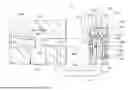
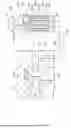
Accordingly, in one aspect the disclosure relates to an ejector-type vacuum pump assembly 15 comprising an ejector-type vacuum pump 410 fluidly connected to a flow control unit 400, wherein the ejector-type vacuum pump 410 comprises: a pressure chamber 110, an ejector nozzle 120, a vacuum chamber 130, a suction opening 105, and an exhaust 140, the ejector nozzle 120 fluidly connecting the vacuum chamber 130 with the pressure chamber 110; and wherein the flow control unit 400 comprises: an inlet 20 for pressurized air; a first flow-control valve 200 comprising: a valve chamber 210, the first flow-control valve 200 being configured to control a flow of pressurized air exiting the valve chamber 210 to be fed to the ejector-type vacuum pump 410, the valve chamber 210 being fluidly connected to the inlet 20 for pressurized air; wherein the valve chamber 210 comprises: a bottom 215 having an opening 217, a wall 225 having an orifice 230 configured to exiting the flow of pressurized air from the valve chamber 210; wherein, in the valve chamber 210 of the first flow-control valve 200, a collapsible, flexible, cylindrical membrane 220 is housed, the collapsible, flexible, cylindrical membrane 220 being configured to seal against the bottom 215 and/or to the wall 225, and, in a relaxed, un-collapsed state of the outer collapsible, flexible cylindrical membrane 220, to seal the orifice 230, the first flow-control valve 200 further comprising an inner rigid flow chamber 240 comprising, in an upstream end 250 thereof, a flow restriction 260 fluidly connecting the valve chamber 210 with the rigid inner flow chamber 240, and, in a downstream end 255 thereof, an opening 257 fluidly connected to the opening 217, the rigid inner flow chamber 240 having in a side wall 245 an orifice 270 fluidly connecting the inner flow chamber 240 with an inner volume 280 of the first flow-control valve 200, said inner volume 280 enveloped by the collapsible, cylindrical, flexible membrane 220 and the bottom 215; the upstream end 250 of the rigid flow chamber 240 being sealingly connected to an opening 227 in an upstream end 222 of the collapsible, cylindrical, flexible membrane 220; and wherein the flow control unit 400 additionally comprises a second flow-control valve 300 configured to regulate a pilot flow of pressurized air exiting the inner flow chamber 240 to be fed to the ejector-type vacuum pump 410.
The present disclosure does not include a sliding member, and therefore avoids any slip-stick behaviour or other irregular motions typically encountered due to friction when a sliding motion of one part in relation to another part is involved, or even is being relied upon.
Preferably, the ejector-type vacuum pump assembly 15 additionally comprises a pressure sensor 150 configured to sense a pressure P in the vacuum chamber 130, which pressure sensor is located in the vacuum chamber 130.
While control of the vacuum level in vacuum chamber 130 could be carried out manually by manually regulating flow-control valve 300, the vacuum level in vacuum chamber 130 of the ejector-type vacuum pump assembly 15 can be controlled by a control unit CU, also referred to as a controller.
Accordingly in an embodiment of the ejector-type vacuum pump assembly 15, the pressure sensor 150 is additionally configured to send a pressure control signal S1 proportional to the pressure P sensed; and the ejector-type vacuum pump assembly 15 additionally comprises: a controller CU configured to receive a pressure control signal S1 from the pressure sensor 150, to compare the pressure control signal S1 received with a desired target pressure P TARGET, to establish any existence of a pressure difference ΔP between the pressure sensed P and a desired target pressure P TARGET, and, in the case of an established existence of a pressure difference ΔP between the pressure sensed P and the desired target pressure P TARGET, to send a flow control actuation signal S2 to the second flow-control valve 300 corresponding to the sign (i.e. “+” or “-“) of the pressure difference ΔP established between the pressure sensed P and the desired target pressure P TARGET.
A vacuum level in the vacuum chamber 130 is measured, and the measured value is used to control the opening state of a flow-control valve 300, which flow-control valve in turn regulates the feed pressure in the ejector pressure chamber 110, and thereby indirectly regulates the vacuum level in the vacuum chamber 130 (i.e. utilizing a regular PID-control algorithm well balanced to the control system fluid dynamics).
Accordingly, in another aspect, disclosed is a method of controlling a vacuum level in a vacuum chamber of an ejector-type vacuum pump in an ejector-type vacuum pump assembly, comprising the following steps: A supplying pressurized air to an ejector-type vacuum pump assembly 15; B monitoring a pressure P in a vacuum chamber 130 of an ejector-type vacuum pump 410 of the ejector-type vacuum pump assembly 15; and, C controlling a flow-control valve 300 based on the pressure P monitored, thereby regulating a pilot flow of pressurized air through the flow-control valve 300; wherein a pressure differential between a reduced pressure produced by the pilot flow of pressurized air, and the pressure of the pressurized air being supplied to the ejector-type vacuum pump assembly 15 in step A, regulates a flow of pressurized air driving the ejector-type vacuum pump 410.
The disclosed method enables setting a desired vacuum level to be maintained in the vacuum chamber of the ejector, and keeping this level, using a pressure sensor in the ejector vacuum chamber, a flow control valve, and a control unit.
Accordingly, in an embodiment of the method, a control unit CU is used to maintain a desired target pressure in vacuum chamber 130, wherein step B includes sensing a pressure P in the vacuum chamber 130 and sending a pressure control signal S1 to the control unit CU proportional to the pressure P sensed in the in vacuum chamber 130, and wherein step C includes comparing the pressure control signal S1 received with a desired target pressure P TARGET, establishing any potential existence of a pressure difference Δ P between the pressure sensed P and the desired target pressure P TARGET, and, in the case of an established existence of a pressure difference Δ P between the pressure sensed P and the desired target pressure P TARGET, sending to the flow-control valve 300 a flow control actuation signal S2 corresponding to the sign (+/-) of the pressure difference Δ P established between the pressure sensed P and the desired target pressure P TARGET.
The assembly can rapidly compensate for a difference in the vacuum level in the vacuum chamber as compared to a desired target pressure, and, at the same time, safeguard that only a feed flow of pressurized air necessary for obtaining and maintaining the target vacuum level is being used by the assembly.
The assembly allows for maintaining a high precision control of a desired vacuum pressure, without any undesired fluctuations in the resulting pressure caused by friction of sliding parts, such as slip-stick behaviour.
The system offers inexpensive means of reducing energy consumption of an ejector-type vacuum pump assembly.
Actuation of the main flow valve will incur minimum wear on the main valve.
Also, the system will produce a minimum of heat as a result of the forces applied to the main valve being sourced from the compressed air pressure rather from electrical actuations.
The assembly can be made very compact, and even a relatively small assembly can allow for a large flow of pressurized air, and the assembly can accordingly be made very size-efficient.
In the assembly 15, the flow control unit 400 including the first flow control valve 200 and second flow-control valve 300, is connected to an ejector-type vacuum pump 410 via conduits 403 and 405, such as e.g. tubings or hoses.
Accordingly, in yet another aspect, the disclosure relates to a flow control unit 400 for controllably exiting a flow of pressurized air to be fed to an ejector-type vacuum pump 410, said unit comprising: an inlet 20 for pressurized air; a first flow-control valve 200 comprising: a valve chamber 210, the first flow-control valve 200 being configured to control a flow of pressurized air exiting the valve chamber 210 to be fed to the ejector-type vacuum pump 410, the valve chamber 210 being fluidly connected to the inlet 20 for pressurized air; the valve chamber 210 comprising: a bottom 215 having an opening 217, a wall 225 having an orifice 230 configured to exiting the flow of pressurized air from the valve chamber 210; wherein, in the valve chamber 210 of the first flow-control valve 200, a flexible, collapsible, cylindrical membrane 220 is housed, the flexible, collapsible, cylindrical membrane 220 being configured to seal against the bottom 215 and/or to the wall 225, and, in a relaxed, un-collapsed state of the collapsible, flexible cylindrical membrane 220, to seal the orifice 230, the first flow-control valve 200 further comprising an inner rigid flow chamber 240 comprising, in an upstream end 250 thereof, a flow restriction 260 fluidly connecting the valve chamber 210 with the rigid inner flow chamber 240, and, in a downstream end 255 thereof, an outlet 257 fluidly connected to the opening 217, the rigid inner flow chamber 240 having in a side wall 245 an orifice 270 fluidly connecting the inner flow chamber 240 with an inner volume 280 enveloped by the collapsible, cylindrical, flexible membrane 220 and the bottom 215, the upstream end 250 of the rigid flow chamber 240 being sealingly connected to an opening 227 in an upstream end 222 of the collapsible, cylindrical, flexible membrane 220, the flow control unit 400 additionally comprising: a second flow-control valve 300 configured to regulate a pilot flow of pressurized air exiting the inner flow chamber 240 to be fed to the ejector-type vacuum pump 410.
Accordingly, the flow control unit 400 can be used in the assembly 15.
While control of the vacuum level in vacuum chamber 130 could be carried out manually by manually regulating flow-control valve 300, the vacuum level in vacuum chamber 130 of the ejector-type vacuum pump assembly 15 can be controlled by a control unit CU, also referred to as a controller.
Accordingly in an embodiment of the disclosed ejector-type vacuum pump assembly 15, the pressure sensor 150 is additionally configured to send a pressure control signal S1 proportional to the pressure P sensed; and the ejector-type vacuum pump assembly 15 additionally comprises: a controller CU configured to receive a pressure control signal S1from the pressure sensor 150, to compare the pressure control signal S1 received with a desired target pressure P TARGET, to establish any existence of a pressure difference ΔP between the pressure sensed P and a desired target pressure P TARGET, and, in the case of an established existence of a pressure difference ΔP between the pressure sensed P and the desired target pressure P TARGET, to send a flow control actuation signal S2 to the second flow-control valve 300 corresponding to the sign (i.e. “+” or “-“) of the pressure difference ΔP established between the pressure sensed P and the desired target pressure P TARGET.
Further embodiments and advantages of the disclosure will be apparent from the following detailed description and appended claims.
BRIEF DESCRIPTION OF THE ATTACHED DRAWING
The Figure shows a cross-sectional view of an embodiment of an ejector-type vacuum pump assembly 15 as described herein, wherein a flow-control unit 400 including the first flow-control valve 200 is fluidly connected to an ejector-type vacuum pump 410 via tubings 403 and 405.
DETAILED DESCRIPTION
The present disclosure uses a cylindrical servo-valve 200 capable of regulating a feed pressure to an ejector-type vacuum pump 410 via a re-useable bypass flow.
Accordingly, the valve with has a flow-capacity that can be controlled via a pilot airflow in order to supply an ejector-type vacuum pump 410 with a controlled feed pressure so as to be able to control the vacuum-level, i.e. the pressure, P in the ejector.
The side wall 245 of the inner rigid flow chamber 240 is rigid so as to maintain geometrical integrity of flow chamber 240, also at instances when a pressure differential over the wall is present. The flow chamber 240 is surrounded by the collapsible, cylindrical, flexible membrane 220. The flow chamber 240 is preferably tubular, and is preferably essentially concentric with the collapsible, cylindrical, flexible membrane 220.
When flow-control valve 300 is in a closed state and pressurized air is supplied to inlet 20, inner, rigid flow chamber 240 and valve chamber 210, the inner volume 280 of the collapsible, cylindrical, flexible membrane 220, being connected with inner, rigid flow chamber 240 via orifice 270 in the wall 245 of the inner rigid flow chamber 240, will be pressurized by the internal pressure building up in the inner rigid flow chamber 240. When the internal pressure in the inner rigid flow chamber 240 is equal to the feed pressure of the pressurized air entering inlet 20, opening 230 will be sealed off by the collapsible, cylindrical, flexible membrane 220, which is in its relaxed state, and therefore in contact with the wall 225 of the valve chamber 210. At this pressurized state, the pressures in the valve chamber 210, in the flow chamber 240, and in the inner volume 280 of the collapsible, cylindrical, flexible membrane 220, respectively, will be equal, and also equal to the pressure of the pressurized air being supplied to inlet 20.
Now, upon opening of flow-control valve 300 from the above closed state while pressurized air is supplied to inlet 20, a flow of air from the opening 257 in the downstream end of inner rigid flow chamber 240 will be established, and thereby, a pressure-drop over the restriction 260 will be created, causing the pressure in the flow chamber 240 to become smaller than the inlet pressure of the pressurized air being supplied to inlet 20.
The collapsible, cylindrical, flexible membrane 220 will collapse gradually due to the pressure-gradient between the inner volume 280 of the collapsible, cylindrical, flexible membrane 220 and the flow chamber 240, and thereby an airflow is created through orifice 230 from valve chamber 210 to the pressure chamber 110. The airflow from orifice 230 through conduit 403 builds pressure in pressure chamber 110, which pressure in turn will limit the airflow through flow-control valve 300, and balance the collapsible, cylindrical, flexible membrane 220 and limit the airflow through orifice 230 through which pressurized air will be supplied to the pressure chamber 110 from the valve chamber 210.
The combined airflows from orifice 230, via conduit 403, and from flow-control valve 300, via conduit 405, are then expanded through the ejector-type vacuum pump 410 creating a reduced pressure in vacuum chamber 130.
By controlling the by-pass flow via the flow-control valve 300 the pressure in the pressure chamber 110 can then be controlled in a balanced manner due to the pressure-feedback provided via the by-pass connection from flow-control valve 300 to the pressure chamber 110. Increasing the flow exiting the flow chamber 240 by opening the flow-control valve 300 creates a larger pressure-drop between the pressure in the flow chamber 240 and the inlet pressure of the pressurized air being supplied to inlet 20, thereby allowing for the collapsible, cylindrical, flexible membrane 220 to collapse further, thereby opening a larger section of the orifice 230 through which pressurized air will be supplied to the pressure chamber 110 from the valve chamber 210 via conduit 403.
The purpose of the disclosure is to measure and feedback the vacuum-level created in vacuum chamber 130, and to control the vacuum level therein.
A multitude of orifices 230 can be included in the flow control unit 400, which orifices are preferably distributed along the periphery of the wall 225 of the valve chamber 210. In an ejector-type vacuum pump assembly 15, all orifices 230 should be fluidly connected to the pressure chamber 110 of the injector-type vacuum pump 400. The orifices 230 are preferably located at a height of the wall 225 corresponding to a height of the collapsible, cylindrical, flexible membrane 220 just below a height where the upstream end 222 of the collapsible, cylindrical, flexible membrane 220 when in its relaxed state reaches and contacts the wall 225. The upstream end 222 is preferably rounded such as essentially hemispherical. It is believed that a relatively high positioning of the orifices 230 will serve to reduce the extent of flexing of the membrane along its height, and the degree of collapsing of the membrane required for opening the orifices, which in turn is believed to further enhance the stability of the inventive flow control.
The ejector-type vacuum pump assembly 15 can be used with one or more suction grippers, e.g. suction cups or suction pads, fluidly connected to suction opening 105.
The flow-control valve 300 can for example be a manually operated needle valve, a stepper-motor controlled needle valve, a solenoid proportional valve, a linear directly operated solenoid valve, or a linear micro flow piezo-valve. For a close and simplified regulation of flow control valve 130, said valve is preferably a linear valve.
As will be understood from the present disclosure, the flow valve, pressure and flow control can be realized without any sliding elements, thereby avoiding all issues that potentially arise with friction and initial slip-stick. This creates the possibility to have a smooth regulation, without undesired step-changes due to friction. Moreover, the realization of the flow valve, pressure and flow control can be accomplished without strict requirements on tolerances.
In an embodiment, a controller is used to control the control flow-valve 300. The controller CU is preferably a PID controller. A regular PID control with vacuum-level in chamber 130 used as feedback and setpoint signal will require some initial tuning for stability and speed.
The CU, having received a pressure control signal S1 from the pressure sensor 150, compares said pressure control signal S1 received with a desired target pressure P TARGET, to establish a potential existence of a pressure difference ΔP between the pressure sensed P and a desired target pressure P TARGET.
The pressure difference ΔP can be established by subtraction of P TARGET from the pressure sensed P. In such case, an established positive pressure difference ΔP represents a too high pressure in the vacuum chamber (i.e. a too low vacuum level), in which case the flow control actuation signal S2 from the CU will be to open the second flow-control valve 300. Conversely, an established negative pressure difference ΔP represents a too low pressure in the vacuum chamber (i.e. a too high vacuum level), in which case the flow control actuation signal S2 from the CU will be to close the second flow-control valve 300.
Obviously, the pressure difference ΔP could alternatively be established by subtraction of the pressure sensed P from the target pressure P TARGET.
The flow control actuation signal S2 is accordingly intended to reduce any pressure difference ΔP established between P TARGET and the pressure sensed P by corresponding adaptation of the opening state of the second flow-control valve 300. The flow control actuation signal S2 could e.g. correspond to a pre-determined discrete step-wise alteration of the opening state of the valve, or could be proportional to the pressure difference ΔP established between P TARGET and the pressure sensed P.
A user of the system can readily control the vacuum-level in vacuum chamber 130 of a process or handling application with high precision. This enables a significant potential for saving energy as compared to operating at full air-pressure, as well as for improving productivity by increasing the precision and limiting the variation in vacuum-level in a process. The present invention offers a huge potential in energy saving and cost for compressed air.
For example, in a handling application handling cardboard boxes, the cardboard quality will typically vary between suppliers and batches and even with environmental parameters such as humidity. This will require the handling application to be tuned to handle the worst cardboard on the worst day in order to maintain desired process stability. With the present system, the system can be sized for the worst cardboard on the worst day, but tuned automatically for every handled box to only use as much compressed air as needed to create the vacuum-level required.
LIST OF REFERENCE NUMERALS USED
15 ejector-type vacuum pump assembly
20 inlet for pressurized air
105 suction opening
110 pressure chamber
120 ejector nozzle
130 vacuum chamber
140 exhaust
150 pressure sensor
200 first flow-control valve
210 valve chamber
215 bottom of valve chamber
217 opening in bottom of valve chamber
220 collapsible, cylindrical, flexible membrane
222 upstream end of collapsible, cylindrical, flexible membrane
225 wall of valve chamber
227 opening in upstream end of collapsible, cylindrical, flexible membrane
230 orifice in wall of valve chamber
240 inner rigid flow chamber
245 side wall of inner rigid flow chamber
250 upstream end of inner rigid flow chamber
255 downstream end of inner rigid flow chamber
257 opening in downstream end of inner rigid flow chamber
260 flow restriction
270 orifice in wall of inner rigid flow chamber
280 inner volume of first flow-control valve
300 second flow-control valve
400 flow control unit
403 conduit fluidly connecting pressure chamber 110 with orifice 230
405 conduit fluidly connecting inner rigid flow chamber 240 with pressure chamber 110
410 ejector-type vacuum pump
P pressure in vacuum chamber 130
S1 pressure control signal proportional to pressure P
S2 flow control actuation signal
CU controller
PTARGET desired target pressure in vacuum chamber 130
ΔP difference between the pressure P sensed and desired target pressure PTARGET
Claims
1. An ejector-type vacuum pump assembly, said ejector-type vacuum pump assembly comprising:
an ejector-type vacuum pump comprising:
a pressure chamber;
an ejector nozzle;
a vacuum chamber;
a suction opening; and
an exhaust, the ejector nozzle fluidly connecting the vacuum chamber with the pressure chamber; and,
a flow control unit for controllably exiting a flow of pressurized air to be fed to an ejector-type vacuum pump, said unit comprising:
an inlet for pressurized air;
first flow-control valve comprising:
a valve chamber, the first flow-control valve being configured to control a flow of pressurized air exiting the valve chamber to be fed to the ejector-type vacuum pump, the valve chamber being fluidly connected to the inlet for pressurized air;
the valve chamber comprising:
a bottom having an opening, a wall having an orifice configured to exit the flow of pressurized air from the valve chamber;
wherein, in the valve chamber of the first flow-control valve, a flexible, collapsible, cylindrical membrane is housed, the flexible, collapsible, cylindrical membrane being configured to seal against the bottom and/or to the wall, and, in a relaxed, un-collapsed state of the collapsible, flexible cylindrical membrane, to seal the orifice, the first flow-control valve further comprising an inner rigid flow chamber comprising, in an upstream end thereof, a flow restriction fluidly connecting the valve chamber with the rigid inner flow chamber, and, in a downstream end thereof, an outlet fluidly connected to the opening, the rigid inner flow chamber having in a side wall an orifice fluidly connecting the inner flow chamber with an inner volume enveloped by the collapsible, cylindrical, flexible membrane and the bottom, the upstream end of the rigid flow chamber being sealingly connected to an opening in an upstream end of the collapsible, cylindrical, flexible membrane, the flow control unit additionally comprising:
a second flow-control valve configured to regulate a pilot flow of pressurized air exiting the inner flow chamber to be fed to the ejector-type vacuum pump.
wherein the pressure chamber of the ejector-type vacuum pump is fluidly connected to the orifice and to a downstream side of the second flow-control valve.
2. The ejector-type vacuum pump assembly of claim 1, additionally comprising a pressure sensor configured to sense a pressure (P) in the vacuum chamber.
3. The ejector-type vacuum pump assembly of claim 2, wherein the pressure sensor is additionally configured to send a pressure control signal (S1) proportional to the pressure (P) sensed; and wherein the ejector-type vacuum pump assembly additionally comprises:
a controller (CU) configured to receive a pressure control signal (S1) from the pressure sensor, to compare the pressure control signal (S1) received with a desired target pressure (PTARGET), to establish any existence of a pressure difference (ΔP) between the pressure sensed (P) and a desired target pressure (PTARGET), and, in the case of an established existence of a pressure difference (ΔP) between the pressure sensed (P) and the desired target pressure (PTARGET), to send a flow control actuation signal (S2) to the second flow-control valve corresponding to the sign (+/-) of the pressure difference (ΔP) established between the pressure sensed (P) and the desired target pressure (PTARGET).
4. A method of controlling a vacuum level in a vacuum chamber of an ejector-type vacuum pump in an ejector-type vacuum pump assembly of claim 1, comprising the following steps:
A supplying pressurized air to an ejector-type vacuum pump assembly;
B monitoring a pressure (P) in a vacuum chamber of an ejector-type vacuum pump of the ejector-type vacuum pump assembly; and,
C controlling a flow-control valve based on the pressure (P) monitored, thereby regulating a pilot flow of pressurized air through the flow-control valve;
wherein a pressure differential between a reduced pressure produced by the pilot flow of pressurized air, and the pressure of the pressurized air being supplied to the ejector-type vacuum pump assembly in step A, regulates a flow of pressurized air driving the ejector-type vacuum pump.
5. The method of controlling a vacuum level in a vacuum chamber of an ejector-type vacuum pump in an ejector-type vacuum pump assembly of claim 4, wherein a control unit (CU) is used to maintain a desired target pressure in vacuum chamber, wherein step B includes sensing a pressure (P) in the vacuum chamber and sending a pressure control signal (S1) to the control unit (CU) proportional to the pressure (P) sensed in the in vacuum chamber, and wherein step C includes comparing the pressure control signal (S1) received with a desired target pressure (PTARGET), establishing any possible existence of a pressure difference (ΔP) between the pressure sensed (P) and the desired target pressure (PTARGET), and, in the case of an established existence of a pressure difference (ΔP) between the pressure sensed (P) and the desired target pressure (PTARGET), sending to the flow-control valve a flow control actuation signal (S2) corresponding to the sign (+/-) of the pressure difference (ΔP) established between the pressure sensed (P) and the desired target pressure (PTARGET).
6. A flow control unit for controllably exiting a flow of pressurized air to be fed to an ejector-type vacuum pump, for use in the assembly of claim 1, said unit comprising:
an inlet for pressurized air;
a first flow-control valve comprising:
a valve chamber, the first flow-control valve being configured to control a flow of pressurized air exiting the valve chamber to be fed to the ejector-type vacuum pump, the valve chamber being fluidly connected to the inlet for pressurized air;
the valve chamber comprising:
a bottom having an opening, a wall having an orifice configured to exiting the flow of pressurized air from the valve chamber;
wherein, in the valve chamber of the first flow-control valve, a flexible, collapsible, cylindrical membrane is housed, the flexible, collapsible, cylindrical membrane being configured to seal against the bottom and/or to the wall, and, in a relaxed, un-collapsed state of the collapsible, flexible cylindrical membrane, to seal the orifice, the first flow-control valve further comprising an inner rigid flow chamber comprising, in an upstream end thereof, a flow restriction fluidly connecting the valve chamber with the rigid inner flow chamber, and, in a downstream end thereof, an outlet fluidly connected to the opening, the rigid inner flow chamber having in a side wall an orifice fluidly connecting the inner flow chamber with an inner volume enveloped by the collapsible, cylindrical, flexible membrane and the bottom, the upstream end of the rigid flow chamber being sealingly connected to an opening in an upstream end of the collapsible, cylindrical, flexible membrane, the flow control unit additionally comprising:
a second flow-control valve configured to regulate a pilot flow of pressurized air exiting the inner flow chamber to be fed to the ejector-type vacuum pump.
Images & Drawings included:
Sources:
- United States Patent and Trademark Office - verify current appl. status at the USPTO↗
Recent applications in this class:
- » 20250092869 2025-03-20
PUMP FOR ARTICLE OF FOOTWEAR OR APPAREL - » 20240167467 2024-05-23
LONGITUDINAL IMPEDANCE PUMP - » 20230072779 2023-03-09
PUMP, CHEMICAL LIQUID SUPPLYING UNIT, AND SUBSTRATE TREATING APPARATUS - » 20230033238 2023-02-02
Pump for article of footwear or apparel - » 20210017977 2021-01-21
AIR BLOWING DEVICE - » 20200362847 2020-11-19
Pump Body Assembly, Pump, Sprinkler System, and Unmanned Aerial Vehicle - » 20170356435 2017-12-14
SYSTEM, METHOD, AND APPARATUS FOR UTILIZING A PUMPING CASSETTE - » 20140286794 2014-09-25
System, method, and apparatus for utilizing a pumping cassette