CENTRIFUGAL PUMP IMPELLER WITH INVERTED EXPULSION CHAMBERS
US20260098543A1
2026-04-09
19/325,285
2025-09-10
Smart Summary: A new type of impeller is designed for centrifugal pumps. It has a flat circular part called a shroud with a central hub that connects to a rotating shaft. This impeller features special channels, known as inverted expulsion chambers, that extend outward from the center to the edge of the shroud. These chambers help improve the efficiency of the pump by directing the flow of liquid more effectively. Overall, the design aims to enhance how the pump moves fluids. 🚀 TL;DR
Abstract:
An impeller for a centrifugal pump includes a shroud, wherein the shroud is a substantially planar circular section of material. The impeller includes a hub portion disposed in the center of the shroud; the hub configured to connect the impeller to a driveshaft for rotation in a preferred direction. The impeller also includes a plurality of inverted expulsion chambers, wherein each inverted expulsion chamber comprises a channel-shaped relief in the shroud extending radially towards an outer perimeter of the shroud.
Applicant:
Interested in similar patents?
Get notified when new applications in this technology area are published.
Classification:
F04D29/2272 » CPC main
Details, component parts, or accessories; Rotors specially for centrifugal pumps with special measures for influencing flow or boundary layer
F04D1/00 » CPC further
Radial-flow pumps, e.g. centrifugal pumps; Helico-centrifugal pumps
F04D1/00 » CPC further
Pumping liquids, or liquids and elastic fluids, by rotary pumps
F04D29/22 IPC
Details, component parts, or accessories; Rotors specially for centrifugal pumps
Description
CROSS REFERENCE TO RELATED APPLICATIONS
This application claims benefit of U.S. Provisional Application No. 63/703,852, filed October 4, 2024, entitled CENTRIFUGAL PUMP IMPELLER WITH INVERTED EXPULSION CHAMBERS (Atty. Dkt. No. CPMP01-00007), the specifications of which are incorporated by reference herein in their entirety.
TECHNICAL FIELD
The present disclosure relates to pump design, in particular pumps suitable for use with heterogeneous media comprising solids and liquids, including, without limitation, sewage. More specifically, the present disclosure relates to centrifugal pump impellers with inverted expulsion chambers and/or standard impellers with extended expulsion vanes.
BACKGROUND
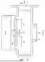
Heterogenous media, such as sewage, in which solids, in particular, stringy solids are mixed in with liquids present unique challenges in the field of pump design. While centrifugal pumps (see, e.g., FIGS. 3 and 3A or FIG. 4) comprising a rotating impeller 300, 400 and raised impeller vanes 301, 401 can pump sewage and other media containing stringy solids, such designs force users to choose between one or more undesirable design tradeoffs. This is due, in part, to the fact that such impeller vanes 301, 401 protrude into a clear space between the impeller shroud and the casing 302, 402, creating catch points between upper portions of protruding vanes and the casing 302, 402, in which solids can become wedged between vanes and pump casings. While such trapped media can be moved or broken up by use of the extruding pump out vanes on the upper shrouds, which in turn increases the driving force on the impeller 300, 400, increasing the drive power is, at best, a partial solution that imposes inefficiencies and increases wear on the pump and vane components.
Thus, developing impellers which can handle the challenges of mixed pumping media without requiring the driving force applied to the impeller remains a source of technical challenges and provide opportunities for improvement in the art.
SUMMARY
The present disclosure illustrates embodiments of centrifugal pump impellers with inverted expulsion chambers.
In a first embodiment, an impeller for a centrifugal pump includes a shroud, comprising a substantially planar circular section of material. The impeller includes a hub portion disposed in the center of the shroud; the hub configured to connect the impeller to a driveshaft for rotation in a preferred direction. The impeller includes a plurality of inverted expulsion chambers, wherein each inverted expulsion chamber comprises a channel-shaped relief in the shroud extending radially towards an outer perimeter of the shroud.
Other technical features may be readily apparent to one skilled in the art from the following figures, descriptions, and claims.
Before undertaking the DETAILED DESCRIPTION below, it may be advantageous to set forth definitions of certain words and phrases used throughout this patent document. The term “couple” and its derivatives refer to any direct or indirect communication between two or more elements, whether or not those elements are in physical contact with one another. The terms “include” and “comprise,” as well as derivatives thereof, mean inclusion without limitation. The term “or” is inclusive, meaning and/or. The phrase “associated with,” as well as derivatives thereof, means to include, be included within, interconnect with, contain, be contained within, connect to or with, couple to or with, be communicable with, cooperate with, interleave, juxtapose, be proximate to, be bound to or with, have, have a property of, have a relationship to or with, or the like. The phrase “at least one of,” when used with a list of items, means that different combinations of one or more of the listed items may be used, and only one item in the list may be needed. For example, “at least one of: A, B, and C” includes any of the following combinations: A, B, C, A and B, A and C, B and C, and A and B and C.
Definitions for other certain words and phrases are provided throughout this patent document. Those of ordinary skill in the art should understand that in many if not most instances, such definitions apply to prior as well as future uses of such defined words and phrases.
BRIEF DESCRIPTION OF THE DRAWINGS
For a more complete understanding of the present disclosure and its advantages, reference is now made to the following description taken in conjunction with the accompanying drawings, in which like reference numerals represent like parts:
FIGS. 1A-1E illustrate examples of centrifugal impellers with inverted expulsion chambers according to various embodiments of this disclosure;
FIGS. 2 and 2A-2F illustrate examples of design features of expulsion chambers according to various embodiments of this disclosure;
FIG. 3 is a simplified diagram of a volute case centrifugal pump within which the centrifugal impellers with inverted expulsion chambers of FIGS. 1A-1E or FIGS. 2 and 2A-2F may be employed, and FIG. 3A is a view of the structure of FIG. 3 taken at section lines A-A; and
FIG. 4 is a simplified diagram of a diffusor centrifugal pump within which the centrifugal impellers with inverted expulsion chambers of FIGS. 1A-1E or FIGS. 2 and 2A-2F may be employed, and FIG. 3A is a view of the structure of FIG. 3 taken at section lines A-A.
DETAILED DESCRIPTION
FIGS. 1A through 4, discussed below, and the various embodiments used to describe the principles of the present disclosure are by way of illustration only and should not be construed in any way to limit the scope of the disclosure. Those skilled in the art will understand that the principles of the present disclosure may be implemented in any suitably arranged security document.
Although the present disclosure has been described with various embodiments, various changes and modifications may be suggested to one skilled in the art. It is intended that the present disclosure encompasses such changes and modifications as falling within the scope of the claims.
Heterogeneous pumping media, in particular, heterogenous media with non-dissolving and/or stringy solids, such as sewage, can clog the space between pump vanes protruding from an impeller shroud and pump casings and other internal of the pump. While trapped solids can be moved or reduced down by increasing the power applied to the impeller, this is an inefficient and imperfect solution, in that it decreases the efficiency of the system and increases the wear on impeller vanes, thereby degrading performance in the long-term. Additionally, increasing the drive power to an impeller does nothing to solve the problems of stronger, more durable solids in the pumping media not breaking down in response to the drive force, and instead jamming the pump.
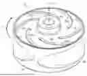
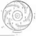
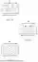
FIGS. 1A-1C provide three views of example impellers according to this disclosure, and FIGS. 1D-1E illustrate plan views of alternative embodiments. For consistency and convenience of cross-reference, elements common to more than one of FIGS. 1A-1C are numbered similarly.
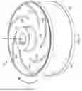
Impeller 100 is an enclosed impeller which comprises a shroud 105 comprising a substantially circular and planar section of a suitable material, such as steel, cast iron, aluminum, titanium, nickel or any other material which can handle the mechanical stresses and can be formed by casting, machining, or additive manufacturing. The configuration depicted and described may also be employed for a semi-open or vortex style impeller rather than the enclosed impeller 100 illustrated in FIGS. 1B and 1C.
The shroud 105 of the impeller 100 includes an outer perimeter 103 corresponding to the impeller trim diameter or outer diameter. Impeller 100 further comprises a hub 107, by which impeller 100 can be attached to the driveshaft of a motor or other source of rotary drive power of the centrifugal pump. While a pump case housing the impeller 100 is not shown in the figures, the structure depicted on the face of the impeller 100 in FIG. 1A and described in connection with FIGS. 1B and 1C can be used in a variety of centrifugal pump designs, including, without limitation, semi-open impeller pumps. The impeller 100 (or a semi-open variant) may be used with diffusor pumps of the type diagrammatically illustrated in FIG. 4 or volute case pumps of the type diagrammatically illustrated in FIGS. 3 and 3A. It should be noted that the intake opening (“inlet”) for the diffusor pump of FIG. 4 and the intake 303 of the volute case pump of FIGS. 3 and 3A is perpendicular to the face of the impeller 400, 300, while the discharge opening (“outlet,” e.g., outlet 304 in FIG. 3) provides a flow path somewhat tangential to the outer perimeter of the impeller 400, 300. It may also be noted that hub 107 in FIGS. 1A and 1C includes a keyed annular recess for receiving the drive shaft of a motor. Additionally, or alternatively, hub 107 can be an undriven bearing, and impeller 100 can be separately driven, such as by a magnetic drive, or as the rotor of an induction motor.
Impeller 100 is designed to be driven in a preferred direction of rotation 111. As shown in FIGS. 1B and 1C (where FIG. 1B is a casting of an impeller and FIG. 1C illustrates a machined impellers), impeller 100 further can further include a sidewall portion 104 extending perpendicular from the outer perimeter 103 of shroud 105. Sidewall portion 104 can include an open passageway for the exit and expulsion of pumped material. This passageway may include one or more single-vane, dual-vane, or multi-vane passageways, and may also include scrolled or tubular shaped passageways. In a single or multi-vaned impeller, the extension of sidewall portion 104 from an upper shroud to the lower shroud (not visible in FIGS. 1B and 1C) may be the result of a trimmed leading edge of a vane.
Instead of raised impeller vanes extending outward from a face of the shroud 105 parallel to the axis of rotation 115, the impeller 100 of the present disclosure has a plurality of inverted expulsion chambers 109a-109f which comprise grooves or troughs cut (e.g., by machining), cast, plate stamped, or otherwise formed as negative relief structures extending into the face of the shroud 105. When immersed in pumped media and rotated in the preferred direction of rotation 111, the inverted expulsion chambers 109a-109f create persistent pressure differentials along lines 110a-110f, forcing pumped media (including both liquids and solids) to be forcefully expelled radially outwards relative to hub 107 toward the outer perimeter 103. However, due to the absence of any raised protrusions from the face of the shroud 105, there are no surfaces upon which solids can catch in a way to drive a wedge between shroud 105 and other parts of the pump casing within which the shroud 105 is disposed. In this way, the problems of jamming, binding, or inefficiency created by running heterogeneous pumped media through a centrifugal pump with raised vanes are avoided.
As noted elsewhere in this disclosure, impeller 100 can be produced according to a plurality of manufacturing techniques, including without limitation, casting and machining. Accordingly, the profiles of inverted expulsion chambers 109a-109f may vary based upon the tooling used to create the impeller 100, as certain milling machines (for example, 3-axis computer numerical control (CNC) machines) may not be able to create the exact same relief profiles for inverted expulsion chambers 109a-109f as other milling machines (for example, 6-axis CNC machines).
As noted above, the impeller 100 may be employed as the impeller 300 in a volute case pump or as the impeller 400 in a diffusor pump, or an upper portion of the impeller 100 (without the sidewall portion 104 or the lower shroud) may be employed as the impeller in a semi-open pump. As described in further detail below, the number and configuration of the inverted expulsion chambers 109a-109f within the face of the shroud 105 may be varied for different applications, such as different types of centrifugal pumps.
While FIGS. 1A-1C depict embodiments according to this disclosure in which impeller 100 has six inverted expulsion chambers, the present disclosure should not be construed as being limited to any specific number of expulsion chambers. For example, as illustrated by FIG. 1D (three inverted expulsion chambers) or FIG. 1E (four inverted expulsion chambers), additional embodiments with greater or fewer numbers of expulsion chambers are possible and within the contemplated scope of this disclosure.
FIGS. 2 and 2A through 2F illustrate further aspects of inverted expulsion chambers according to various embodiments of this disclosure. For consistency and convenience of cross-reference, elements previously described or common to more than one of FIGS. 1A-1C and FIGS. 2 and 2A-2F are numbered similarly.
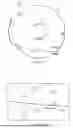
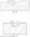
Referring to the illustrative example of FIGS. 2 and 2A, an inverted expulsion chamber cross-section perpendicular to the chamber path (line of pressure differentials) is illustrated. FIG. 2 is a simplified diagram of features of the impeller 100 for one line 110a of pressure differentials in FIG. 1A, and FIG. 2A is a sectional view of FIG. 2 taken at section line A-A. FIG. 2A thus illustrates the cross-section of an inverted expulsion chamber 109a at or near the outer perimeter 103. In certain embodiments, inverted expulsion chambers have a “backward leaning” geometry, where the line 110a along which a persistent pressure differential is created by the negative expulsion chamber becoming increasingly perpendicular to the radius of impeller 100 from an end of the inverted expulsion chamber 109a closest to the hub 107 toward an end of the inverted expulsion chamber 109a closest to the outer perimeter 103, and curving in a direction opposite to preferred direction of rotation 111 at points approaching the outer diameter of impeller 100. The aforementioned “backward leaning” geometry helps minimize hydraulic losses as pumped media is “swept up,” collected by, and expelled from each of the inverted expulsion chambers.
FIGS. 2 and 2A provide a non-limiting example cross-section for the inverted expulsion chambers according to various embodiments of this disclosure.
As shown in the figures, the inverted expulsion chamber comprises a trough point 201, which corresponds to the deepest point below the face of the shroud 105, a leading edge 203, and a trailing edge 205. As suggested by the name, the leading edge 203 comprises the “forward” portion of the inverted expulsion chamber relative to preferred direction of rotation 111, and trailing edge 205 comprises the “aft” or rearward portion of the inverted expulsion chamber relative to preferred direction of rotation 111. Depending on embodiments, leading edge 203 and trailing edge 205 can be symmetrical in terms of depth and slope relative to trough point 201, such as shown in FIG. 2B, 2C, and FIG. 2E.
FIG. 2B illustrates an inverted expulsion chamber with an “inverted zebra” or half-diamond shaped section in which the slope of leading edge 213 and trailing edge 215 is symmetrical relative to trough point 211. The “inverted zebra” cross section forms an equilateral triangle where the forward and back spans of the triangle are equal in length (where the forward span is closer to the direction of rotation of the impeller).
FIG. 2C illustrates an inverted expulsion chamber with a “half-orb” or semi-circular section, again with the change in depth of leading edge 223 and trailing edge 225 symmetrical relative to trough point 221. The “half orb” cross section forms a generally half or partially circular shape such as a semicircle or semioval (where the center of the circle or either foci of an oval are located along the top edge of the impeller, at the face of the upper shroud 105, or higher.
FIG. 2E is analogous to FIGS. 2B and 2C, except that the shape of the section is slightly irregular (neither triangular nor circular) despite the shape and/or the change in depth of leading edge 243 and trailing edge 245 being generally symmetrical relative to trough point 241. That is, FIG. 2E shows a “half orb” type expulsion chamber cross section with fillets applied to both the forward and back corners (where the semicircular or oval shapes meet the upper shroud surface). These added fillets allow for a smoother and more hydrodynamic flow into the chamber while minimizing recirculation and disruption of flow, which in turn reduces any negative effect on efficiency. The fillets are sized appropriately such that the original intention and shape of the cross section is not lost.
Additionally or alternatively, the cross section of the inverted expulsion chamber can be asymmetrical, with leading edge 233, 253 being shorter and steeper than trailing edge 235, 255 relative to the trough point 231, 251, such as shown in the “inverted airfoil” sections illustrated in FIG. 2D (with a regular profile) and FIG. 2F (with a slightly irregular profile). The regular “inverted airfoil” cross section of FIG. 2D forms a scalene triangle where the bottommost angle at the lower edge of the cross section is 90° or less and the backside or span of the triangle is also longer than the forward side (where the forward side is closer to the direction of rotation of the impeller). FIG. 2F shows an “inverted airfoil” type expulsion chamber cross section with fillets applied to three locations, including the forward and back corners (where the two sides of the triangular shapes meet the upper shroud surface) as well as at the lower point where the forward and back sides of the triangle meet. These added fillets allow for a smoother and more hydrodynamic flow into the chamber while minimizing recirculation and disruption of flow, which in turn reduces any negative effect on efficiency. The fillets are sized appropriately so that the original intention and shape of the cross section is not lost.
In some embodiments, multiple cross section geometries may be used in a single impeller. For example, different one of the inverted expulsion chambers may have different cross sectional geometries, or individual inverted expulsion chambers may have a cross sectional geometry that changes along the length of the relief feature. Moreover the depth(s) of the inverted expulsion chambers from one to another or along the length of a single inverted expulsion chamber. Any shape can be used as a cross section along the inverted expulsion chambers as long as the feature protrude or cut into the shroud surface without projecting above that surface and creating a potential pinch point.
An impeller for a centrifugal pump according to one embodiment of the present disclosure includes a shroud comprising a substantially planar circular section of material. A hub is disposed in the center of the shroud, where the hub is configured to connect the impeller to a driveshaft for rotation in a preferred direction. A plurality of inverted expulsion chambers are formed on an outer surface of the shroud, where each inverted expulsion chamber comprises a channel-shaped relief in the shroud extending from a location proximate to the center of the shroud towards an outer perimeter of the shroud.
Impellers according to various embodiments of this disclosure include impellers wherein the plurality of inverted expulsion chambers comprises less than six inverted expulsion chambers.
Impellers according to various embodiments of this disclosure include impellers wherein expulsion chambers of the plurality of expulsion chambers have a backward leaning geometry.
Impellers according to various embodiments of this disclosure include impellers wherein inverted expulsion chambers of the plurality of expulsion chambers have a cross-sectional geometry comprising a trough point, a leading edge and a trailing edge.
Impellers according to various embodiments of this disclosure include impellers, wherein the leading edges and trailing edges are symmetrical relative to the trough point.
Impellers according to various embodiments of this disclosure include impellers, wherein the leading edges and trailing edges are asymmetrical relative to the trough point.
Impellers according to various embodiments of this disclosure include impellers, wherein inverted expulsion chambers of the plurality inverted expulsion chambers embody more than one cross-sectional geometry.
Impellers according to various embodiments of this disclosure include impellers comprising at least one inverted expulsion chamber with more than one cross-sectional geometry, wherein the cross-sectional geometry varies along the inverted expulsion chamber.
Impellers according to various embodiments of this disclosure include impellers comprising one or more inverted expulsion chambers embodying a first cross-sectional geometry and one or more inverted expulsion chambers embodying a second cross-sectional geometry.
Although the present disclosure has been described with various embodiments, various changes and modifications may be suggested to one skilled in the art. It is intended that the present disclosure encompasses such changes and modifications as falling within the scope of the claims.
The present disclosure should not be read as implying that any particular element, step, or function is an essential element, step, or function that must be included in the scope of the claims. Moreover, the claims are not intended to invoke 35 U.S.C. § 112(f) unless the exact words “means for” are followed by a participle.
Claims
What is claimed is:1. An impeller for a centrifugal pump, the impeller comprising:
a shroud comprising a substantially planar circular section of material;
a hub disposed in the center of the shroud, the hub configured to connect the impeller to a driveshaft for rotation in a preferred direction; and
a plurality of inverted expulsion chambers, wherein each inverted expulsion chamber comprises a channel-shaped relief in the shroud extending from a location proximate to the center of the shroud toward an outer perimeter of the shroud.
2. The impeller of claim 1, wherein the plurality of inverted expulsion chambers comprises less than six inverted expulsion chambers.
3. The impeller of claim 1, wherein the plurality of inverted expulsion chambers comprises six or more inverted expulsion chambers.
4. The impeller of claim 1, wherein a cross section of each of the plurality of inverted expulsion chambers has a backward leaning geometry.
5. The impeller of claim 1, wherein a cross section of each of the plurality of inverted expulsion chambers comprises a trough point, a leading edge, and a trailing edge.
6. The impeller of claim 5, wherein the leading edges and trailing edges are symmetrical relative to the trough point.
7. The impeller of claim 5, wherein the leading edges and trailing edges are asymmetrical relative to the trough point.
8. The impeller of claim 1, wherein a cross section of two or more of the plurality of inverted expulsion chambers embody more than one cross-sectional geometry.
9. The impeller of claim 1, wherein at least one of the plurality of inverted expulsion chambers has a cross-sectional geometry that varies along a length of the at least one of the plurality of inverted expulsion chambers.
10. The impeller of claim 1, comprising a first one or more of the plurality of inverted expulsion chambers embodies a first cross-sectional geometry and a second one or more of the plurality of inverted expulsion chambers embodies a second cross-sectional geometry.
11. A centrifugal pump including the impeller of claim 1, wherein the shroud comprises a first shroud and wherein the impeller further comprises:
a second shroud; and
a sidewall portion extending between the first shroud and the second shroud,
wherein the centrifugal pump further comprises:
a casing within which the impeller is rotatably mounted, the casing including an intake opening and a discharge opening; and
a motor connected to rotate the impeller in the preferred direction.
12. A method of manufacturing an impeller for a centrifugal pump, the method comprising:
forming a shroud comprising a substantially planar circular section of material; and
disposing a hub in the center of the shroud, the hub configured to connect the impeller to a driveshaft for rotation in a preferred direction,
wherein an outer surface of the shroud includes a plurality of inverted expulsion chambers, wherein each inverted expulsion chamber comprises a channel-shaped relief in the shroud extending from a location proximate to the center of the shroud toward an outer perimeter of the shroud.
13. The method of claim 12, wherein the plurality of inverted expulsion chambers comprises less than six inverted expulsion chambers.
14. The method of claim 12, wherein the plurality of inverted expulsion chambers comprises six or more inverted expulsion chambers.
15. The method of claim 12, wherein a cross section of each of the plurality of inverted expulsion chambers has a backward leaning geometry.
16. The method of claim 12, wherein a cross section of each of the plurality of inverted expulsion chambers comprises a trough point, a leading edge, and a trailing edge.
17. The method of claim 16, wherein the leading edges and trailing edges are symmetrical relative to the trough point.
18. The method of claim 16, wherein the leading edges and trailing edges are asymmetrical relative to the trough point.
19. The method of claim 12, wherein a cross section of two or more of the plurality of inverted expulsion chambers embody more than one cross-sectional geometry.
20. The method of claim 12, wherein at least one of the plurality of inverted expulsion chambers has a cross-sectional geometry that varies along a length of the at least one of the plurality of inverted expulsion chambers.
Images & Drawings included:


Sources:
- United States Patent and Trademark Office - verify current appl. status at the USPTO↗
Recent applications in this class:
- » 20220356885 2022-11-10
Inducer for a submersible pump for pumping a slurry containing solids and viscous fluids and method of designing same - » 20160258442 2016-09-08
Boundary layer turbomachine