CONTROLLING A VARIABLE-SPEED HEATING, VENTILATION AND AIR-CONDITIONING SYSTEM USING A NON-COMMUNICATING TWO-STAGE THERMOSTAT
US20260098652A1
2026-04-09
19/338,996
2025-09-24
Smart Summary: A new way to control a heating, ventilation, and air conditioning (HVAC) system has been developed. It uses a two-stage thermostat that doesn't need to communicate with other devices. When the first signal is received, the system figures out how much heating or cooling it can provide. If both the first and second signals are received, the system can operate at its maximum capacity. Finally, when an off signal is sent, the HVAC system turns off completely. 🚀 TL;DR
Abstract:
A method is provided for controlling a variable-speed heat, ventilation and air conditioning (HVAC) system. The method includes, responsive to a first signal, determining a system capacity and providing the system capacity by the variable-speed HVAC system to a space, responsive to the first signal and a second signal, providing a system maximum capacity by the variable-speed HVAC system to the space and, responsive to an off signal, shutting off of the variable-speed HVAC system.
Applicant:
Interested in similar patents?
Get notified when new applications in this technology area are published.
Classification:
F24F11/63 » CPC main
Control or safety arrangements characterised by the type of control or by internal processing, e.g. using fuzzy logic, adaptive control or estimation of values Electronic processing
F24F2110/12 » CPC further
Control inputs relating to air properties; Temperature of the outside air
F24F2130/20 » CPC further
Control inputs relating to environmental factors not covered by group Sunlight
F24F2140/50 » CPC further
Control inputs relating to system states Load
Description
CROSS-REFERENCE TO RELATED APPLICATIONS
This application claims the benefit of U.S. provisional patent application Ser. No. 63/704,164, filed Oct. 7, 2024, the entire contents of which are incorporated herein by reference
BACKGROUND
The present disclosure relates to heating, ventilation and air conditioning (HVAC) systems and, more particularly, to controlling a variable-speed HVAC system using a non-communicating two-stage thermostat.
An increasing number of HVAC units are using variable-speed compressor technology to improve efficiency, comfort, and reliability. Variable-speed systems typically work by connecting a motor control drive to the compressor and then connecting the line input power from the utility to the drive. The drive uses frequency modulation to adjust power output and RPM of the compressor motor, enabling it to speed up or slow down according to the heating or cooling load in the home. This ability to modulate compressor capacity enables many of the advantages of variable-speed technology including improved efficiency and comfort. Other methods to control the power output and RPM of the compressor may also be employed.
It has been found that use of variable-speed compressor technology requires a system control capable of communicating additional information beyond a mere on/off signal to the compressor or motor control drive. Typically, the communicating capability is a part of a proprietary protocol; thus, increasing the number of components of the system and increasing costs. There is therefore a need for a system and method to control a variable-speed system at minimal cost.
BRIEF DESCRIPTION
According to an aspect of the disclosure, a method is provided for controlling a variable-speed heat, ventilation and air conditioning (HVAC) system. The method includes, responsive to a first signal, determining a system capacity and providing the system capacity by the variable-speed HVAC system to a space, responsive to the first signal and a second signal, providing a system maximum capacity by the variable-speed HVAC system to the space and, responsive to an off signal, shutting off of the variable-speed HVAC system.
In accordance with additional and/or alternative embodiments, the space includes a residential home.
In accordance with additional and/or alternative embodiments, the determining of the system capacity includes calculating a delivered capacity as a function of an instantaneous capacity delivered to the space over a predetermined time.
In accordance with additional and/or alternative embodiments, the delivered capacity is a function of the instantaneous capacity delivered to the space over a past predetermined amount of time and the delivered capacity is equal to a sum of a previously delivered capacity multiplied by n/m and the instantaneous capacity multiplied by (m−n)/m, where m is a time period and n is a fraction of the time period.
In accordance with additional and/or alternative embodiments, the instantaneous capacity is equal to a refrigerant massflow multiplied by a change in enthalpy, the refrigerant massflow is equal to refrigerant density as a function of suction pressure multiplied by compressor displacement multiplied by compressor RPMs and the change in enthalpy is equal to a difference between a vapor enthalpy as a function of discharge pressure and discharge temperature and a liquid enthalpy as a function of a liquid service valve temperature.
In accordance with additional and/or alternative embodiments, the providing of the system capacity includes at least one of adding an outside air temperature adjustment and adding a solar gain adjustment.
According to an aspect of the disclosure, a method is provided for controlling a variable-speed heat, ventilation and air conditioning (HVAC) system including a thermostat and a controller. The method includes determining, by the thermostat, whether to issue a first signal indicating first HVAC system operation, a second signal indicating second HVAC system operation and an off signal indicating HVAC system shut-off, issuing, based on determination results, one or more of the first signal, the second signal and the off signal to the controller by the thermostat, determining a system capacity and causing the variable-speed HVAC system to provide the system capacity to a space by the controller when the controller receives only the first signal, causing the variable-speed HVAC system to provide a system maximum capacity to the space by the controller when the controller receives the first and second signals and shutting off the variable-speed HVAC system by the controller when the controller receives the off signal.
In accordance with additional and/or alternative embodiments, the space includes a residential home.
In accordance with additional and/or alternative embodiments, the determining of whether to issue the first signal, the second signal and the off signal is based on a difference between an actual temperature of the space and a set point.
In accordance with additional and/or alternative embodiments, the determining of the system capacity includes calculating a delivered capacity as a function of an instantaneous capacity delivered to the space over a predetermined time by the controller and the delivered capacity is a function of the instantaneous capacity delivered to the space over a past predetermined amount of time.
In accordance with additional and/or alternative embodiments, the delivered capacity is equal to a sum of a previously delivered capacity multiplied by n/m and the instantaneous capacity multiplied by (m−n)/m, where m is a time period and n is a fraction of the time period.
In accordance with additional and/or alternative embodiments, the instantaneous capacity is equal to a refrigerant massflow multiplied by a change in enthalpy, the refrigerant massflow is equal to refrigerant density as a function of suction pressure multiplied by compressor displacement multiplied by compressor RPMs and the change in enthalpy is equal to a difference between a vapor enthalpy as a function of discharge pressure and discharge temperature and a liquid enthalpy as a function of a liquid service valve temperature.
In accordance with additional and/or alternative embodiments, the causing of the variable-speed HVAC system to provide the system capacity by the controller includes at least one of adding an outside air temperature adjustment based on outdoor air temperature readings of an outdoor unit sensor by the controller and adding a solar gain adjustment based on a time of day by the controller.
According to an aspect of the disclosure, a system is provided for controlling a variable-speed heat, ventilation and air conditioning (HVAC) system. The system includes a controller of the HVAC system and a thermostat. The thermostat is configured to determine whether to issue a first signal indicating low capacity HVAC system operation, a second signal indicating high capacity HVAC system operation and an off signal indicating HVAC system shut-off and to issue one or more of the first signal, the second signal and the off signal to the controller based on determination results. The controller is configured to determine a system capacity and cause the variable-speed HVAC system to provide the system capacity to a space upon receipt of only the first signal, cause the variable-speed HVAC system to provide a system maximum capacity to the space upon receipt of the first and second signals and shut off the variable-speed HVAC system upon receipt of the off signal.
In accordance with additional and/or alternative embodiments, the space includes a residential home.
In accordance with additional and/or alternative embodiments, the thermostat is configured to determine whether to issue the first signal, the second signal and the off signal based on a difference between an actual temperature of the space and a set point.
In accordance with additional and/or alternative embodiments, the controller is configured to determine the system capacity by calculating a delivered capacity as a function of an instantaneous capacity delivered to the space over a predetermined time and the delivered capacity is a function of the instantaneous capacity delivered to the space over a past predetermined amount of time.
In accordance with additional and/or alternative embodiments, the delivered capacity is equal to a sum of a previously delivered capacity multiplied by n/m and the instantaneous capacity multiplied by (m−n)/m, where m is a time period and n is a fraction of the time period.
In accordance with additional and/or alternative embodiments, the instantaneous capacity is equal to a refrigerant massflow multiplied by a change in enthalpy, the refrigerant massflow is equal to refrigerant density as a function of suction pressure multiplied by compressor displacement multiplied by compressor RPMs and the change in enthalpy is equal to a difference between a vapor enthalpy as a function of discharge pressure and discharge temperature and a liquid enthalpy as a function of a liquid service valve temperature.
In accordance with additional and/or alternative embodiments, the controller is configured to cause the variable-speed HVAC system to provide the system capacity by at least one of adding an outside air temperature adjustment based on outdoor air temperature readings of an outdoor unit sensor and adding a solar gain adjustment based on a time of day.
Additional features and advantages are realized through the techniques of the present disclosure. Other embodiments and aspects of the disclosure are described in detail herein and are considered a part of the claimed technical concept. For a better understanding of the disclosure with the advantages and the features, refer to the description and to the drawings.
BRIEF DESCRIPTION OF THE DRAWINGS
For a more complete understanding of this disclosure, reference is now made to the following brief description, taken in connection with the accompanying drawings and detailed description, wherein like reference numerals represent like parts:
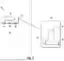
FIG. 1 is a schematic diagram of a system provided for controlling a variable-speed HVAC system that is configured to condition air within an interior space in accordance with embodiments;
FIG. 2 is a flow diagram illustrating a method for controlling a variable-speed HVAC system, such as the system of FIG. 1, in accordance with embodiments;
FIG. 3 is a flow diagram illustrating a process of the method of FIG. 2 in accordance with embodiments;
FIGS. 4A-4D are graphical depictions of an operation of the system of FIG. 1 executing the method of FIG. 2 in accordance with embodiments; and
FIGS. 5A and 5B are graphical depictions of DOE predictions of exemplary building load changes for one system size in accordance with embodiments.
DETAILED DESCRIPTION
Variable-speed systems are typically operated using a communicating wall control, such as a thermostat, that can command the system to increase or decrease capacity based on how close an actual temperature is to a commanded set point. Communicating wall controls are, however, much more expensive than non-communicating two-stage thermostats. Systems that are typically used with non-communicating two-stage thermostats often have two (or three) discrete stages-high and low- and are not fully variable.
Thus, as will be described below, a system is provided in which a capacity being delivered by a variable-speed system in an on-going basis is calculated and integrated and that the capacity is used when the system receives a low-stage signal. The system aggregates the capacity that is delivered to, for example, a home, over the course of a predetermined period of time (i.e., an hour) to determine a cooling load or a heating load on the home and then operates to match that capacity when receiving a stage one signal (indicating that house temperature is close to its set point). When the system received a stage two signal, the system would then operate at full capacity because the system cannot determine how far off the actual temperature is from the commanded set point. When stage two operation occurs, it pulls the integrated capacity calculation higher and, when the system is off, it will pull the integrated capacity calculation lower. The next stage one signal will then use the updated capacity calculation to again attempt to match the house load. Using this method will allow for fully variable, adaptive operation.
With reference to FIG. 1, a system 10 is provided for controlling a variable-speed HVAC system that is configured to condition air within an interior space, such as the inside of a residential home for example. The system 10 includes a two-stage system controller 12, such as a thermostat, that is disposed in communication with an HVAC unit 14. The HVAC unit 14 is illustrated as an outdoor unit, though it is to be understood that the HVAC unit 14 could be an indoor unit as well. For purposes of clarity and brevity, the following description will generally refer to the controller 12 as “thermostat 12” and will relate to the embodiments in which the HVAC unit 14 is an outdoor unit.
The thermostat 12 includes a processor 16 in communication with a memory 18 that can be, for example, a read only memory (ROM) and/or an electrically erasable programmable read only memory (EEPROM). The processor 16 is disposed in communication with a controller temperature sensor 20 and a display 21 that can be, for example, a liquid crystal display (LCD). The processor 16 and the memory 18 are configured to operate the HVAC unit 14 as described below. The controller temperature sensor 20 is configured to measure the actual air temperature within interior space 22, such as of a building or a residential home. The thermostat 12 is configured to transmit air conditioning signals based in part on system demands to heat or cool the interior space 22. The thermostat 12 can be disposed in wireless electrical communication with the HVAC unit 14 and/or in wired electrical communication with the HVAC unit 14.
The HVAC unit 14 includes a controller 24 in electrical communication with a variable speed compressor 26 and a unit temperature sensor 28. The controller 24 is configured to receive data from the unit temperature sensor 28, to receive the air conditioning signals from the thermostat 12 and transmit a speed signal to the variable speed compressor 26 based in part on the received air conditioning signals and the data. The variable speed compressor 26 is configured to operate at a plurality of speeds in a heating or cooling mode to deliver a compressed refrigerant. The unit temperature sensor 28 is configured to measure an ambient air temperature around the HVAC unit 14. It will be appreciated that the HVAC unit 14 may be provided as one or more of a split system, a variable refrigerant flow ductless unit, a heat pump, a packaged unit, a geothermal heat pump, etc. The unit temperature sensor 28 may be internal or external to the HVAC unit 14.
With reference to FIG. 2, a method 200 is provided for controlling a variable-speed HVAC system, such as the system 10 of FIG. 1, where the variable-speed HVAC system includes a thermostat and a controller, such as the thermostat 12 and the controller 24 of FIG. 1. As shown in FIG. 2, the method 200 includes determining, by the thermostat, whether to issue a first signal indicating low capacity HVAC system operation, a second signal indicating high capacity HVAC system operation and an off signal indicating HVAC system shut-off (block 201) and issuing, based on results of the determining of block 201, one or more of the first signal, the second signal and the off signal to the controller by the thermostat (block 202). The method 200 also includes determining a system capacity and causing the variable-speed HVAC system to provide the system capacity to a space, such as a building or a residential home, by the controller when the controller receives the first signal (block 203), causing the variable-speed HVAC system to provide a system maximum capacity to the space by the controller when the controller receives the first and second signals (block 206) and shutting off the variable-speed HVAC system by the controller when the controller receives the off signal (block 207). The causing of the variable-speed HVAC system to provide the system capacity by the controller of block 203 can include at least one of adding an outside air temperature (OAT) adjustment based on outdoor air temperature readings of an outdoor unit sensor, such as the unit temperature sensor 28 of FIG. 1, by the controller (block 204) and adding a solar gain adjustment based on a time of day by the controller (block 205).
In accordance with embodiments, the OAT adjustment can be equal to a predicted change to building loads that is caused by an OAT change and the solar gain adjustment can be equal to a predicted change to building loads that is caused by changes in solar gains (i.e., a prediction based on time of day or other factors).
The determining of whether to issue the first signal, the second signal and the off signal of block 201 can be based on a difference between an actual temperature of the space and a set point (it is to be understood that how “close” or “far” from the set point triggers each signal depends on, among other factors, the thermostat manufacturer). The determining of the system capacity of block 203 can include calculating a delivered capacity as a function of an instantaneous capacity delivered to the space over a predetermined time, such as an hour, for example, by the controller (block 2031) and the delivered capacity can be a function of the instantaneous capacity delivered to the space over a past predetermined amount of time, such as a previous hour, for example.
In accordance with embodiments, the delivered capacity can be equal to a sum of a previously delivered capacity (i.e., at t−1) multiplied by n/m and the instantaneous capacity multiplied by (m−n)/m, where m can represent some period of time, such as an hour or sixty minutes, and where n can represent some fraction of the period of time, such as fifty-nine minutes, such that n can be 59 and m can be 60, for example (60 is for minutes in an hour; this could be any time period based on what represents a prediction for a required capacity in the future and the 59 is used in conjunction with 60 for a numeric filter of past capacity for the required capacity in the future; other numeric filters could also be applied to similar effect). In accordance with further embodiments, the instantaneous capacity can be equal to a refrigerant massflow multiplied by a change in enthalpy, the refrigerant massflow can be equal to refrigerant density as a function of suction pressure multiplied by compressor displacement multiplied by compressor RPMs and the change in enthalpy can be equal to a difference between a vapor enthalpy as a function of discharge pressure and discharge temperature and a liquid enthalpy as a function of a liquid service valve temperature.
With continued reference to FIGS. 1 and 2 and with additional reference to FIG. 3, FIGS. 4A-4D and FIGS. 5A and 5B, an exemplary process of the system 10 of FIG. 1 and the method 200 of FIG. 2 will be described further.
As shown in FIG. 3, at block 301, it is determined whether only a “Y1” signal (i.e., the above-described first signal) is received and, if so, the HVAC system initially determines a delivered capacity at block 302. This delivered capacity can be calculated as being equal to a filtered instantaneous capacity delivered to a space, such as a home, over a past predetermined period of time, such as a previous hour, where for example:
delivered capacity = delivered capacity ( t - 1 ) * ( 59 / 60 ) + instantaneous capacity * ( 1 / 60 ) , instantaneous capacity = refrigerant massflow * change in enthalpy , refrigerant massflow = refrigerant density ⨯ compressor displacement ⨯ compressor RPM , refrigerant density = a function of suction pressure , change in enthalpy = vapor enthalpy - liquid enthalpy , vapor enthalpy = a function of discharge pressure and discharge temperature , and liquid enthalpy = a function of liquid service valve temperature .
Once the delivered capacity is determined at block 302, OAT and solar gain adjustments are executed at blocks 303 and 304, respectively, where the OAT adjustment can be equal to a predicted change to building loads that is caused by an OAT change and the solar gain adjustment can be equal to a predicted change to building loads that is caused by changes in solar gains (i.e., a prediction based on time of day or other factors). Next, at block 305, the HVAC system provides a predicted capacity, which can be equal to the delivered capacity and the OAT and solar gain adjustments.
At block 306, if the “Y1” signal is not the only signal that is received, it is determined whether the “Y1” signal (i.e., the above-described first signal) and a “Y2” signal (i.e., the above-described second signal) are received and, if so, the HVAC system provides a maximum system capacity at block 307. At block 308, it is determined whether an “Off” signal is received and, if so, the HVAC system is shut off at block 309.
As shown in FIG. 4A, during a first hour of operation of an HVAC system of a house, such as the system 10 of FIG. 1, stage 1 operation is 50% of a maximum HVAC system capacity and stage 2 operation is 100% of the maximum HVAC system capacity where the stage 1 operation occurs when only the “Y1” signal is issued and received by the thermostat 12 and the controller 24, respectively, and the stage 2 operation occurs when the “Y1” and the “Y2” signals are both issued and received by the thermostat 12 and the controller 24, respectively. During this hour, the controller 24 calculates a total cooling or heating supplied to the house and results of that calculation becomes an initial value for an integrated capacity. As shown in FIG. 4B, after the first hour, the controller 24 continually integrates capacity over a previous hour and the integrated capacity becomes stage 1 operation where stage 2 operation remains the maximum HVAC system capacity. As shown in FIG. 4C, the stage 1 operation will remain at a same capacity until stage 2 operation or shut-off time is commanded and thus changes the integrated capacity. In such cases, the stage 2 operation pulls the integrated capacity higher and the shut-off time pulls the integrated capacity lower. As shown in FIG. 4D, the stage 1 operation will eventually match a house load until conditions change, such as where OAT and solar gain adjustments are warranted.
As shown in FIG. 5A, Department of Energy (DOE) calculations predict a change of (400×Nominal Tonnage) Btu/hr per degree F. on exemplary building loads in heating and the integrated capacity can be increased or decreased by this amount as OAT changes for one system size. As shown in FIG. 5B, DOE calculations predict a change of (−260×Nominal Tonnage A2) Btu/hr per degree F. on exemplary building loads in heating and the integrated capacity can be increased or decreased by this amount as OAT changes for one system size.
Technical effects and benefits of the present disclosure are the provision of a method for controlling a variable-speed HVAC system using a non-communicating two-stage thermostat. Whereas typical systems operating with a non-communicating thermostat will operate in two (or sometimes three) discrete stages, the present disclosure allows for fully variable operation without the need for a more costly communicating wall control.
The corresponding structures, materials, acts, and equivalents of all means or step plus function elements in the claims below are intended to include any structure, material, or act for performing the function in combination with other claimed elements as specifically claimed. The description of the present disclosure has been presented for purposes of illustration and description, but is not intended to be exhaustive or limited to the technical concepts in the form disclosed. Many modifications and variations will be apparent to those of ordinary skill in the art without departing from the scope and spirit of the disclosure. The embodiments were chosen and described in order to best explain the principles of the disclosure and the practical application, and to enable others of ordinary skill in the art to understand the disclosure for various embodiments with various modifications as are suited to the particular use contemplated.
While the preferred embodiments to the disclosure have been described, it will be understood that those skilled in the art, both now and in the future, may make various improvements and enhancements which fall within the scope of the claims which follow. These claims should be construed to maintain the proper protection for the disclosure first described.
Claims
What is claimed is:1. A method for controlling a variable-speed heat, ventilation and air conditioning (HVAC) system, the method comprising:
responsive to a first signal, determining a system capacity and providing the system capacity by the variable-speed HVAC system to a space;
responsive to the first signal and a second signal, providing a system maximum capacity by the variable-speed HVAC system to the space; and
responsive to an off signal, shutting off of the variable-speed HVAC system.
2. The method according to claim 1, wherein the space comprises a residential home.
3. The method according to claim 1, wherein the determining of the system capacity comprises calculating a delivered capacity as a function of an instantaneous capacity delivered to the space over a predetermined time.
4. The method according to claim 3, wherein:
the delivered capacity is a function of the instantaneous capacity delivered to the space over a past predetermined amount of time, and
the delivered capacity is equal to a sum of a previously delivered capacity multiplied by n/m and the instantaneous capacity multiplied by (m−n)/m, where m is a time period and n is a fraction of the time period.
5. The method according to claim 3, wherein:
the instantaneous capacity is equal to a refrigerant massflow multiplied by a change in enthalpy,
the refrigerant massflow is equal to refrigerant density as a function of suction pressure multiplied by compressor displacement multiplied by compressor RPMs, and
the change in enthalpy is equal to a difference between a vapor enthalpy as a function of discharge pressure and discharge temperature and a liquid enthalpy as a function of a liquid service valve temperature.
6. The method according to claim 1, wherein the providing of the system capacity comprises at least one of adding an outside air temperature adjustment and adding a solar gain adjustment.
7. A method for controlling a variable-speed heat, ventilation and air conditioning (HVAC) system comprising a thermostat and a controller, the method comprising:
determining, by the thermostat, whether to issue:
a first signal indicating first HVAC system operation,
a second signal indicating second HVAC system operation, and
an off signal indicating HVAC system shut-off;
issuing, based on determination results, one or more of the first signal, the second signal and the off signal to the controller by the thermostat;
determining a system capacity and causing the variable-speed HVAC system to provide the system capacity to a space by the controller when the controller receives only the first signal;
causing the variable-speed HVAC system to provide a system maximum capacity to the space by the controller when the controller receives the first and second signals; and
shutting off the variable-speed HVAC system by the controller when the controller receives the off signal.
8. The method according to claim 7, wherein the space comprises a residential home.
9. The method according to claim 7, wherein the determining of whether to issue the first signal, the second signal and the off signal is based on a difference between an actual temperature of the space and a set point.
10. The method according to claim 9, wherein:
the determining of the system capacity comprises calculating a delivered capacity as a function of an instantaneous capacity delivered to the space over a predetermined time by the controller, and
the delivered capacity is a function of the instantaneous capacity delivered to the space over a past predetermined amount of time.
11. The method according to claim 10, wherein the delivered capacity is equal to a sum of a previously delivered capacity multiplied by n/m and the instantaneous capacity multiplied by (m−n)/m, where m is a time period and n is a fraction of the time period.
12. The method according to claim 10, wherein:
the instantaneous capacity is equal to a refrigerant massflow multiplied by a change in enthalpy,
the refrigerant massflow is equal to refrigerant density as a function of suction pressure multiplied by compressor displacement multiplied by compressor RPMs, and
the change in enthalpy is equal to a difference between a vapor enthalpy as a function of discharge pressure and discharge temperature and a liquid enthalpy as a function of a liquid service valve temperature.
13. The method according to claim 7, wherein the causing of the variable-speed HVAC system to provide the system capacity by the controller comprises at least one of adding an outside air temperature adjustment based on outdoor air temperature readings of an outdoor unit sensor by the controller and adding a solar gain adjustment based on a time of day by the controller.
14. A system for controlling a variable-speed heat, ventilation and air conditioning (HVAC) system, the system comprising:
a controller of the HVAC system; and
a thermostat configured to determine whether to issue a first signal indicating low capacity HVAC system operation, a second signal indicating high capacity HVAC system operation and an off signal indicating HVAC system shut-off and to issue one or more of the first signal, the second signal and the off signal to the controller based on determination results,
the controller being configured to:
determine a system capacity and cause the variable-speed HVAC system to provide the system capacity to a space upon receipt of only the first signal;
cause the variable-speed HVAC system to provide a system maximum capacity to the space upon receipt of the first and second signals; and
shut off the variable-speed HVAC system upon receipt of the off signal.
15. The system according to claim 14, wherein the space comprises a residential home.
16. The system according to claim 14, wherein the thermostat is configured to determine whether to issue the first signal, the second signal and the off signal based on a difference between an actual temperature of the space and a set point.
17. The system according to claim 14, wherein:
the controller is configured to determine the system capacity by calculating a delivered capacity as a function of an instantaneous capacity delivered to the space over a predetermined time, and
the delivered capacity is a function of the instantaneous capacity delivered to the space over a past predetermined amount of time.
18. The system according to claim 17, wherein the delivered capacity is equal to a sum of a previously delivered capacity multiplied by n/m and the instantaneous capacity multiplied by (m−n)/m, where m is a time period and n is a fraction of the time period.
19. The system according to claim 17, wherein:
the instantaneous capacity is equal to a refrigerant massflow multiplied by a change in enthalpy,
the refrigerant massflow is equal to refrigerant density as a function of suction pressure multiplied by compressor displacement multiplied by compressor RPMs, and
the change in enthalpy is equal to a difference between a vapor enthalpy as a function of discharge pressure and discharge temperature and a liquid enthalpy as a function of a liquid service valve temperature.
20. The system according to claim 14, wherein the controller is configured to cause the variable-speed HVAC system to provide the system capacity by at least one of adding an outside air temperature adjustment based on outdoor air temperature readings of an outdoor unit sensor and adding a solar gain adjustment based on a time of day.
Images & Drawings included:


Sources:
- United States Patent and Trademark Office - verify current appl. status at the USPTO↗
Recent applications in this class:
- » 20260085850 2026-03-26
AIR-CONDITIONING SYSTEM, CONTROL METHOD, AND RECORDING MEDIUM - » 20260085849 2026-03-26
TEMPERATURE CONTROL METHOD, ELECTRONIC DEVICE, AND STORAGE MEDIUM - » 20260055915 2026-02-26
SYSTEM FOR CONTROLLING HEATING VENTILATION AND AIR CONDITIONING (HVAC) SYSTEMS - » 20260055914 2026-02-26
BUILDING MANAGEMENT SYSTEM WITH DIGITAL MODULES FOR SENSORS AND CONTROLLED DEVICES - » 20260036323 2026-02-05
INDOOR CAMERA OR OTHER MICROPHONE DETERMINING OCCUPANCY TO ADJUST A THERMOSTAT - » 20260036322 2026-02-05
Model-Based Ambient Temperature Estimation for Control of an HVAC System - » 20260036321 2026-02-05
MANAGEMENT SYSTEM, METHOD AND RECORDING MEDIUM - » 20260036320 2026-02-05
SYSTEM FOR CLEANING, ZEROING, AND PREVENTING AIR POLLUTION IN INDOOR SPACE - » 20260029148 2026-01-29
SMART HVAC ROOFTOP UNITS WITH INTEGRATED AI AND THERMAL IMAGING FOR ENHANCED OPERATIONAL CONTROL - » 20260022852 2026-01-22
METHOD FOR DYNAMICALLY REDUCING MEMORY FREQUENCY OF AIR CONDITIONER, AIR CONDITIONER, AND STORAGE MEDIUM