VENTILATION SYSTEM
US20260098656A1
2026-04-09
19/351,769
2025-10-07
Smart Summary: A backdraft damper is part of a ventilation fan system that helps control airflow. It has a main body with two ends and an inner space. Inside this space, there is a door that can open and close. When the door is closed, it sits tightly against the inner wall, and when it's open, it allows air to flow freely. Additionally, a block inside the main body helps create pressure that makes the door move, ensuring it works effectively when the fan is on. 🚀 TL;DR
Abstract:
A backdraft damper for a ventilation fan assembly, the backdraft damper having a main body having a wall defining an inner surface, an outer surface, a first open end and a second open end. An interior space is defined by the main body wall inner surface. A damper door is rotationally coupled to the main body wall and located within the interior space. The damper door defines a perimeter edge and the damper door is configured to rotate between (i) a closed position, in which the perimeter edge is located adjacent to the main body inner surface, and (ii) an open position in which a majority of the perimeter edge is not adjacent to the main body inner surface. A block extends from the main body wall inner surface into the interior space adjacent to the damper door perimeter edge when the damper door is in the closed position and, during operation of the fan assembly, creates an area of high pressure which creates a torque on the damper door.
Applicant:
Interested in similar patents?
Get notified when new applications in this technology area are published.
Classification:
F24F13/14 » CPC main
Details common to, or for air-conditioning, air-humidification, ventilation or use of air currents for screening; Air-flow control members, e.g. louvres, grilles, flaps or guide plates movable, e.g. dampers built up of tilting members, e.g. louvre
Description
CROSS-REFERENCE TO RELATED APPLICATIONS
This application claims the benefit of Provisional Application No. 63/704,588, filed Oct. 8, 2024, which is incorporated in its entirety herein by reference and made a part hereof.
BACKGROUND
The present disclosure relates, generally, to a ventilation fan. Ventilating fans, such as those typically installed in bathrooms, draw air from within an area and pass the exhausted air out to another location, such as through a vent in the gable or roof of a home or other building structure. Ventilation fans often have a housing configured to be positioned within a building structure adjacent an aperture in a wall or ceiling and are often attached to wall or ceiling joists to position the ventilation fan adjacent to, and aligned with the wall or ceiling aperture.
Certain ventilating exhaust fans include backdraft dampers positioned at an outlet of the housing outlet to allow the outward airflow through the housing outlet while minimizing or preventing airflow in the reverse direction. Although backdraft dampers can mitigate backdraft through the housing outlet, often at least some portion of the damper assembly partially obstructs the housing outlet reducing the effective cross-sectional area of the housing outlet. The reduced cross-sectional area of the housing outlet reduces the efficiently of the exhaust fans by obstructing the outward airflow. In addition, the backdraft damper can create airflow disruptions that can reduce airflow and efficiency of the ventilation fan. These airflow disruptions can also create unwanted audible noise and/or vibration.
Additional features of the present disclosure will become apparent to those skilled in the art upon consideration of illustrative embodiments exemplifying certain modes of carrying out the disclosure as presently perceived.
BRIEF DESCRIPTIONS OF THE DRAWINGS
The accompanying drawings, which are included to provide further understanding and are incorporated in and constitute a part of this specification, illustrate disclosed embodiments and together with the description serve to explain the principles of the disclosed embodiments. In the drawings:
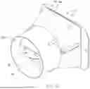
FIG. 1A is a perspective view of a backdraft damper according to one embodiment of the disclosure as viewed from the downstream end.
FIG. 1B is a perspective view of the backdraft damper of FIG. 1A as viewed from the upstream end.
FIG. 1C is a plan view of the backdraft damper of FIG. 1A as viewed from the upstream end.
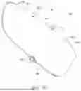
FIG. 2A is a perspective view of a damper door of the backdraft damper of FIG. 1A.
FIG. 2B is an alternative perspective view of the damper door of FIG. 2A.
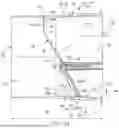
FIG. 3A is a cross-sectional view of the backdraft damper of FIG. 1A with the damper door in a closed position.
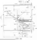
FIG. 3B is a cross-sectional view of the backdraft damper of FIG. 3A with the damper door in a partially opened position.
FIG. 3C is a cross-sectional view of the backdraft damper of FIG. 3A with the damper door in a fully opened position.
DETAILED DESCRIPTION
One embodiment of a ventilation fan assembly 10 of the present disclosure is depicted in the Figures. Some embodiments of the ventilation fan assembly 10 can include several components and devices that can perform various functions. In the depicted embodiment, the ventilation fan assembly 10 has a housing 12 comprised of a first sidewall 14, a second sidewall 16, a third sidewall 18, and a fourth sidewall 20 and a bottom wall 22 collectively defining an interior space 24 of the housing 12. The first, second, third and fourth sidewalls 14, 16, 18, 20 define a housing inlet 26 through which air can be drawn from the surrounding environment. An outlet aperture 28 is defined in one of the first, second, third and fourth sidewalls 14, 16, 18, 20 or the bottom wall 22 of the housing 12 to direct outflow of air from the housing 12. A blower assembly (not depicted) can be located within the interior space 24 of the housing 12 to move air through the housing 12.
The housing 12 can be constructed of any material which can provide self-supporting structural support to the ventilation fan assembly 10, while also being able to accommodate varying temperatures and environmental conditions (e.g., to withstand any heat radiated and/or conducted from the motor, or other components). In some embodiments, the housing 12 can be formed of sheet material comprising a relatively high melting temperature. In some embodiments, the housing 12 can be formed from a sheet metal, including, but not limited to an aluminum-based metal, a steel or iron-based metal, a zinc-based metal such as galvanized steel, or a nickel and tin-based metal. The housing first, second, third and fourth sidewalls 14, 16, 18, 20 and the bottom wall 22 can be formed from sheets of metal (e.g., galvanized steel), and joined using a variety of conventional joining techniques include welding, soldering, friction-bonding, crimping, riveting, and screw-attachment and the like. In some embodiments, one or more conventional flanges or tabs can be including in any one of the sidewalls 14, 16, 18, 20 and the bottom wall 22 to facilitate connection of each of the sidewalls 14, 16, 18, 20 and the bottom wall 22 to one or more adjacent ones of the sidewalls 14, 16, 18, 20 and the bottom wall 22.
In some other embodiments, the housing 12 can be formed from a polymer-based material, including, but not limited to injection molded polymers, thermo-formed polymers, thermosetting polymers, or any other suitable material. Some embodiments can include a housing 12 that comprises a wood-based product, such as wood, or particle-board or wood laminate. In some other embodiments, the housing can comprise a ceramic or ceramic-composite based product. In some further embodiments, the housing 12 can comprise a glass-fiber or other fiber-reinforced laminate material.
The housing 12 can be formed into any shape, including, but not limited to, a rectangular box-like shape, an oval shape, a hemispherical shape, a spherical shape, a pyramidal shape, or any other shape. The housing 12 can form a base or a similar support structure of the ventilation fan assembly 10. Further, in some embodiments, the housing 12 can provide points and areas of attachment for other components of the ventilation fan assembly 10, as described in further detail below.
A backdraft damper assembly 30 (alternately referenced herein simply as “damper” for simplicity) is situated adjacent to, and optionally secured to, the housing at or adjacent to the outlet aperture 28. The damper 30 can have a main body 32 comprising a wall 34 defining or approximating a cylinder having a first open end 36 (alternately referenced herein as the “upstream end 36”) for receiving airflow from the fan housing 12 and an opposing second open end 38 (alternately referenced herein as the “downstream end 38”) through which airflow exits the damper 30. The wall 34 defines an inner surface 34a and an outer surface 34b. The inner surface 34a of the wall 34 defines an interior space 40 of the damper 30, which acts as a flow channel 42 during operating of the ventilation fan assembly 10 or during unintended airflow due to wind, changes in air pressure, etc.
The wall inner surface 34a can define any desired shape and can define any number of different shapes along a length 44 of the damper between the first open end 36 and the second open end 38. In one example, the wall inner surface 34a of the damper 30 can define a substantially tubular-shape or pipe-shape. In another example, the wall inner surface 34a of the damper 30 can define a substantially rectangular, square, circular, triangular, octagonal, other polygonal shapes or a combination of any of the above.
In one embodiment, the first open end 36 can define a first shape and the second open end 38 can define a second shape different from the first shape of the first open end 36. In the depicted example, the first open end 36 defines a substantially rectangular shape to roughly correspond with a rectangular shape of the fan housing outlet aperture 28 and the second open end 38 is substantially circular to facilitate easy connection to round ducting to route air flow from the damper 30 to an exterior of the building structure. In yet another embodiment, shapes of the first and second open ends 36, 38 can be the same as one another. In other embodiments, the shapes of the first and second open ends 36, 38 can be any shape desired. When the shapes of the first and second open ends 36, 38 are different from one another or the sizes differ, then a portion of the main body wall 34 must provide a transition region 46 to facilitate transition of size and/or shape between the first open end 36 to the second open end 38.
In one embodiment, the main body wall inner surface 34a is substantially smooth (other than block 80 discussed below) from the first open end 36 to the second open end 38 and without abrupt intrusion into the damper interior space 40 so as to limit flow disturbances and approximate laminar flow through the flow channel 42 during operation of the ventilation fan assembly. In one embodiment, the main body wall inner surface 34a defines two small stops 34c against which a damper door 50 (discussed below) can rest in a closed position.
A damper door 50 (sometimes referenced herein as “door” for simplicity) is rotatable mounted to the main body 32 within the main body interior space 40 to rotate between and open position (e.g. FIG. 3C) to allow flow through the flow channel 42 and a closed position (e.g. FIG. 3A), in which the damper door 50 contacts the stops 34c, in order to substantially obstruct backflow through the flow channel 42. The damper door 50 comprises a door plate 52 and a tail plate 54 extending from an edge of the door plate 52. The damper door 50 has a first side 50a and a second side 50b and defines a perimeter edge 50c extending around the perimeter of the door plate 52 and tail plate 54. In the depicted embodiment, the door plate 52 is substantially flat, but variations therefrom are contemplated. In the depicted embodiment, the tail plate 54 is likewise substantially flat, with possible variations, and extends from the door plate 52 at an angle as shown. In one embodiment, that angle can be in the range of 25 degrees to 35 degrees. Two pins 56 extend from opposing sides of the perimeter edge 50c to facilitate rotational engagement with the main body 32 and define an axis of rotation 58 of the damper door 50, which divides the damper door 50 into an upper section 50d and a lower section 50e. In one embodiment, each of the two pins 56 rotationally engage a respective boss 48 defined on the wall 34 of the main body 32. The designations “upper” and “lower” refer to the positions of the door section 50d,e when the damper door is in a closed position without operation of the ventilation fan assembly 10 (e.g. FIG. 3A).
The damper door 50 further has a plurality of fins 60 extending from the damper door second side 50b. In one embodiment, each of the plurality of fins 60 extends perpendicularly from the damper door second side 50b and runs along the damper door second side 50b in a direction perpendicular to the damper door rotational axis 58. In the depicted embodiment, each of the plurality of fins 60 extends only along the damper door lower section 50e from approximately the damper door rotational axis 58 to the damper door perimeter edge 50c. However, variations are contemplated in which one or more of the fins 60 does not extend to the damper door rotational axis 58 and/or the damper door perimeter edge 50c. The weight of the plurality of fins 60 makes the damper door lower section 50e heavier than the damper door upper section 50d such that the weight of the damper door lower section 50e will cause the damper door 50 to be rotationally biased to place the damper door 50 in the closed position and will stay in the closed position absent sufficient airflow causing the damper door 50 to rotate out of the closed position. Additionally, during operation of the ventilation fan assembly, the plurality of fins 60 tends to streamline airflow passing over the fins 60.
During operation of the ventilation fan assembly 10, airflow Fis generated by the ventilation fan assembly 10 and directed out of the housing outlet aperture 28 to the damper 30, and received into the first open end 36, which is configured to be located adjacent to the housing outlet aperture 28 when assembled. When the first open end 36 of the damper 30 receives the airflow F, the first open end 36 becoming the upstream end of the damper 30 and the second open end of the damper 30 becomes the downstream end of the damper 30. As discussed above, the damper door 50 is configured and arranged such that the lower section 50e is biased downward by gravity creating a torque on the damper door 50 that would appear clockwise (but is not depicted) in FIGS. 3A-3C. However, the damper door 50 is configured and arranged such that when the damper door 50 is in the closed position (e.g. against the stops 34c in FIG. 3A), the force or the airflow F on the damper door 50 creates a greater opposing torque T that rotates the damper door out of the closed position and allows the airflow F to spill around the damper door perimeter edge 50c. The damper door 50 can be configured and arranged in any known manner to cause the airflow F to create the torque necessary to move the damper door 50 from the closed position.
A block 80 protrudes from the inner surface 34a of the main body wall 34 into the flow channel 42 to intentionally provide an abrupt intrusion into the flow channel 42. In one embodiment, the bock 80 can be formed integrally with the main body wall 34, but can, in other embodiments, be a discrete part attached to the main body wall inner side 34a. In the depicted embodiment, the block 80 is a rectangular box shape having a flat leading side 82a, a flat trailing side 82b, a flat top side 82c and a flat bottom side 82d. The terms “leading” and “trailing” designate the location of the sides with respect to the airflow F, for which the damper 30 is configured. The block 80 also has two ends 84 of equal size and shape. The distance between the two ends 84 defines a block length 86. The leading side 82a defines a height 88 that is equal to the height 88 of the trailing side 82b. A depth 90 is defined between the leading side and the trailing side. Other shapes of the block 80 are contemplated consistent with the principles and objectives described herein.
As the damper door 50 rotates toward the open position, the airflow F generates areas of higher and lower pressure around the damper door 50 consistent with known aerodynamic principles. FIG. 3B depicts the damper 30 with the damper door 50 in a half open position. Depending upon the flowrate of the airflow F being produced by the ventilation fan assembly 10, the airflow F might not be sufficient to place the damper door 50 in a horizontal, or nearly horizontal, position, which would minimize flow turbulence created by the damper door 50 and maximize flowrate for the given power consumed by the blower. This issue can occur in situations where a one-size-fits-all damper is employed with multiple fan designs and/or where a fan can be run at different flow rates.
In one embodiment, the block 80 is situated so that the leading side 82a is located at approximately the bottom stop 34c. In other embodiments not having a stop 34c, the block leading side 82a is located at a resting place 92 where the damper door perimeter edge 50c rests when the damper door 50 perimeter edge 50c is as close to the wall inner surface 34a as it gets. Once the damper door 50 opens slightly from the closed position, the airflow F encounters the block 80 and creates a zone of high pressure 100 at the block leading side 82a, consistent with known aerodynamic principles. The size and intensity of the zone of high pressure 100 increases as the flow rate over the block 80 increases. As can be seen in FIG. 3B, a zone of high pressure adjacent to the block leading side 82a will encounter and act on the damper door lower section 50e supplementing the torque T and tending to rotate the damper door 50 toward the fully open position depicted in FIG. 3C.
It will be recognized that the size and magnitude of the zone of high pressure 100 (and the resulting supplemental torque T) will depend, among other things, on the length 86, height 88 and depth 90 of the block 80. Different sized (i.e. length 86, height 88 and/or depth 90) blocks 80 may be used in the same damper 30 for when the ventilation fan assembly 10 will be run at different flow rates. For example, if the damper 30 were receiving a flow rate of 60 CFM (“cubic feet per minute”), it would have a smaller high pressure zone 100, and thus smaller supplemental torque T, than if it were receiving a flow rate of 80 CFM. Therefore, to achieve the same size high pressure zone 100 and supplemental torque T, the block 80 would need to larger when receiving 60 CFM than when receiving 80 CFM. In one embodiment, then, the damper 30 can be provided with multiple different sized blocks 80 as a kit to allow the user to select which of the blocks 80 is appropriate for the flow rate at which the ventilation fan assembly 10 will be operated.
In one embodiment, the block 80 is constructed from a flexible, closed cell foam adhered to the main body wall 34 with an adhesive. Using a flexible foam material allows the fins 60 to slightly deform the block 80 when the damper 30 is in the closed position, which allows the block 80 to be located as close to the resting place 92 as possible. This keeps the location of the high pressure zone 100 as close as possible to the damper first open end 36, which increases the magnitude of the supplemental torque T. The high pressure zone 100 can, however, be effectively created by constructing the block 80 from any number of other materials. In one embodiment, the material selected for the block 80 should be sufficiently rigid to resist deformation under the flow rate for which it is intended. In other embodiments, however, the block is constructed of a material that will deform under one or more flow rates for which it is configured such that the aerodynamic profile of the block 80 can change with the flow rate at which the ventilation fan assembly 10 is operated.
As indicated above, the depicted embodiment shows the block leading side 82a at the stop 34c, but can be located at the resting place 92 where no stop 34c exists. The remainder of the block 80 extends downstream from the stop 34c (or resting place 92) toward the damper second open end 38. In other embodiments, the block can be located downstream of the stop 34c (or resting place 92). In other embodiments, the stop 34c could be enlarged to constitute the block such that the same element perform both the function of the block 80 and the stop 34c.
It should be noted that the various components and features described above can be combined in a variety of ways, so as to provide other non-illustrated embodiments within the scope of the disclosure. As such, it is to be understood that the disclosure is not limited in its application to the details of construction and parts illustrated in the accompanying drawings and described hereinabove. The disclosure is capable of other embodiments and of being practiced in various ways. It is also to be understood that the phraseology or terminology used herein is for the purpose of description and not limitation.
Although the present disclosure has been described in the foregoing description by way of illustrative embodiments thereof, these embodiments can be modified at will, without departing from the spirit, scope, and nature of the subject disclosed.
Headings and subheadings, if any, are used for convenience only and do not limit the invention. The word exemplary is used to mean serving as an example or illustration. To the extent that the term include, have, or the like is used, such term is intended to be inclusive in a manner similar to the term comprise as comprise is interpreted when employed as a transitional word in a claim. Relational terms such as first and second and the like may be used to distinguish one entity or action from another without necessarily requiring or implying any actual such relationship or order between such entities or actions.
Phrases such as an aspect, the aspect, another aspect, some aspects, one or more aspects, an implementation, the implementation, another implementation, some implementations, one or more implementations, an embodiment, the embodiment, another embodiment, some embodiments, one or more embodiments, a configuration, the configuration, another configuration, some configurations, one or more configurations, the subject technology, the disclosure, the present disclosure, other variations thereof and alike are for convenience and do not imply that a disclosure relating to such phrase(s) is essential to the subject technology or that such disclosure applies to all configurations of the subject technology. A disclosure relating to such phrase(s) may apply to all configurations, or one or more configurations. A disclosure relating to such phrase(s) may provide one or more examples. A phrase such as an aspect or some aspects may refer to one or more aspects and vice versa, and this applies similarly to other foregoing phrases.
All numbers and ranges disclosed above may vary by some amount. Whenever a numerical range with a lower limit and an upper limit is disclosed, any number and any included range falling within the range are specifically disclosed. In particular, every range of values (of the form, “from about a to about b,” or, equivalently, “from approximately a to b,” or, equivalently, “from approximately a-b”) disclosed herein is to be understood to set forth every number and range encompassed within the broader range of values. In addition, the terms in the claims have their plain, ordinary meaning unless otherwise explicitly and clearly defined by the patentee. Moreover, the indefinite articles “a” or “an,” as used in the claims, are defined herein to mean one or more than one of the element that it introduces. If there is any conflict in the usages of a word or term in this specification and one or more patent or other documents that may be incorporated herein by reference, the definitions that are consistent with this specification should be adopted.
A phrase “at least one of” preceding a series of items, with the terms “and” or “or” to separate any of the items, modifies the list as a whole, rather than each member of the list. The phrase “at least one of” does not require selection of at least one item; rather, the phrase allows a meaning that includes at least one of any one of the items, and/or at least one of any combination of the items, and/or at least one of each of the items. By way of example, each of the phrases “at least one of A, B, and C” or “at least one of A, B, or C” refers to only A, only B, or only C; any combination of A, B, and C; and/or at least one of each of A, B, and C.
In one aspect, a term coupled or the like may refer to being directly coupled. In another aspect, a term coupled or the like may refer to being indirectly coupled. Terms such as top, bottom, front, rear, side, horizontal, vertical, and the like refer to an arbitrary frame of reference, rather than to the ordinary gravitational frame of reference. Thus, such a term may extend upwardly, downwardly, diagonally, or horizontally in a gravitational frame of reference.
The title, background, brief description of the drawings, abstract, and drawings are hereby incorporated into the disclosure and are provided as illustrative examples of the disclosure, not as restrictive descriptions. It is submitted with the understanding that they will not be used to limit the scope or meaning of the claims. In addition, in the detailed description, it can be seen that the description provides illustrative examples and the various features are grouped together in various implementations for the purpose of streamlining the disclosure. The method of disclosure is not to be interpreted as reflecting an intention that the claimed subject matter requires more features than are expressly recited in each claim. Rather, as the claims reflect, inventive subject matter lies in less than all features of a single disclosed configuration or operation. The claims are hereby incorporated into the detailed description, with each claim standing on its own as a separately claimed subject matter.
The use of the terms “a” and “an” and “the” and “said” and similar references in the context of describing the invention (especially in the context of the following claims) are to be construed to cover both the singular and the plural, unless otherwise indicated herein or clearly contradicted by context. An element proceeded by “a,” “an,” “the,” or “said” does not, without further constraints, preclude the existence of additional same elements. Recitation of ranges of values herein are merely intended to serve as a shorthand method of referring individually to each separate value falling within the range, unless otherwise indicated herein, and each separate value is incorporated into the specification as if it were individually recited herein. All methods described herein can be performed in any suitable order unless otherwise indicated herein or otherwise clearly contradicted by context. The use of any and all examples, or exemplary language (e.g., “such as”) provided herein, is intended merely to better illuminate the disclosure and does not pose a limitation on the scope of the disclosure unless otherwise claimed. No language in the specification should be construed as indicating any non-claimed element as essential to the practice of the disclosure.
Numerous modifications to the present disclosure will be apparent to those skilled in the art in view of the foregoing description. Preferred embodiments of this disclosure are described herein, including the best mode known to the inventors for carrying out the disclosure. It should be understood that the illustrated embodiments are exemplary only, and should not be taken as limiting the scope of the disclosure.
Claims
1. A ventilation fan assembly comprising:
a housing having at least one sidewall defining an interior space, an inlet opening into the interior space, and an outlet aperture spaced apart from the inlet, wherein the housing is configured to contain a blower assembly in the interior space;
a backdraft damper configured to be coupled to the housing adjacent to the outlet aperture, the backdraft damper comprising,
a main body having a wall defining an inner surface, an outer surface, a first open end and a second open end;
an interior space defined by the main body wall inner surface;
a damper door rotationally coupled to the main body wall and located within the interior space;
the damper door defining a perimeter edge and configured to rotate between (i) a closed position, in which the perimeter edge is located adjacent to the main body inner surface, and (ii) an open position in which a majority of the perimeter edge is not adjacent to the main body inner surface;
wherein the damper door is rotationally biased to the closed position;
a block extending from the main body wall inner surface into the interior space adjacent to the damper door perimeter edge when the damper door is in the closed position.
2. The ventilation fan of claim 1, wherein the block is located at the gravitational bottom of the main body wall inner surface.
3. The ventilation fan of claim 1, wherein the block is configured to create an area of high pressure when air flows through the interior space.
4. The ventilation fan of claim 3, wherein the area of high pressure creates a torque on the damper door opposite of a torque created by gravity.
5. The ventilation fan of claim 1, where the block defines a rectangular cross section.
6. The ventilation fan of claim 1, wherein the block is constructed of a rigid, closed cell foam.
7. The ventilation fan of claim 1, wherein the block is constructed of a non-rigid material.
8. A backdraft damper for a ventilation fan assembly, the backdraft damper comprising:
a main body having a wall defining an inner surface, an outer surface, a first open end and a second open end;
an interior space defined by the main body wall inner surface;
a damper door rotationally coupled to the main body wall and located within the interior space;
the damper door defining a perimeter edge and configured to rotate between (i) a closed position, in which the perimeter edge is located adjacent to the main body inner surface, and (ii) an open position in which a majority of the perimeter edge is not adjacent to the main body inner surface;
wherein the damper door is rotationally biased to the closed position;
a block extending from the main body wall inner surface into the interior space adjacent to the damper door perimeter edge when the damper door is in the closed position.
9. The backdraft damper of claim 8, wherein the block is located at the gravitational bottom of the main body wall inner surface.
10. The backdraft damper of claim 8, wherein the block is configured to create an area of high pressure when air flows through the interior space.
11. The backdraft damper of claim 10, wherein the area of high pressure creates a torque on the damper door opposite of a torque created by gravity.
Images & Drawings included:


Sources:
- United States Patent and Trademark Office - verify current appl. status at the USPTO↗
Similar patent applications:
- » 20100101514
Positive crankcase ventilation system, cylinder head used for positive crankcase ventilation system, internal combustion engine including positive crankcase ventilation system, and positive crankcase ventilation method - » 20200061681
Ventilation system, a method of operating a ventilation system, a duct section to be used in a ventilation system, and the use of such duct section - » 20200129726
Valve module for a ventilation system, ventilation tube device, ventilator, ventilation system as well as process for severing and establishing a fluid-communicating connection - » 20200248597
Coalescence separator, in particular for use in a crankcase ventilation system, crankcase ventilation system and use of coalescence separator - » 20090247064
Ventilating system and ventilating system control method - » 20190024913
Filter assembly for ventilation systems, decentralized living space ventilation system comprising a filter assembly of this type and ventilation unit - » 20140034030
Assembly for use in a crankcase ventilation system, a crankcase ventilation system comprising such an assembly, and a method for installing such an assembly - » 20130171922
Method for controlling a ventilation system for the ventilation of an enclosure and a ventilation system - » 20160209316
Method for determining the fouling ratio of at least one filter of a ventilation system and associated ventilation system - » 16377623
Secondary controller for ventilation systems and integrated ventilation systems
Recent applications in this class:
- » 20260036329 2026-02-05
LOUVER ASSEMBLY - » 20260036328 2026-02-05
PATTERN CONTROLLER FOR DIFFUSER - » 20260029154 2026-01-29
AIR MANAGEMENT APPARATUS - » 20250347439 2025-11-13
BACKDRAFT DAMPER WITH ANGLED FRAME FOR TERMINAL UNIT - » 20250189166 2025-06-12
AIR CONDITIONER - » 20240328664 2024-10-03
HUMIDIFIER HAVING AN ADJUSTABLE SPRAY ANGLE - » 20240003590 2024-01-04
QUICK FREEZE PALLET RACKS WITH VARIABLE LOUVERED DOORS - » 20230408137 2023-12-21
DRIVER MECHANISM FOR AIR DEFECTION MECHANISM, AIR DEFECTION MECHANISM, AND AIR CONDITIONER - » 20230375215 2023-11-23
INDOOR UNIT FOR AIR-CONDITIONING APPARATUS AND METHOD OF DETACHING AIR-DEFLECTOR PLATE - » 20230366586 2023-11-16
AIR CONDITIONER