AIR-BLOWING DEVICE AND ARTICLE WITH AIR-BLOWING DEVICE
US20260101940A1
2026-04-16
19/114,720
2023-09-22
Smart Summary: An air-blowing device has a spinning blade that creates a flow of air. A motor is used to make the blade rotate. The entire setup is contained in a protective case. The motor is designed to be waterproof, which helps it last longer. This device can be used in various articles to provide airflow. 🚀 TL;DR
Abstract:
An air-blowing device includes a blade that generates an air flow, a motor that rotates the blade, and a case body that houses the blade and the motor. The motor includes an electrical part that has a waterproof property.
Inventors:
- Hiroshi ICHIGAYA 11 🇯🇵 Itabashi-ku, Tokyo, Japan
- Hideki ICHIGAYA 2 🇯🇵 Itabashi-ku, Tokyo, Japan
Assignee:
- KUCHOFUKU CO., LTD. 1 🇯🇵 Tokyo, Japan
Applicant:
Interested in similar patents?
Get notified when new applications in this technology area are published.
Classification:
A41D13/0053 » CPC main
Professional, industrial or sporting protective garments, e.g. surgeons' gowns or garments protecting against blows or punches with controlled internal environment with controlled temperature Cooled garments
A41D13/0025 » CPC further
Professional, industrial or sporting protective garments, e.g. surgeons' gowns or garments protecting against blows or punches with controlled internal environment by means of forced air circulation
F04D25/0693 » CPC further
Pumping installations or systems; Units comprising pumps and their driving means the pump being electrically driven Details or arrangements of the wiring
F04D25/08 » CPC further
Pumping installations or systems; Units comprising pumps and their driving means the working fluid being air, e.g. for ventilation
F04D29/083 » CPC further
Details, component parts, or accessories; Sealings especially adapted for elastic fluid pumps
A41D13/005 IPC
Professional, industrial or sporting protective garments, e.g. surgeons' gowns or garments protecting against blows or punches with controlled internal environment with controlled temperature
A41D13/002 IPC
Professional, industrial or sporting protective garments, e.g. surgeons' gowns or garments protecting against blows or punches with controlled internal environment
F04D25/06 IPC
Pumping installations or systems; Units comprising pumps and their driving means the pump being electrically driven
F04D29/08 IPC
Details, component parts, or accessories Sealings
Description
TECHNICAL FIELD
The present invention relates to an air-blowing device and an article equipped with an air-blowing device.
BACKGROUND ART
In recent years, articles that have the function of cooling the body by circulating air inside using an air-blowing device have been put into practical use. Examples of such articles include: a garment that has the function of introducing outside air into the garment to cool the wearer's body; a seat cushion and bedding that have the function of introducing air between two sheets to cool the body part in contact with the sheets; a helmet that has the function of circulating air inside the helmet to cool the wearer's head; and a backpack that has the function of introducing air into the backpack to cool the wearer's back.
Such an article (hereinafter referred to as “an article equipped with an air-blowing device”) requires an air-blowing device for introducing air. Such an air-blowing device typically includes a blade and a motor for rotating the blade that are housed inside a case body. The voltage necessary for operations is supplied to the motor from a power supply device provided outside the air-blowing device via a cable, so that the blade is rotated to generate an air flow (see, for example, Patent Document 1).
Citation List
Patent Literature
-
- Patent Document 1: Japanese Unexamined Patent Application Publication No. 2020-2482
SUMMARY OF INVENTION
Technical Problem
There is a demand for washing such an air-blowing device with water because dust is apt to collect on the blade and gaps of the case body. However, a conventional air-blowing device cannot be washed with water because it is highly possible that the electrical parts (e.g., coils) constituting the motor break down when they get wet.
An object of the present invention is to make it easier to wash the air-blowing device.
Solution to Problem
To solve the above problem, the invention described in claim 1 is an air-blowing device including: a blade that generates an air flow; a motor that rotates the blade; and a case body that houses the blade and the motor, wherein the motor includes an electrical part that has a waterproof property.
The invention described in claim 2 is the air-blowing device according to claim 1, wherein the electrical part is sealed by resin.
The invention described in claim 3 is the air-blowing device according to claim 1, further including connection cord connected to the electrical part, wherein: the electrical connection cord includes a power supply part for supplying voltage to the electrical part from a power supply device, the power supply part being provided at an end of the connection cord opposite an end connected to the electrical part, and in addition to the electrical part, at least part of the connection cord except the power supply part has a waterproof property.
The invention described in claim 4 is an article equipped with an air-blowing device, the article including: the air-blowing device according to any one of claims 1 to 3; a main body into which air is introduced by the air-blowing device; and a power supply device that supplies voltage to the air-blowing device.
The invention described in claim 5 is the article equipped with the air-blowing device according to claim 4, further including a power cable that connects the power supply device to the air-blowing device, wherein a connection part at which the power cable is connected to the air-blowing device is covered by a cover that has a waterproof property.
Advantageous Effects of Invention
According to the present invention, the air-blowing device can be easily washed.
BRIEF DESCRIPTION OF DRAWINGS
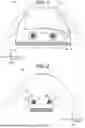
FIG. 1 This is a front view of a fan-equipped garment according to an embodiment in a state where an opening-closing means is opened.
FIG. 2 This is a back view of the fan-equipped garment according to the embodiment in a state where the opening-closing means is closed.
FIG. 3 This is a perspective view of an air-blowing device of the fan-equipped garment according to the embodiment, wherein the air-blowing device is viewed from the air sending part side.
FIG. 4 This is a perspective view of the air-blowing device of the fan-equipped garment according to the embodiment, wherein the air-blowing device is viewed from the air introducing part side.
FIG. 5 This is a perspective view of the exploded air-blowing device of the fan-equipped garment according to the embodiment.
FIG. 6 This is a cross-sectional view of the exploded air-blowing device of the fan-equipped garment according to the embodiment.
DESCRIPTION OF EMBODIMENTS
Hereinafter, an embodiment of the present invention applied to a fan-equipped garment is described, based on FIG. 1 to FIG. 6. The technical scope of the present invention is not limited to the illustrated example. The embodiment described below can be variously modified within the range of not departing from the scope of the invention.
In the following, the state where a wearer wears the fan-equipped garment 100 is set as a basic state. The forward direction from the wearer is the front; the backward direction from the wearer is the back; the upward direction from the wearer is up; the downward direction from the wearer is down; the rightward direction from the wearer is the right; and the leftward direction from the wearer is the left. The axis along the front-back direction is the X axis; the axis along the right-left direction is the Y axis; and the axis along the up-down direction is the Z axis.
In the state where the opening-closing means 11 of the garment body 1 is open as illustrated in FIG. 1, the direction in which the inner surface side of the garment body 1 (the side that faces the wearer's body when worn by the wearer) faces is the front, and the opposite direction is the back. In the description of only the air-blowing device 2, the directions of the air-blowing device 2 are described, based on the state where the air-blowing device 2 is mounted on the fan-equipped garment 100.
1 CONFIGURATION OF EMBODIMENT
As illustrated in FIG. 1, the fan-equipped garment 100 according to the embodiment includes: the garment body 1; the air-blowing devices 2 that introduce air inside the garment body 1 (into the space between the garment body 1 and the body of the wearer); a power supply device 3 that supplies voltage to the air-blowing devices 2; and a power cable 4 that connects the power supply device 3 to the air-blowing devices 2. The fan-equipped garment 100 circulates the air introduced inside the garment body 1 by the air-blowing devices 2 along the body surface of the wearer or along the surface of the underwear worn under the garment body 1 and then releases the air from air discharge parts 14 formed at the collar and sleeves of the garment body 1. Thus, the sweat drained from the body evaporates, and the body is cooled by evaporation heat at the time of evaporation.
(1) Garment Body
The garment body 1 is a garment part of the fan-equipped garment 100 except the air-blowing devices 2, the power supply device 3, and the power cable 4. As illustrated in FIG. 1 and FIG. 2, the garment body 1 is a blouson-type upper garment that covers the trunk and arms of the wearer.
The shape of the garment body 1 is not limited to this as long as the garment body 1 covers at least part of the wearer's body. For example, the garment body 1 may be a vest type that covers only the trunk of the wearer.
The surface of the garment body 1 that faces the wearer when the wearer wears the garment body 1 is referred to as the inner surface side, and the opposite surface of the garment body 1 that faces the exterior space when the wearer wears the garment body 1 is referred to as the outer surface side.
The garment body 1 includes the opening-closing means 11 on the front body, as illustrated in FIG. 1. The opening-closing means 11 includes a line fastener or the like and is the divided parts attachable to and detachable from each other. The garment body 11 includes an air leakage preventing means 12 at the hem, as illustrated in FIG. 1 and FIG. 2. The air leakage preventing means 12 includes an elastic member, such as a rubber string, disposed at the hem to surround the wearer's body. The air leakage preventing means 12 prevents air inside the garment body 1 from leaking to the outside through the hem of the garment body 1.
On the back body of the garment body 1 at positions corresponding to the left and right waist of the wearer, air-blowing device mount holes 13 are formed, as illustrated in FIG. 1 and FIG. 2. The air-blowing device mount holes 13 are round holes that connect the space inside the garment body 1 and the space outside the garment body 1 when the wear wears the fan-equipped garment 100.
The air-blowing device mount holes 13 are formed to have a diameter approximately equal to the diameter of the tubular part 2412 of the housing 241 of the case body 24 of the air-blowing device 2, which are described later. The air-blowing devices 2 are each mounted on the garment body 1 by inserting the tubular part 2412 through the air-blowing device mount hole 13, so that the outside air can be introduced to the space inside the garment body 1 via the air-blowing device mount holes 13.
The air discharge parts 14 are formed at the opening between the neck of the wearer and the edge of the collar of the garment body 1 and at the openings between the arms of the wearer and the edges of the sleeves of the garment body 1, as illustrated in FIG. 1 and FIG. 2. The air discharge parts 14 are the openings for discharging the air that has been introduced into the garment body 1 by the air-blowing devices 2 and that has circulated along the wearer's body or the underwear.
On the inner surface side of the garment body 1, a power supply device holder 15 and a power cable holder 16 are provided, as illustrated in FIG. 1. The power supply device holder 15 is pocket-shaped to house the power supply device 3 for holding the power supply device 3 at the position where the power supply device 3 is connectable to the air-blowing devices 2 via the power cable 4. The power cable holder 16 is ring-shaped and has an opening through which the power cable 4 can be inserted for holding the power cable 4 on the inner surface side of the garment body 1.
(2) Air-Blowing Device
The air-blowing devices 2 are devices for introducing air to the space between the garment body 1 and the wearer's body through the air-blowing device mount holes 13. As illustrated in FIG. 1 and FIG. 2, each air-blowing device 2 is attached to the air-blowing device mount hole 13 of the garment body 1 such that the air introducing part 2421 of the case body 24, which is described later, is at the outer surface side of the garment body 1 and the air sending part 2411 is at the inner surface side of the garment body 1.
The air-blowing devices 2 are supplied with necessary voltage by the power supply device 3 via the power cable 4.
As illustrated in FIG. 3 to FIG. 6, each air-blowing device 2 includes: a blade 21; a motor 22 for rotating the blade 21; a connection cord 23 to be connected to the power cable 4 for supplying voltage to the motor 22 from the power supply device 3; a casing body 24 that houses the blade 21 and the motor 22; and a mount ring 25 that is a ring-shaped member for fastening the case body 24 to the garment body 1.
a. Blade
The blade 21 is a means for generating an air flow from the air introducing part 2421 side to the air sending part 2411 side of the case body 24, which are described later, by being rotated by the motor 22.
FIG. 3 to FIG. 6 illustrate a so-called propeller fan having a propeller shape as the blade 21. However, the shape of the blade 21 is not specifically limited as long as the blade 21 can generate an air flow from the air introducing part 2421 side to the air sending part 2411 side of the case body 24, which are described later.
b. Motor
The motor 22 is a means for rotating the blade 21 and provided at the central part of the blade 21. The motor 22 is supplied with voltage by the power supply device 3 and rotates the blade 21 on the rotation axis that passes through the center of the air introducing part 2421 and the center of the air sending part 2411 of the case 24 (the axis parallel to the X axis in FIG. 1 and FIG. 2). As the motor 22, a brushless motor that does not have therein electrodes called “brushes” is used.
As illustrated in FIG. 5 and FIG. 6, the motor 22 includes an electrical part 221, a magnet 222, and bearings 223.
The electrical part 221 is a part of the motor 22, such as a coil, through which current flows when voltage is supplied by the power supply device 3.
The magnet 222 is a ring-shaped magnet. As illustrated in FIG. 5 and FIG. 6, the magnet 222 is arranged to cover the electrical part 221.
The bearings 223 are members for supporting the rotation shaft of the electrical part 221. The bearings 223 are provided at both the front and back sides of the electrical part 221.
In the motor 22, the entire electrical part 221 is sealed by resin to have the waterproof property.
Having the waterproof property refers to a case where water does not enter inside when water is poured in washing, or more specifically, a case where the IP68 is met.
The resin for sealing the motor 22 is not specifically limited as long as the above-described waterproof property can be obtained. The resin may be, for example, ABS resin.
c. Connection Cord
The connection cord 23 is a cord-shaped member for holding a power jack 231 at a position separate from the blade 21, the motor 22, and the case body 24. One end of the connection cord 23 is connected to the electrical part 221 of the motor 22, and the other end is provided with the power jack 231. The power jack 231 is a connection part to be connected to a power plug 41 of the power supply device 4 for supplying voltage from the power supply device 3 to the motor 22.
The power jack 231 may be any type that is connectable to the power plug 41 of the power cable 4. The power jack 231 may be a general DC jack, for example.
The connection cord 23 except the power jack 231 has the same level of waterproof property as the electrical part 221 of the motor 22. The connection part at which the connection cord 23 is connected to the electrical part 221 of the motor 22 also has the same level of waterproof property as the electrical part 221 of the motor 22 by being sealed by resin, for example.
A terminal having a waterproof property may be used as the power jack 231 so that the power jack 231 also has the same level of waterproof property as the electrical part 221 of the motor 22. Since the air-blowing device 2 can be washed while keeping only the power jack 231 away from water as described later, the power jack 231 may not have the waterproof property.
d. Case Body
The case body 24 is a case that houses the blade 21 and the motor 22. As illustrated in FIG. 3 to FIG. 6, the case body 24 includes a housing 241 that houses the blade 21 and the motor 22; a finger guard 242 for covering an opening 2413 formed at one end of the housing 241; and a cover plate 243 attached to the end of the housing 241 opposite the finger guard 242.
(a) Housing
The housing 241 is the main body of the case body 24 that houses the blade 21 and the motor 22. As illustrated in FIG. 5 and FIG. 6, the housing 241 includes: the air sending part 2411 that is a mesh-patterned part through which air is sent out when the blade 21 is rotated; the tubular part 2412 that is sequentially formed from the air sending part 2411; the opening 2413 that is a round opening formed at a surface opposite the air sending part 2411; and a flange 2414 that protrudes from the opening 2413-side end of the tubular part 2412 in a direction substantially perpendicular to the lateral surface of the tubular part 2412.
The tubular part 2412 has a cylindrical shape. The external shape of the cross section of the tubular part 2412 is a substantially perfect circle when the tubular part 2412 is cut along a plane (Y-Z plane) perpendicular to the rotation axis (X axis) of the blade 21. The outer diameter of the tubular part 2412 is approximately equal to the diameter of the air-blowing device mount hole 13, At two opposite positions on the outer surface of the tubular part 2412, case body-side fitting parts 24121 are formed. The case body-side fitting parts 24121 are the projected and/or recessed parts that fit to mount ring-side fitting parts 251 that are the projected and/or recessed parts formed on the inner surface side of the mount ring 25, which is described later, so that the mount ring 25 can be fixed to the outer surface side of the tubular part 2412 as described later.
(b) Finger Guard
The finger guard 242 is a member attached to cover the opening 2413 of the housing 241. As illustrated in FIG. 4 to FIG. 6, the finger guard 242 is round-shaped, and the mesh-patterned air introducing part 2421 is formed over the entire finger guard 242 except the peripheral part. When the blade 21 is rotated, air is introduced through the air introducing part 2421.
(c) Cover Plate
The cover plate 243 is a round plate member. As illustrated in FIG. 3, FIG. 5, and FIG. 6, the cover plate 243 is attached to cover the central part of the housing 241.
e. Mount Ring
The mount ring 25 is an integrally formed ring-shaped member made of an elastic material, such as plastic. As illustrated in FIG. 3 and FIG. 4, the mount ring 25 is attached to the tubular part 2412 of the housing 241 of the case body 24 such that the mount ring 25 covers the outer surface of the tubular part 2412. One end of the mount ring 25 and the flange 2414 of the housing 241 of the case 24 sandwich the part around the air-blowing device mount hole 13 of the garment body 1, so that the air-blowing device 2 is attached to the garment body 1, as illustrated in FIG. 1 and FIG. 2.
The mount ring 25 has an oval ring shape when viewed in the rotation axis direction of the blade 21 (X-axis direction). The internal circumference of the mount ring 25 is longer than the outer circumference of the tubular part 2412 of the housing 241 of the case body 24. The shorter diameter of the internal circumference of the mount ring 25 is shorter than or equal to the diameter of the outer circumference of the tubular part 2412 of the housing 241 of the case body 24. In this case, the longer diameter of the internal circumference of the mount ring 25 is greater than the diameter of the outer circumference of the tubular part 2412 of the housing 241 of the case body 24.
At two opposite positions in the shorter diameter direction on the inner surface of the mount ring 25, the mount ring-side fitting parts 251 are formed. The mount ring-side fitting parts 251 are the projected and/or recessed parts that fit to the case body-side fitting parts 24121, which are the projected and/or recessed parts formed on the outer surface side of the tubular part 2412 of the housing 241 of the case body 24.
The mount ring 25 is elastic, as mentioned above. When the mount ring 25 is pressed in the longer-diameter direction from the outer surface side, the shorter-diameter direction of the mount ring 25 projects outward, so that the mount ring 25 can be deformed into the shape of a substantially perfect circle. When the pressing force in the longer-diameter direction from the outer surface side is released, the mount ring 25 returns to its original oval shape.
By the use of this property, the mount ring 25 can be attached to the tubular part 2412 of the housing 241 of the case body 24 as illustrated in FIG. 3 and FIG. 4 by: pressing the outer surface side of the oval-shaped mount ring 25 in the longer-diameter direction to bend and deform the mount ring 25 into the shape of a substantially perfect circle; putting the mount ring 25 to the tubular part 2412 such that the positions of the mount ring-side fitting parts 251 of the mount ring 25 correspond to the positions of the case body-side fitting parts 24121 of the tubular part 2412; and releasing the pressing on the mount ring 25.
Herein, one end of the mount ring 25 and the flange 2414 of the housing 241 of the case 24 sandwich the part around the air-blowing device mount hole 13 of the garment body 1, so that the air-blowing device 2 can be mounted on the garment body 1.
(3) Power Supply Device
The power supply device 3 is a member for supplying electrical power to the air-blowing devices 2. The power supply device 3 houses an assembled lithium-ion battery provided with a safety protection circuit and is connected to the air-blowing devices 2 via the power cable 4 as illustrated in FIG. 1, for example. The power supply device 3 also includes a switch for switching on/off of the electrical power supplied to the air-blowing devices 2.
The detailed configuration of the power supply device 3 may be determined as desired, as long as the power supply device 3 can supply electrical power to the air-blowing devices 2.
(4) Power Cable
The power cable 4 is a cable that connects the power supply device 3 to the air-blowing devices 2, as illustrated in FIG. 1. Via the power cable 4, electrical power necessary for operating the air-blowing devices 2 is supplied to the air-blowing devices 2 from the power supply device 3.
As illustrated in FIG. 1, one end of the power cable 4 is split into two branches, and each of the two branches has the power plug 41. The power plugs 41 are inserted to the power jacks 231 of the connection cords 23 of the respective air-blowing devices 2. Thus, the power cable 4 can be detachably connected to the air-blowing devices 2.
The detailed configuration of the power plugs 41 is not specifically limited as long as the power plugs 41 can be inserted to the power jacks 231 of the connection cords 23 of the air-blowing devices 2, can detachably connect the power cable 4 to the air-blowing devices 2, and can supply necessary electrical power for operating the air-blowing devices 2.
2. ADVANTAGEOUS EFFECTS OF EMBODIMENT
According to the fan-equipped garment 100 in the present embodiment, the air-blowing devices 2 each include: the blade 21 that generates an air flow; the motor 22 that rotates the blade 21; and the case body 24 that houses the blade 21 and the motor 22. The electrical part 221 included in the motor 22 has a waterproof property.
Thus, the motor 22 is less likely to break down even when water is poured on the air-blowing device 2. The air-blowing devices 2 can therefore be easily washed with water.
Further, the electrical part 221 of the motor 22 of the air-blowing device 2 is sealed by resin. Thus, the waterproof property of the motor 22 can be further enhanced.
Further, the air-blowing device 2 includes the connection cord 23 connected to the electrical part 221 of the motor 22. An end of the connection cord 23 opposite the end connected to the electrical part 221 is provided with the power jack 231 for supplying voltage to the electrical part 221 from the power supply device 3. In addition to the electrical part 221, at least part of the connection cord 23 except the power jack 231 has the waterproof property. Since the position of the power jack 231 can be separated from the blade 21 or the case body 24 of the air-blowing device 2, the air-blowing device 2 can be easily washed while keeping only the power jack 231 away from water.
3. MODIFICATION EXAMPLE
Next, a modification example of the fan-equipped garment 100 according to this embodiment is described.
(1) Changes to an Article Equipped With the Air-Blowing Device
In the above description of the configuration and effects, the fan-equipped garment 100 is described as an example of the article equipped with the air-blowing device 2. The article equipped with the air-blowing device 2 is not limited to the fan-equipped garment 100 and may be any such article that allows introduction of air into the main body by the air-blowing device 2.
For example, the air-blowing device 2 may be provided to: a seat cushion and bedding that have the function of introducing air between two sheets to cool the body part in contact with the sheets; a helmet that has the function of circulating air inside the helmet to cool the wearer's head; and a backpack that has the function of introducing air into the backpack to cool the wearer's back. Any of the above articles corresponds to an article equipped with the air-blowing device of the present invention.
(2) Adding Terminal Cover
A cover having a waterproof property may be provided to cover the connection part between the power jack 231 provided to the connection cord 23 of the air-blowing device 2 and the power plug 41 of the power cable 4 in the state where the power jack 231 and the power plug 41 are connected. With the cover covering the connection part between the power jack 231 and the power plug 41, the connection part is provided with the same level of waterproof property as the electrical part 221 of the motor 22. Accordingly, water can be poured over the entire connection cord 23 in the state where the power cable 4 is attached to the air-blowing device 2. Such a configuration makes it easier to wash the air-blowing device 2 with water in the state where the power cable 4 is attached to the air-blowing device 2.
INDUSTRIAL APPLICABILITY
The present invention is suitably applicable to a production field of an air-blowing device and an article equipped with the air-blowing device.
REFERENCE SIGNS LIST
-
- 100 Fan-equipped garment (article equipped with air-blowing device)
- 1 Garment body (main body)
- 2 Air-blowing device
- 21 Blade
- 22 Motor
- 221 Electrical part
- 23 Connection cord
- 231 Power jack (power supply part)
- 24 Case body
- 25 Mount ring
- 3 Power supply device
- 4 Power cable
- 41 Power plug
Claims
1. An air-blowing device comprising:
a blade that generates an air flow;
a motor that rotates the blade; and
a case body that houses the blade and the motor,
wherein the motor includes an electrical part that has a waterproof property.
2. The air-blowing device according to claim 1, wherein the electrical part is sealed by resin.
3. The air-blowing device according to claim 1, further comprising a connection cord connected to the electrical part, wherein:
the electrical connection cord includes a power supply part for supplying voltage to the electrical part from a power supply device, the power supply part being provided at an end of the connection cord opposite an end connected to the electrical part, and
in addition to the electrical part, at least part of the connection cord except the power supply part has a waterproof property.
4. An article equipped with an air-blowing device, the article comprising:
the air-blowing device according to claim 1;
a main body into which air is introduced by the air-blowing device; and
a power supply device that supplies voltage to the air-blowing device.
5. The article equipped with the air-blowing device according to claim 4, further comprising a power cable that connects the power supply device to the air-blowing device, wherein a connection part at which the power cable is connected to the air-blowing device is covered by a cover that has a waterproof property.
Images & Drawings included:


Sources:
- United States Patent and Trademark Office - verify current appl. status at the USPTO↗
Recent applications in this class:
- » 20260053210 2026-02-26
COOLING VEST MODULE - » 20250248463 2025-08-07
COOLING DEVICE FOR CLOTHES - » 20250228308 2025-07-17
PERSONAL COOLING GARMENT AND COOLING DEVICE - » 20250127246 2025-04-24
IOT-BASED COLD VEST - » 20250107580 2025-04-03
COOLING DEVICE FOR CLOTHES - » 20250098799 2025-03-27
ICT TECHNOLOGY-BASED COOLING CLOTHING - » 20240381953 2024-11-21
Air Cooling Device for Protective Clothing and System Thereof - » 20240315363 2024-09-26
Flame Resistant Utility Suit - » 20240156185 2024-05-16
WEARABLE THERMAL CONDITIONING SYSTEMS - » 20240138497 2024-05-02
INTELLIGENT CONTROL SYSTEM AND METHOD FOR COOLING DEVICE FOR MANNEQUIN COSTUMES