BRISTLE TUFT, BRUSH ROLLER WITH BRISTLE TUFT, AND DISASSEMBLY METHOD OF BRUSH ROLLER
US20260101993A1
2026-04-16
19/359,806
2025-10-16
Smart Summary: A bristle tuft is made up of many bristles grouped together. This tuft is used in a brush roller designed for creating printed flooring that looks like wood. Each bristle has a root that attaches to the roller, a head that sticks out, and a spacing section that keeps the bristles apart. The spacing helps the bristles work better by preventing them from clumping together. There is also a method for taking apart the brush roller when needed. 🚀 TL;DR
Abstract:
A bristle tuft, a brush roller with the bristle tuft, and a disassembly method of the brush roller, used in flooring production, particularly in the manufacture of printed flooring with three-dimensional wood grain textures on the surface. The bristle tuft comprises a plurality of bristles gathered into a tuft, wherein at least one bristle includes: a general root segment for mounting on a roller body, a general head segment extending in a direction perpendicular to the rotation axis of the roller body, and a spacing segment disposed between the general root segment and the general head segment, used to space apart at least one adjacent bristle to form a separated state except for the general root segment, the spacing segment having a spacing structure.
Inventors:
- Guocui Yang 3 🇨🇳 Hangzhou City, China
- Zhongshan Lei 3 🇨🇳 Hangzhou City, China
- Mengde Deng 3 🇨🇳 Hangzhou City, China
- Donghui Huang 3 🇨🇳 Hangzhou City, China
- Fangbing Ao 3 🇨🇳 Hangzhou City, China
- Feng Huang 3 🇨🇳 Hangzhou City, China
Applicant:
Interested in similar patents?
Get notified when new applications in this technology area are published.
Classification:
A46D1/0253 » CPC main
Bristles; Selection of materials for bristles; Bristles details Bristles having a shape which is not a straight line, e.g. curved, "S", hook, loop
A46B9/026 » CPC further
Arrangements of the bristles in the brush body; Position or arrangement of bristles in relation to surface of the brush body, e.g. inclined, in rows, in groups where the surface of the brush body or carrier is not in one plane, e.g. not flat
A46D1/0207 » CPC further
Bristles; Selection of materials for bristles; Bristles details Bristles characterised by the choice of material, e.g. metal
A46D1/023 » CPC further
Bristles; Selection of materials for bristles; Bristles details Bristles with at least a core and at least a partial sheath
A46B2200/3073 » CPC further
Brushes characterized by their functions, uses or applications; Brushes for cleaning or polishing Brush for cleaning specific unusual places not otherwise covered, e.g. gutters, golf clubs, tops of tin cans, corners
E04F15/105 » CPC further
Flooring; Flooring or floor layers composed of a number of similar elements of other materials, e.g. fibrous or chipped materials, organic plastics, magnesite , hardboard of organic plastics with or without reinforcements or filling materials
A46D1/00 IPC
Bristles; Selection of materials for bristles
A46B9/02 IPC
Arrangements of the bristles in the brush body Position or arrangement of bristles in relation to surface of the brush body, e.g. inclined, in rows, in groups
E04F15/10 IPC
Flooring; Flooring or floor layers composed of a number of similar elements of other materials, e.g. fibrous or chipped materials, organic plastics, magnesite , hardboard
Description
TECHNICAL FIELD
The present disclosure generally relates to the process of forming three-dimensional textures on the surface of a board, particularly to forming three-dimensional wood grain textures on the surface of a board.
The present invention pertains to the field of flooring, particularly to the field of printed flooring with three-dimensional wood grain textures on the surface, and specifically relates to a bristle tuft, a brush roller with the bristle tuft, and a disassembly method of the brush roller.
BACKGROUND ART
Flooring with wood grain is widely used in the field of interior decoration due to its higher aesthetic appeal and softer tones. However, solid wood flooring is expensive, limiting its market reach. Based on this, flooring with imitation wood grain three-dimensional textures is widely manufactured and sold, such as wood-plastic flooring with three-dimensional wood grain on the surface. In a known production method for three-dimensional wood grain wood-plastic flooring, the steps are as follows:
-
- S1. Print a wood grain decorative base pattern onto a wood-plastic panel in a first printing step to form a patterned board;
- S2. Uniformly coat a curable substance on the patterned board; this step may be performed multiple times to form a first board to be cured;
- S3. Transfer the board to be cured to a digital printing workstation, where the digital printing, based on known wood grain coordinate information from the first printing step, prints a polymerization inhibitor onto the board to be cured, aligning the polymerization inhibitor with the wood grain to form a second board to be cured;
- S4. Subject the second board to be cured to a curing process, such as a photocuring process;
- S5. Simultaneously remove the polymerization inhibitor and part of the incompletely cured curable substance to form a three-dimensional wood grain board.
The polymerization inhibitor is generally a non-curable substance. The methods by which the polymerization inhibitor achieves the formation of textured patterns on the surface of the curable substance mainly include the following:
-
- a. The polymerization inhibitor is dropped onto the curable substance, occupying part of the space originally occupied by the curable substance. Since the polymerization inhibitor itself does not cure, it can be removed after the curing process, leaving indentations at the positions originally occupied by the curable substance;
- b. The polymerization inhibitor is dropped onto the curable substance, forming a mixture with a portion of the underlying curable substance. This mixture cures at a slower rate than the original curable substance and remains incompletely cured during the curing process, allowing it to be removed after the curing process and leaving indentations at its original positions;
- c. The polymerization inhibitor is dropped onto the curable substance, hindering the curing process of the underlying curable substance, for example, by blocking or impeding light from contacting the curable substance during a photocuring process. The blocked portion of the curable substance cures more slowly and remains incompletely cured during the curing process, allowing it to be removed after the curing process and leaving indentations at its original positions;
In methods b and c, the mixture formed by the polymerization inhibitor and a portion of the underlying curable substance, or the curable substance blocked by the polymerization inhibitor, is referred to as a slow-curing substance. The slow-curing substance has a slower curing rate than the curable substance, so that when the curable substance is fully cured, the slow-curing substance remains incompletely cured and can be physically removed. Various methods exist for removing the slow-curing substance, such as using high-speed fluid flushing. However, the surface structure edges obtained by such methods are smooth, significantly differing from naturally formed wood grain structures. In another method, a roughened texture is applied to at least a portion of the surface structure using one or more (rotating) brush rollers. During the removal of the slow-curing substance, this results in a surface structure with a contour more closely resembling natural wood grain in appearance and feel, typically also featuring sharp edges (indistinguishable, discontinuous edges) rather than conventional smooth, rounded edges (typically achieved through high-speed fluid flushing), improving the visual appearance and/or tactile (touch) characteristics of the surface structure. Such brush rollers are typically used in various board surface treatment processes, such as the wire roller described in CN112264894A and the wire drawing roller described in CN112589639B. Their typical feature is that the bristles are radially arranged on the surface of the roller, and the distance between the roller axis and the board surface is slightly less than the distance from the bristle head segment to the roller axis, allowing the bristle head segment to partially penetrate the board and remove part of the material from the board surface. This material may be part of the board itself or an embossed substance formed after pretreatment of the board (typically a wood grain structure formed by the slow-curing substance).
In particular, the slow-curing substance has a viscous property. When existing brush rollers used for processing surfaces such as wood, metal, or ceramics are used to remove the slow-curing substance, the slow-curing substance cannot be quickly removed like material debris and often remains on the bristle head segment, forming residues. These residues cannot be removed by the rotation of the brush roller or a suction device, causing the bristle head segment covered by the residues to be concealed, limiting its functionality in subsequent use.
In the prior art, the bristles applied to brush rollers are mostly of a linear configuration, which leads to the bristles being more likely to be arranged in clusters. After adhering to the slow-curing substance, these clustered bristles inevitably stick together, losing their function of wire drawing to form three-dimensional wood grain in the production process of wood-plastic flooring. Restoring functionality requires cleaning the bristles, which necessitates disassembling the entire brush roller from the production line, leading to reduced production efficiency.
In addition, KR1020090086739A discloses a linear bristle structure arranged on a roller body, using mounting grooves on the roller surface to clamp the root segments of the bristles inward, allowing the head segments to spread out. It can be foreseen that when applied to the production process of three-dimensional wood grain wood-plastic flooring, this reduces the tendency for adhesion of the slow-curing substance. However, in this configuration, the bristles are much more densely gathered in the middle than at the sides, and this gathering is even denser than when directly arranged on the roller body. When directly applied to the production method of three-dimensional wood grain wood-plastic flooring, the slow-curing substance more tightly binds the middle bristle head segments together, causing these local bristles to fail directly during production. This results in the need to disassemble and clean the entire brush roller, even if other parts of the bristles still retain wire-drawing capability during production.
SUMMARY OF THE INVENTION
One of the objectives of the present invention is to provide a bristle tuft with the characteristic of reducing the risk of the bristle head segments being stuck together by residues of the slow-curing substance.
The second objective of the present invention is to provide a brush roller with the characteristic of being quickly disassembled from a production line, thereby reducing production line downtime and improving production efficiency.
The third objective of the present invention is to provide a brush roller equipped with the aforementioned bristle tuft.
The fourth objective of the present invention is to provide a disassembly method for the aforementioned brush roller.
The fifth objective of the present invention is to provide a method for preparing a surface structure using the aforementioned brush roller.
The technical solution adopted by the present invention to solve the above problems is: a bristle tuft for removing uncured resin from the surface of a substrate, comprising:
A plurality of bristles gathered into a tuft, wherein at least one bristle comprises:
A general root segment for mounting on a roller body, and a general head segment extending in a direction perpendicular to the rotation axis of the roller body, and a spacing segment disposed between the general root segment and the general head segment and used to space apart at least one adjacent bristle to form a separated state except for the general root segment, the spacing segment having a spacing structure.
In the present application, the general root segment, the general head segment, and the spacing segment constitute the bristle, wherein:
General root segment: Located on the side of the bristle facing the roller body and having an end for fixing to the roller body.
General head segment: Located on the side of the bristle away from the roller body and having an end extending outward to perform the functions of wire drawing and impurity removal of the bristle.
Spacing segment: Located between the general root segment and the general head segment.
The presence of the spacing segment enables the bristles to be spaced apart, which drives the bristles to have the ability to resist adhesion of the slow-curing substance. Even when the bristles are mounted on the roller body surface through grooves, the presence of the spacing segment significantly reduces the phenomenon of midsection gathering.
Wherein, the spacing structure can be formed by structural transformation of the bristle body, resulting in lower manufacturing costs.
A further preferred technical solution is that: the material of the bristles is metal.
Metal has better shape-changing properties while having sufficient hardness to support the shaping process of the surface structure. On the other hand, metal can resist wear effects from cleaning devices such as scrapers during subsequent cleaning processes, allowing the bristles to maintain their original morphology and functionality after multiple cleanings, thereby maximizing their service life.
A further preferred technical solution is that: the spacing structure is formed by bending part or all of the bristle body of the spacing segment.
The bending structure is produced by deformation of the bristle body through mold pressing, extrusion technology, or winding technology. The bending structure portion can be similar to the shape of instant noodles or a spring. In short, the bending structure provides a radially outward expansion structure in the middle of the bristle, and due to the material of the bristle body, this expansion structure retains a certain elasticity.
A further preferred technical solution is that: the bending is a spiral bending, and the spiral coils are sequentially arranged along the extension direction of the bristle.
A further preferred technical solution is that: the spacing structure of the spacing segment is an enlarged portion where the bristle diameter in the spacing segment is significantly larger than the bristle diameter of the general root segment.
Wherein, “significantly” means that, from the perspective of an ordinary person, the enlarged portion is thicker than the general root segment. Functionally, the enlarged portion enables at least one bristle to be spaced apart from the present bristle to form a separated state.
A further preferred technical solution is that: the spacing structure is a sleeve fixed on the spacing segment of the bristle, the sleeve being sleeved on the outside of the bristle.
A further preferred technical solution is that: the maximum dimension of the external contour one of the root segment and the head segment is 2 mm. Preferably, the external contour one is 0.5-1 mm.
Wherein, the dimension of the external contour one refers to the diameter of the smallest circle that can encompass the cross-sectional surface of the general root segment or the general head segment.
The larger the dimension of the external contour one of the bristle, the higher its rigidity, but the poorer its deformation capability and the lower the fineness of wire drawing. Conversely, bristles with smaller diameters have higher wire-drawing fineness and deformation capability but lower rigidity and reduced ability to remove the slow-curing substance from the surface structure. Therefore, the dimension of the external contour one of the bristle should be determined within a reasonable range.
A further preferred technical solution is that: the maximum dimension of the external contour two of the spacing segment is 5 mm.
Wherein, the dimension of the external contour two refers to the diameter of the smallest circle that can encompass the cross-sectional surface of the spacing segment.
A further preferred technical solution is that: assuming the total length of the bristle is X and the straight-line distance from the root segment endpoint to the head segment endpoint is Y, then X:Y=1:1-0.8.
When the bristle body is not deformed, X:Y should be 1:1. In this case, the spacing segment is not formed by the deformation of the bristle body itself, such as a rubber sleeve or spring sleeved on the bristle body.
For a bending structure formed by the deformation of the bristle body itself, the X value remains unchanged while the Y value decreases. The smaller the Y value, the greater the degree of bending of the bending structure, and the larger the spacing distance between bristles. When the spacing distance between bristles reaches a certain value, it affects the overall density of the bristles. The density of the bristles is closely related to their ability to produce a wire-drawing effect. When the bristle arrangement density is insufficient to remove the slow-curing substance in time, it is considered substandard. Therefore, the ratio of X to Y should be controlled within a reasonable range.
A further preferred technical solution is that: the spacing structure is a coating covering the spacing segment of the bristle.
The coating is a substance, such as a polymer, applied to the bristle body to isolate the bristles.
A brush roller, comprising:
-
- A roller body having a cylindrical structure and a rotation axis arranged along the axis of the cylinder;
- Bristles disposed on the surface of the roller body;
- A roller sleeve for rotatably mounting the rotation axis and provided with an outer fixing member;
- A suspension component disposed above a conveyor belt in a production line, the suspension component being provided with a suspension groove for slidably mounting the roller sleeve along the extension direction of the rotation axis, and the suspension groove being configured with an inner fixing member for fixing the outer fixing member.
After the bristles are treated as described above, the coverage of the slow-curing substance on the general head segment of the bristles is reduced. However, in actual production processes, after prolonged operation, the general head segment of the bristles will still adhere to the slow-curing substance, causing the brush roller to lose its wire-drawing function. To enable the brush roller to function again, it is necessary to disassemble the brush roller from the production line and promptly clean the slow-curing substance adhered to the bristle head segment. However, during the disassembly process, the production line must be stopped, and the disassembly time directly affects the production efficiency of the production line.
The core technical concept of quick disassembly of the brush roller lies in reducing the proportion of the total weight of the roller body borne by the fixing components directly fixing the roller body in the suspension component, such as the inner fixing member, while increasing the proportion of the total weight of the roller body borne by the fixing components not directly fixing the roller body, such as the suspension groove or other clamping structures. This is because it is understandable that the time required to disassemble the roller body from non-directly fixed components is much less than the time required to disassemble it from directly fixed components.
Based on this, in the present invention, the component used to fix and bear the majority of the weight of the roller body is the suspension groove, while the direct fixing system formed by the inner and outer fixing members is provided to assist the suspension groove. After the roller body is slidably mounted onto the suspension groove through the roller sleeve, the roller sleeve is fixed to the suspension groove by the inner and outer fixing members. During subsequent disassembly, only a minimal number of inner and outer fixing members need to be removed, allowing the roller sleeve to be easily disassembled from the suspension groove by reverse sliding.
A further preferred technical solution is that: the slotting direction of the suspension groove is perpendicular or substantially perpendicular to the running direction of the conveyor belt.
Wherein, the “slotting direction” refers to the extension direction of the longer side of the suspension groove, which is the same as the extension direction of the rotation axis of the roller body. “Substantially perpendicular” means that, under existing measurement methods, the slotting direction of the suspension groove is completely perpendicular to the conveyor belt, or it is considered perpendicular based on the observation of a person skilled in the art, but not completely perpendicular in a mathematical sense.
When disassembling the roller body, consideration must be given to whether the roller body can be quickly transferred after disassembly. When the slotting direction of the suspension groove is substantially perpendicular to the conveyor belt, the roller body can be completely removed from above the conveyor belt after sliding out of the suspension groove, facilitating timely transfer by a transfer device such as a cart or forklift placed below.
A further preferred technical solution is that: the suspension groove comprises a main space and side spaces extending from the main space to both sides; the inner fixing member is disposed inside the suspension component and configured in the side spaces.
A further preferred technical solution is that: the suspension component comprises a plate body for forming the suspension groove, the plate body comprising an upper plate, side plates disposed at both side ends of the upper plate, and a lower plate disposed at the lower end of the side plates; the upper plate comprises upper plate side regions vertically opposite to the lower plate, and an upper plate middle region located between the two upper plate side regions; the upper plate side regions, side plates, and lower plate define the side spaces, and the upper plate middle region defines the main space.
A further preferred technical solution is that: the inner fixing member is disposed on the upper end surface of the lower plate.
A further preferred technical solution is that: the roller sleeve comprises a roller mounting member for rotatably mounting the rotation axis, a suspension plate for mounting the roller mounting member, and hanging lugs disposed on both sides of the suspension plate; the outer fixing member is disposed on the lower end surface of the hanging lugs.
A further preferred technical solution is that: the outer fixing member and the hanging lugs form a mounting contour configured to match the shape of the inner fixing member.
A further preferred technical solution is that: the outer fixing member and the inner fixing member are respectively configured with fixing holes of the same specification, fixed simultaneously by a fixing bolt.
A further preferred technical solution is that: the axis of the fixing holes is parallel to the axis of the roller body.
A further preferred technical solution is that: the fixing holes are provided with internal fixing threads, and the fixing bolt is provided with external fixing threads screwed with the internal fixing threads.
A further preferred technical solution is that: the outer fixing member and the inner fixing member have the same or substantially the same height.
After the roller sleeve is mounted on the suspension groove, the outer fixing member contacts the lower plate of the suspension groove. When the inner fixing member and the outer fixing member have substantially the same height, the inner fixing member can also contact the roller sleeve simultaneously, achieving a block-like clamping effect through the inner and outer fixing members to fully support the roller sleeve. Additionally, when the outer fixing member slides on the lower plate, the roller sleeve can also slide above the inner fixing member, ensuring that the horizontal height of the roller body does not change during the sliding installation process, making the sliding process smoother.
“Substantially the same” means that, under existing measurement methods, the inner and outer fixing members are observed to be completely identical, or considered identical based on the observation of a person skilled in the art, but not completely identical in a mathematical sense.
A further preferred technical solution is that: assuming the end of the suspension plate near the outer fixing member is the proximal end; the roller sleeve further comprises an end handle disposed at the proximal end of the suspension plate.
The end handle can be used to assist in pulling the roller body out of the suspension groove. Since the end handle is oriented substantially perpendicular to the running direction of the conveyor belt, workers can stand on the side of the conveyor belt to pull the roller body out of the suspension groove.
A further preferred technical solution is that: the roller sleeve further comprises side handles disposed on the outer side of the hanging lugs.
The side handles can assist the end handle in pulling the roller body out of the suspension groove. For example, it is impractical to support a long roller body solely through one end when it is about to be detached from the suspension groove. Additionally, when the roller body is partially pulled out of the suspension groove for subsequent transfer, there is a moment when the side handles are released, but the transfer device has not yet fully supported the roller body, which may cause the roller body to slide uncontrollably.
A further preferred technical solution is that: the side handles are groove handles formed by inward recesses on the outer side of the hanging lugs.
After the roller sleeve is mounted into the suspension groove, the side handles are also located within the suspension groove. In some cases, the side of the roller sleeve fits closely with the suspension groove, meaning that the side and bottom surfaces of the roller sleeve participate in the sliding process within the suspension groove. When the side handles are designed to be recessed inward along the side of the roller sleeve, such as groove handles, the side of the roller sleeve can fit closely with the inner side of the suspension groove without restriction during the sliding process.
A further preferred technical solution is that: the roller sleeve further comprises an auxiliary fixing member disposed at the distal end of the suspension plate; the suspension component further comprises an auxiliary receiving member disposed on the plate body and used for mounting the auxiliary fixing member.
The auxiliary fixing member and the auxiliary receiving member are fixed by a plug-in method, which serves to assist the inner and outer fixing members. This plug-in fixing method is fast for both installation and disassembly without requiring bolts. Its primary role is to maintain the horizontal state of the other end of the roller sleeve, preventing movement due to the rotation of the roller body.
A further preferred technical solution is that: the auxiliary fixing member is located on the opposite side of the outer fixing member.
“Opposite side” refers to being located on different opposite sides, for example, if the outer fixing member is disposed on the left end of the roller sleeve, the auxiliary fixing member is disposed on the right end of the roller sleeve.
A further preferred technical solution is that: the distal end of the roller body is further provided with a power member; the power member provides rotational power to the roller body through a transmission member connected to a power device.
A further preferred technical solution is that: the transmission member is a transmission belt.
The power member is a component that provides power to the roller body, such as a wheel capable of mounting a transmission belt. A rotor motor is provided at the other end of the transmission belt to drive the roller body to rotate. During disassembly, it is only necessary to remove the transmission belt from the power member.
The outer fixing member is oriented substantially perpendicular to the running direction of the conveyor belt.
The orientation of the outer fixing member is defined as the orientation of the operable end of the outer fixing member, such as the extension direction of the rod body of a bolt structure or the extension direction of the hole body of an internal threaded hole. This design allows workers to install or disassemble the inner and outer fixing members from the side of the conveyor belt, minimizing interference from the conveyor belt structure during operation, and even allowing disassembly/installation work to be performed without stopping the conveyor belt.
A further preferred technical solution is that: the width of the guide groove body is less than 20 mm.
A further preferred technical solution is that: there is a bristle space between adjacent guide groove bodies, the width of the bristle space being 1-20 mm.
A further preferred technical solution is that: the groove wall thickness of the guide groove body is 1-10 mm.
A disassembly method for a brush roller, comprising the following steps:
-
- S01. Remove the locking device between the inner fixing member and the outer fixing member;
- S02. Pull the roller sleeve out of the suspension groove.
Wherein, step S02 comprises:
-
- S02-1. Partially pull the roller sleeve out of the suspension groove and use a transfer device to support the portion of the roller sleeve protruding from the suspension groove;
- S02-2. Continue pulling the roller sleeve until the entire roller sleeve is detached from the suspension groove and completely enters the transfer device.
A further preferred technical solution is that: the transfer device is provided with a support device for supporting the roller sleeve, the support device having substantially the same height as the suspension component.
A method for preparing a surface structure, the surface structure being disposed on the surface of a substrate, comprising the following steps:
-
- S11. Install the brush roller above a conveyor belt, the running direction of the conveyor belt being perpendicular to the rotation axis of the brush roller, and the distance between the brush roller and the conveyor belt being greater than the thickness of the substrate;
- S12. Cause at least a portion of the surface of the substrate to be covered with at least one layer of base agent;
- S13. Cause at least a portion of the surface of at least one layer of base agent to be applied with a polymerization inhibitor, so that at least a portion of the base agent mixed with the polymerization inhibitor or at least a portion of the base agent covered by the polymerization inhibitor forms a slow-curing substance;
- S14. Cause the base agent and the slow-curing substance to undergo polymerization;
- S15. Transport the substrate through the conveyor belt to below the brush roller, and use the bristles to remove the slow-curing substance.
Wherein, the polymerization inhibitor should have the effect of inhibiting the polymerization of the base agent, meaning that under the same polymerization conditions, the polymerization efficiency of the base agent mixed with the polymerization inhibitor (i.e., the slow-curing substance) is slower than that of the base agent itself. That is, the portion of the base agent with the polymerization inhibitor is mechanically weakened.
The polymerization inhibitor can be selected from various options, such as water, surface tension modifiers, acrylate derivatives, etc.
The bristles should not have a scraping effect on the fully polymerized base agent, only scraping the slow-curing substance.
In summary, the advantages of the bristles in the present invention are:
1. The present invention, by providing a spacing structure on the bristles that separates the bristles except for the general root segment, reduces the adhesion strength of the slow-curing substance residues on the bristle head segment, mitigating the coverage of the bristle head segment by the slow-curing substance.
2. The present invention also provides a roller body, the surface of which is provided with guide groove bodies capable of mounting bristles, creating a bristle space between the bristles disposed on the roller body, further reducing the tendency of the slow-curing substance to adhere to the bristles.
In summary, the advantages of the brush roller in the present invention are:
-
- 1. Using fixing members in cooperation with the suspension groove to fix the roller sleeve that rotatably mounts the roller body, the installation and disassembly time is short;
- 2. The fixing members only participate in restricting the roller sleeve in the horizontal direction, with the suspension groove primarily used to support the weight of the roller body, allowing small-specification fixing bolts to be used for convenient disassembly and installation to fix the inner and outer fixing members;
- 3. When the roller sleeve is slidably mounted into the suspension groove, the inner and outer fixing members can also cooperate with the suspension groove to perform the sliding installation of the roller sleeve;
- 4. The roller sleeve is further provided with an auxiliary fixing member at the end opposite the inner and outer fixing members to simultaneously fix both ends of the roller sleeve after the inner and outer fixing members are locked, ensuring fixing strength;
- 5. The positions of the inner and outer fixing members are set opposite to the power member, allowing multiple people to work simultaneously during disassembly of the roller body, disassembling the inner and outer fixing members and the power member at both ends of the roller body, improving disassembly efficiency;
- 6. The positions of the inner and outer fixing members also define the installation position of the roller sleeve in the suspension component, meaning that when the inner and outer fixing members abut each other, it indicates that the roller sleeve is correctly installed in the suspension component;
- 7. The fixing holes provided on the inner and outer fixing members are arranged along the sliding direction of the roller sleeve. When the roller sleeve is installed in the correct position in the suspension component, the fixing holes on the inner and outer fixing members are also aligned, allowing direct installation of the fixing bolt.
BRIEF DESCRIPTION OF DRAWINGS
FIG. 1 is a schematic structural diagram of a brush roller installed on a suspension component, showing the brush roller and the proximal portion of the suspension component.
FIG. 2 is a schematic diagram of the brush roller removed from the suspension component in FIG. 1.
FIG. 3 is a schematic structural diagram of a power member disposed at the distal end of the brush roller.
FIG. 4 is a schematic structural diagram of the suspension component, with dashed lines indicating the defined regions of the main space and side spaces.
FIG. 5 is a schematic structural diagram of the roller body.
FIG. 6 is a schematic structural diagram of the roller sleeve.
FIG. 7 is a schematic diagram of the vertical cross-section of the roller sleeve, showing the structure of the hanging lugs extending from both sides of the suspension plate.
FIG. 8 is a schematic diagram of the roller sleeve installed on the suspension component observed along the running direction of the conveyor belt, with a vertical cross-section showing the positional relationship between the outer fixing member and the inner fixing member, with dashed lines indicating the fixing hole structures in the outer and inner fixing members.
FIG. 9 is a schematic diagram of sliding the roller sleeve inward in FIG. 8 to align the outer fixing member with the inner fixing member.
FIG. 10 is a schematic diagram of inserting a fixing bolt into the fixing holes in FIG. 9, with dashed lines indicating the portion of the fixing bolt located in the fixing holes.
FIG. 11 is a schematic diagram of the roller sleeve installed on the suspension component observed along the running direction of the conveyor belt, with a vertical cross-section showing the positional relationship between the auxiliary fixing member and the auxiliary receiving member.
FIG. 12 is a schematic diagram of sliding the roller sleeve inward in FIG. 11 to connect the auxiliary fixing member with the auxiliary receiving member.
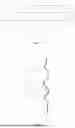
FIG. 13 is a schematic structural diagram of the bristle.
FIG. 14 is a schematic structural diagram of the installation structure of the brush roller on a production line.
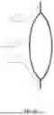
FIG. 15 is a schematic diagram showing the spacing structure as a single bending structure.
FIG. 16 is a schematic diagram showing the spacing structure as a hollow expanded structure.
FIG. 17 is a schematic diagram showing the spacing structure as a sleeve.
FIG. 18 is a schematic structural diagram of the roller body, without showing the bristles installed in the guide groove bodies.
In the drawings, the reference numerals correspond to the following technical features: roller body 1, bristle 2, roller sleeve 3, fixing bolt 5, rotation axis 101, power member 102, root segment 201, head segment 202, spacing segment 203, outer fixing member 301, roller mounting member 302, suspension plate 303, hanging lugs 304, end handle 305, side handles 306, auxiliary fixing member 307, suspension groove 401, inner fixing member 402, plate body 403, auxiliary receiving member 404, main space 401a, side spaces 401b, upper plate 403a, side plates 403b, lower plate 403c.
DETAILED DESCRIPTION OF THE EMBODIMENTS
The following provides a further detailed description of the present disclosure in conjunction with the drawings. It should be understood that the following embodiments are only used to illustrate the present disclosure and are not intended to limit the scope of the present disclosure.
FIG. 1 illustrates the brush roller described herein, the brush roller comprising: a roller body 1, bristles arranged in an annular array on the surface of the roller body 1, a roller sleeve 3 detachably and rotatably connected to the roller body 1, and a suspension component 4 slidably clamping the roller sleeve 3. The figure shows that the suspension component 4 is a groove body with a downward opening, and the groove opening has inwardly extending plates to precisely support the outwardly extending lugs of the roller sleeve 3. Below the roller sleeve 3, there is a rotatable mounting component aligned with the axis of the roller body 1.
FIG. 2 shows the structure range of the roller sleeve 3 more clearly after removing the suspension component 4 from FIG. 1.
FIG. 3 illustrates the position of the power member 102 described herein, the power member 102 being disposed at the opposite end of the roller body 1 from the rotatable mounting component on which the roller sleeve 3 is installed. In the figure, the diameter of the power member 102 is larger than the cross-sectional diameter of the roller body 1, completely covering the roller body 1. The figure also shows the auxiliary fixing member 307 on the roller sleeve 3, the auxiliary fixing member 307 being disposed on both sides above the end of the roller sleeve body where the power member 102 is located.
FIG. 4 illustrates the specific structure of the suspension component 4 described herein. It can be seen that the main body of the suspension component 4 is formed by a plate body 403, which is divided into an upper plate 403a disposed at the top, side plates 403b on both sides of the upper plate 403a, and a lower plate 403c disposed below each side plate 403b. The upper plate 403a, side plates 403b, and lower plate 403c are generally integrally formed to constitute the plate body 403, but they can also be formed by welding or bolting separately. Inner fixing members 402 are provided on the top surface of the lower plate 403c, located on the left and right sides inside the plate body 403. The dashed lines in the figure indicate the main space 401a and side spaces 401b formed by the plate body 403.
FIG. 5 illustrates the position of the rotation axis 101 on the side of the roller body 1 and the bristles 2 arranged in an annular array on the outer annular surface of the roller body 1. For ease of observing the annular arrangement of the bristles 2, only one layer of bristles 2 is shown in the figure, and the diameter of the bristles 2 relative to the diameter of the roller body 1 is intentionally enlarged for illustrative purposes, not representing the standard proportion.
FIG. 6 illustrates the specific structure of the roller sleeve, including a suspension plate 303 at the upper layer, a roller mounting member 302 disposed below the suspension plate 303, hanging lugs 304 disposed on both sides of the suspension plate 303, outer fixing members 301 disposed below each hanging lug 304, and an end handle 305 disposed at the outer end of the suspension plate 303.
FIG. 7 illustrates the vertical cross-section of the roller sleeve, more clearly showing the structure of the hanging lugs 304 extending from both sides of the suspension plate 303.
FIGS. 8, 9, and 10 illustrate the installation of the roller sleeve 3 on the suspension component 4, with the figures showing a partial view of the roller sleeve 3 and the suspension component 4 to more clearly depict the connection between the outer fixing member 301 and the inner fixing member 402. In FIG. 8, it can be seen that the bottom surface of the outer fixing member 301 contacts the upper surface of the lower plate 403c, and the bottom surface of the hanging lug 304 contacts the upper surface of the inner fixing member 402. The side of the hanging lug 304 is also provided with a side handle 306.
FIGS. 11 and 12 illustrate the installation of the roller sleeve 3 on the suspension component 4, with the figures showing a partial view of the roller sleeve 3 and the suspension component 4 to more clearly depict the connection between the auxiliary fixing member 307 and the auxiliary receiving member 404. The figures also show the distal portion structure of the inner fixing member 402.
FIG. 13 illustrates the specific structure of the bristle 2, including a head segment 202, a spacing segment 203, and a root segment 201 arranged sequentially from top to bottom, wherein the spacing structure of the spacing segment 203 comprises multiple bending structures.
FIG. 14 illustrates a schematic diagram of the installation structure of the brush roller formed by the roller body 1 with bristles 2 on a production line, with a panel forming a three-dimensional wood grain surface located below the roller body 1, and an arrow indicating the movement direction of the production line.
FIG. 15 illustrates another specific structure of the bristle 2, wherein the spacing structure of the spacing segment 203 is a single bending structure.
FIG. 16 illustrates another specific structure of the bristle 2, wherein the spacing structure of the spacing segment 203 is an enlarged portion. When the enlarged portion is provided, the bristle body does not bend but forms a structure expanding to both sides at the spacing segment 203, which is the enlarged portion to space apart at least one adjacent bristle. The enlarged portion can be a hollow structure or a solid structure.
FIG. 17 illustrates another specific structure of the bristle 2, wherein the spacing structure of the spacing segment 203 is a composite structure formed by a sleeve 204 and the middle portion of the bristle body.
FIG. 18 illustrates a three-dimensional schematic diagram of the roller body 1, mainly showing multiple guide groove bodies 103 formed or mounted on the surface of the roller body 1 for installing bristles 2.
<Structure and Function of Bristle 2>
A bristle 2, disposed on a roller with a rotation axis, for use in the process of forming textures on a board surface, comprising:
-
- A general root segment 201 for mounting on the roller;
- A general head segment 202 extending outward approximately perpendicular to the direction of the rotation axis;
- A spacing segment 203 disposed between the general root segment and the general head segment and used to isolate the distance between adjacent bristles.
Referring to FIG. 13, a spacing structure of the spacing segment 203 formed by bending deformation of the bristle body is shown, the spacing structure comprising several protrusions extending outward. These protrusions can contact the protrusions of adjacent bristles, thereby spacing apart the head segments 202 of the bristles or generating a stress for mutual separation. It can be seen that during the preparation of the spacing structure, there is a certain randomness (e.g., wire drawing or non-directional pressing), making the spacing structures between each bristle different, thus preventing the spacing structures from fitting together precisely and causing dense contact between bristles, which would lead to failure of the spacing structure.
Referring to FIG. 15, another spacing structure is shown, wherein the spacing structure of each bristle is a single arc-shaped structure protruding in the vertical direction of the bristle extension direction, formed by drawing or pressing. Since the shapes of the production molds are the same or similar, the spacing structures have the same shape. However, by varying the installation angle of the general root segment 201, the orientation of each spacing structure can be different, similarly avoiding the situation where multiple spacing structures stack together.
Referring to FIG. 16, another spacing structure is shown, wherein the spacing structure is formed by a cavity inside the bristle 2 body, expanding outward. Due to the inherent properties of the bristle material, the spacing structure has a certain degree of elasticity, and the spacing structure has a larger diameter than the general head segment and the general root segment. By occupying part of the space below the general head segment, the spacing structure causes the general head segments to be separated from each other. Another advantage of this structure is that it eliminates the possibility of multiple spacing structures stacking together.
Referring to FIG. 17, another spacing structure is shown, wherein the bristle 2 comprises a bristle body and a sleeve 204, the sleeve being sleeved on the outside of the bristle body to form the spacing structure. The material of the spacing structure can be the same as that of the bristle (if the bristle material itself has good elasticity) or made of a different material from the bristle. It can be seen that in this embodiment, the general root segment and the general head segment are portions of the bristle body exposed outside the spacing structure, meaning that the bristle body is not subjected to drawing or pressing processes. This has the advantage that the general root segment and the general head segment are always on the same straight line in the bristle extension direction. When the specific position of the general root segment is determined, the specific position of the general head segment is also determined, improving the uniformity of bristle distribution during use.
<Correlation between External Contour One Z of General Head Segment and Wire-Drawing Capability>
Bristles with different diameters were used at the same distribution density to perform wire drawing on panels coated with the same amount of base agent and polymerization inhibitor and cured for the same time. The residual amount of slow-curing substance after wire drawing was evaluated to obtain the wire-drawing capability α, in %, calculated by the following formula:
α = ( 1 - D 1 / D 0 ) × 100 %
-
- Where:
- α, wire-drawing capability, %;
- D1, total mass of residual slow-curing substance on the panel after wire drawing, g;
- D0, initial total mass of slow-curing substance on the panel, g;
- It can be seen that the larger the α value, the greater the wire-drawing capability, indicating a more complete removal of the slow-curing substance.
When the Z value increases, the α value first increases and then decreases with the increase in Z value. The reason is that when the Z value is very low, the mechanical strength of the bristle head segment 202 is insufficient, only capable of removing part of the slow-curing substance, and unable to remove slow-curing substances with a higher degree of curing. When the Z value is very high, the external contour of the bristle head segment 202 is too large to reach fine gaps formed after complete curing of the curable substance, leaving the slow-curing substance in these gaps unremovable by the bristles. Therefore, there exists a specific Z value or range that allows the bristles to have the maximum removal efficiency, i.e., a approaching 100%.
In tests, it was found that when Z=0.5-1 mm, α is approximately 100%, meaning that nearly all slow-curing substances were removed during the wire-drawing process.
<Correlation Between External Contour Two C of Spacing Segment 203 and Wire-Drawing Capability>
Bristles with different diameters C were used at the same distribution density to perform wire drawing on panels coated with the same amount of base agent and polymerization inhibitor and cured for the same time. The wire-drawing capability α was evaluated, and it was found that as the C value increases, the wire-drawing capability α first increases and then decreases. The reason is that when the C value is very small, the general head segments 202 are not spaced far apart and pile up together, making it impossible to remove slow-curing substances in fine gaps in a timely manner. When the C value is very large, the general head segments 202 are spaced too far apart, resulting in a distribution that is too sparse to clean all gaps, leading to residual slow-curing substances.
Additionally, there exists a critical value for C. When this critical value is exceeded, the bristles cannot be smoothly installed on the roller body because overly thick spacing segments prevent the bristles from being installed together.
In tests, it was found that when C=2-3 mm, α is approximately 100%, meaning that nearly all slow-curing substances were removed during the wire-drawing process.
Additionally, in tests, it was found that when C>5 mm, the bristles could not be smoothly installed on the brush roller, and the wire-drawing capability sharply declined.
<Correlation Between Diameter C of Spacing Segment 203 and Adhesion Capability of Slow-Curing Substance on General Head Segment>
Panels coated with the same amount of base agent and polymerization inhibitor and cured for the same time were passed through a brush roller at the same rotation speed. The total mass of slow-curing substance adhered to the general head segment was collected. A higher mass indicates a higher adhesion capability of the slow-curing substance on the general head segment, and correspondingly, a lower cleaning capability β. β is an empirical value negatively linearly correlated with the total mass of slow-curing substance adhered to the general head segment.
Wherein, the diameter C of the spacing segment refers to the diameter of the smallest circle that can completely cover the vertical projection of the spacing segment. From the experimental results, within the allowable range of C values, as the C value increases, the β value continuously decreases, indicating that the separated general head segments 202 have a lower tendency to adhere to the slow-curing substance.
In tests, it was found that when C=3 mm, the bristles could achieve the best wire-drawing effect and relatively low adhesion capability to the slow-curing substance.
A brush roller, comprising the aforementioned bristles; the brush roller further comprising:
-
- A roller body having a cylindrical structure and a rotation axis arranged along the axis of the cylinder;
- Guide groove bodies formed on the surface of the roller body, with the groove openings facing outward and used for mounting the general root segment of the bristles.
The guide groove bodies are circumferentially arranged on the surface of the roller body. FIG. 18 shows a state of arrangement of the guide groove bodies, wherein each guide groove body is a closed-loop structure sleeved on the roller body.
Additionally, the guide groove bodies can also be formed by hollowing out the surface of the roller body.
Referring again to FIG. 18, it can be seen that the guide groove bodies form a bristle space, which refers to the portion of the roller body not provided with bristles. Due to the presence of the bristle space, the bristles are arranged on the roller body in an array along the running direction of the production line.
<Correlation Between Bristle Space B Width and Adhesion Capability of Slow-Curing Substance on General Head Segment>
Panels coated with the same amount of base agent and polymerization inhibitor and cured for the same time were passed through brush rollers with different bristle space B widths. The total mass of slow-curing substance adhered to the general head segment was collected. A higher mass indicates a higher adhesion capability of the slow-curing substance on the general head segment, and correspondingly, a lower cleaning capability β. Experimental results showed that the β value decreases as the bristle space B increases. When β>1 mm, the β value begins to decrease and stabilizes at a specific value, approximately at B=20 mm, indicating that the bristle space B can reduce the tendency of the head segment 202 to adhere to the slow-curing substance to a certain extent. However, there is an improvement limit for B, particularly when B>20 mm, where obvious gaps exist between the bristles, and the panel in these gaps cannot be subjected to the wire-drawing process from the brush roller, leading to partial functional loss of the brush roller.
<Specific Structure and Function of Brush Roller>
Referring to FIG. 1, a brush roller comprising:
-
- A roller body 1 having a cylindrical structure and a rotation axis 101 arranged along the centerline of the cylinder;
- Bristles disposed on the surface of the roller body 1;
- A roller sleeve 3 for rotatably mounting the rotation axis 101 and provided with an outer fixing member 301;
- A suspension component 4 disposed above a conveyor belt in a production line, the suspension component 4 being provided with a suspension groove 401 for slidably mounting the roller sleeve 3 along the extension direction of the rotation axis 101, and the suspension groove 401 being configured with an inner fixing member 402 for fixing the outer fixing member 301.
The bristles are uniformly arranged on the outer annular surface of the roller body 1, and the extension direction of each bristle is substantially aligned with the axis of the roller body, so that the bristles can vertically contact the panel to be drawn when moving to the lowest point.
The rotation axis 101 is arranged along the axial direction of the roller body 1, as shown in FIG. 5.
The roller sleeve 3 is provided with a rotatable structure for mounting the rotation axis 101, such as a bearing.
The components of the roller sleeve 3 can be connected by welding, and some components can also be connected by bolts to facilitate size adjustments to fit the suspension component 4.
Wherein, the suspension component 4 is a groove body with a downward opening, the groove opening contracting inward, and the upper end of the roller sleeve 3 expanding outward to slidably fit into the inward-contracted portion of the groove opening, which can support the roller sleeve 3 and the roller body 1 mounted thereon in the vertical direction.
Once the inner fixing member 402 and the outer fixing member 301 are connected, they prevent the roller sleeve 3 from sliding in the suspension component 4, restricting the movement of the roller sleeve 3 and the roller body 1 mounted thereon in the horizontal direction, thereby limiting the movement trend of the roller body 1 except for rotation along the axial direction, achieving the fixation of the roller body 1.
Referring to FIG. 2, the effect of disassembling the roller sleeve 3 from the suspension component 4 is shown to more clearly illustrate the connection method between the roller sleeve 3 and the roller body 1. In this embodiment, the lateral distance of the upper end of the roller sleeve 3 is longer than the diameter of the brush roller formed by the roller body 1 and bristles, meaning that after the roller sleeve 3 is disassembled from the suspension component 4, other devices with fixed ends can immediately fix the outwardly extending portions of the upper end of the roller sleeve 3, achieving quick fixing, transfer, and storage functions for the roller body 1.
Referring to FIG. 4, the suspension groove 401 comprises a main space 401a and side spaces 401b extending from the main space 401a to both sides; the inner fixing member 402 is disposed inside the suspension component 4 and configured in the side spaces 401b.
The suspension component 4 comprises a plate body 403 for forming the suspension groove 401, the plate body 403 comprising an upper plate 403a, side plates 403b disposed at both side ends of the upper plate 403a, and a lower plate 403c disposed at the lower end of the side plates 403b; the upper plate 403a comprises upper plate side regions vertically opposite to the lower plate 403c, and an upper plate middle region located between the two upper plate side regions; the upper plate side regions, side plates 403b, and lower plate 403c define the side spaces 401b, and the upper plate middle region defines the main space 401a.
Wherein, the upper plate 403a, side plates 403b, and lower plate 403c may be in an assembled relationship or integrally formed as parts of the plate body 403. When the plate body 403 is integrally formed, the upper plate 403a, side plates 403b, and lower plate 403c are merely used to indicate different parts of the plate body 403 itself.
The inner fixing member 402 is disposed on the upper end surface of the lower plate 403c.
Referring to FIG. 6, the roller sleeve 3 comprises a roller mounting member 302 for rotatably mounting the rotation axis 101, a suspension plate 303 for mounting the roller mounting member 302, and hanging lugs 304 disposed on both sides of the suspension plate 303; the outer fixing member 301 is disposed on the lower end surface of the hanging lugs 304.
Wherein, during the process of slidably mounting the roller sleeve 3 into the suspension component 4, the following events occur sequentially:
-
- T11. The suspension plate 303 remains in the main space 401a, and the hanging lugs 304 on both sides of the suspension plate 303 remain in the side spaces 401b;
- T12. Continue sliding the roller sleeve 3 inward, the hanging lugs 304 on both sides of the suspension plate 303 simultaneously contact the upper edge of the inner fixing member 402, achieving the vertical support function of the suspension component 4 for the roller sleeve 3;
- T13. Continue sliding the roller sleeve 3 inward, since the outer fixing member 301 and the inner fixing member 402 have substantially the same height, the outer fixing member 301 also contacts the upper edge of the lower plate 403c, at which point the inner fixing member 402 and the upper edge of the lower plate 403c simultaneously support the roller sleeve 3, with the positional relationship between the outer fixing member 301 and the inner fixing member 402 as shown in FIG. 8;
- T14. Continue sliding the roller sleeve 3 inward, the outer fixing member 301 abuts against the inner fixing member 402, at which point the roller sleeve 3 cannot be slid further inward, completing the installation process of the roller sleeve 3 in the suspension component 4, i.e., the outer fixing member 301 and the hanging lugs 304 form a mounting contour configured to match the shape of the inner fixing member 402. The positional relationship between the outer fixing member 301 and the inner fixing member 402 is shown in FIG. 9.
Continuing to refer to FIGS. 8-9, the outer fixing member 301 and the inner fixing member 402 are respectively configured with fixing holes of the same specification, fixed simultaneously by a fixing bolt 5.
The fixing holes have a central axis parallel to the axial direction of the roller body 1, meaning that when the outer fixing member 301 abuts against the inner fixing member 402, the two fixing holes form a complete fixing hole, facilitating direct installation of the fixing bolt 5, as shown in FIG. 10.
The fixing hole on the inner fixing member 402 does not need to penetrate the entire inner fixing member 402, but only needs to be designed according to the actual length of the fixing bolt 5. The fixing hole in the outer fixing member 301 must penetrate the entire outer fixing member 301 to facilitate the installation of the fixing bolt 5 at the outer end and connection with the fixing hole on the inner fixing member 402 at the inner end.
The inner fixing member 402 should extend to the distal end of the lower plate 403c to provide sufficient support for the hanging lugs 304 throughout the entire sliding installation process of the roller sleeve 3. The inner fixing member 402 may consist of multiple members intermittently disposed along the lower plate 403c, with the fixing hole provided only in the innermost inner fixing member 402.
Wherein, the fixing bolt 5 can fix the outer fixing member 301 and the inner fixing member 402 by screwing, i.e., the fixing holes are provided with internal fixing threads, and the fixing bolt 5 is provided with external fixing threads configured to screw with the internal fixing threads.
Referring again to FIG. 6, the roller sleeve 3 further comprises an end handle 305 disposed at the proximal end of the suspension plate 303. The role of the end handle 305 is to pull the roller body 1 outward when disassembling it from the suspension component 4 and to cooperate with the upper end surface of the inner fixing member 402 to support both ends of the roller sleeve 3 when the roller sleeve 3 is disassembled outward.
Referring again to FIGS. 8-9, the roller sleeve 3 further comprises side handles 306 disposed on the outer side of the hanging lugs 304. When using a transfer device to load the partially disassembled roller sleeve 3, it is necessary to release the support of the end handle 305, which may easily cause the roller sleeve 3 to slide outward uncontrollably, posing a safety risk. The side handles 306 can assist in supporting the side of the roller sleeve 3 during disassembly, allowing temporary release of the end handle 305 while smoothly loading the proximal end of the roller sleeve 3 into the transfer device.
Additionally, when disassembling the roller sleeve 3 outward, as nearly half of the volume of the roller sleeve 3 is removed from the suspension component 4, the center of gravity of the roller sleeve 3 approaches leaving the support area of the suspension component 4. Specifically, when the center of gravity of the roller sleeve 3 leaves the area supported by the upper end surface of the inner fixing member 402, there is a risk of tilting outward. Relying solely on one person holding the end handle 305 is insufficient to resist this overturning force. The side handles 306 on the side of the roller sleeve 3 allow workers to assist in supporting from the side, further stabilizing the outward sliding disassembly process of the roller sleeve 3.
Wherein, the side handles 306 are groove handles formed by inward recesses on the outer side of the hanging lugs 304. The advantage of groove handles is that when the roller sleeve 3 is slidably mounted into the suspension component 4, the side handles 306 are entirely located inside the hanging lugs 304, so that when the hanging lugs 304 slide on the upper end surface of the inner fixing member 402, the side does not affect its fit with the side plates 403b, or the side plates 403b can cooperate with the upper end surface of the inner fixing member 402 to restrict the sliding process of the hanging lugs 304.
Referring to FIGS. 11-12, the roller sleeve 3 further comprises an auxiliary fixing member 307 disposed at the distal end of the suspension plate 303; the suspension component 4 further comprises an auxiliary receiving member 404 disposed on the plate body 403 and used for mounting the auxiliary fixing member 307. Wherein, the auxiliary fixing member 307 and the auxiliary receiving member 404 are fixed by a plug-in method to restrict the position of the distal end of the roller sleeve 3 in both horizontal and vertical directions. This displacement does not restrict the sliding behavior of the roller sleeve 3 toward the proximal end, as this behavior is already well restricted by the fixing process of the outer fixing member 301 and the inner fixing member 402 through the fixing bolt 5. The installation process of the auxiliary fixing member 307 and the auxiliary receiving member 404 is also completed in one step by the sliding of the roller sleeve 3 toward the distal end in the suspension component 4.
Referring to FIG. 3, the distal end of the roller body 1 is further provided with a power member 102; the power member 102 provides rotational power to the roller body through a transmission member connected to a power device. The power member 102 is a turntable coaxially arranged with the roller body 1, and by driving the turntable to rotate through the transmission member, the rotation of the roller body 1 is achieved.
The transmission member is a transmission belt. Compared to transmission methods such as gears, the transmission belt is flexible, and during disassembly of the roller body 1, it is only necessary to loosen the transmission belt to remove it from the power member 102.
In summary, a disassembly method for a brush roller, comprising the following steps:
-
- S01. Remove the locking device between the inner fixing member 402 and the outer fixing member 301;
- S02. Pull the roller sleeve from the suspension groove.
In S01, it further comprises the following steps:
-
- S01-1. Remove the transmission belt from the power member 102;
- S01-2. Remove the fixing bolt 5 from the inner fixing member 402 and the outer fixing member 301;
- S01-3. Pull the roller sleeve outward from the suspension groove, causing the auxiliary fixing member 307 to be detached from the auxiliary receiving member 404.
In S02, it further comprises the following steps:
-
- S02-1. Partially pull the roller sleeve from the suspension groove and use a transfer device to support the portion of the roller sleeve protruding from the suspension groove;
- S02-2. Continue pulling the roller sleeve until the entire roller sleeve is detached from the suspension groove and completely enters the transfer device.
Additionally, in another scheme for step S02, it further comprises the following steps:
-
- S02-1. Hold the end handle 305, partially pull the roller sleeve from the suspension groove, causing the side handles 306 to move out of the suspension groove 401;
- S02-2. Hold the side handles 306 to assist the end handle 305;
- S02-3. Move the transfer device to the proximal end of the roller sleeve 3 and adjust the height of the support device on the transfer device to be level with the roller sleeve 3;
- S02-4. Release the end handle 305 and move the proximal end of the roller sleeve 3 into the transfer device through the side handles 306.
The following are only preferred embodiments of the present invention and are not intended to limit the scope of the present invention.
Embodiment 1
The device of this embodiment comprises:
Bristle 2:
The bristle 2 comprises a general root segment 201, a general head segment 202, and a spacing segment 203.
The spacing segment 203 comprises a bending structure, the bending structure having at least four bends between each general root segment 201 and general head segment 202.
The maximum dimension of the external contour one of the root segment 201 and the head segment 202 is 1 mm.
The maximum dimension of the external contour two C of the spacing segment 203 is 5 mm.
Roller Body 1:
Wherein, the roller body 1 is provided with a rotation axis 101 along the axial direction, and one end of the rotation axis 101 is provided with a power member 102.
The surface of the roller body 1 is provided with guide groove bodies 103, with a bristle space B of 15 mm between the guide groove bodies 103.
Roller Sleeve 3:
The roller sleeve 3 comprises two outer fixing members 301, hanging lugs 304 respectively mounting the outer fixing members 301, a suspension plate 303 for mounting the hanging lugs 304, and a roller mounting member 302 disposed below the suspension plate 303.
The roller sleeve 3 further comprises an end handle 305 disposed at the proximal end of the suspension plate 303.
The roller sleeve 3 further comprises an auxiliary fixing member 307 disposed at the distal end of the suspension plate 303.
Suspension Component 4:
The suspension component 4 comprises a plate body 403, with a suspension groove 401 formed inside the plate body 403. The plate body 403 comprises one upper plate 403a, a total of two side plates 403b disposed on both sides of the upper plate 403a, and a total of two lower plates 403c disposed at the lower end of each side plate 403b. The suspension groove 401 is defined by the upper plate side regions, side plates 403b, and lower plate 403c to form side spaces 401b, and the region below the upper plate middle region in the suspension groove 401 constitutes the main space 401a.
The suspension component 4 further comprises an auxiliary receiving member 404 disposed on the plate body 403.
Fixing bolt 5, disposed between each outer fixing member 301 and inner fixing member 402.
Embodiment 2
In this embodiment, the roller body 1, roller sleeve 3, suspension component 4, and fixing bolt 5 are the same as in Embodiment 1, with the difference being that the bristle 2 comprises a bristle body and a sleeve 204, the sleeve 204 being sleeved on the outside of the bristle body to form the spacing segment 203.
Embodiment 3
In this embodiment, the roller body 1, roller sleeve 3, suspension component 4, and fixing bolt 5 are the same as in Embodiment 1, with the difference being that the spacing segment 203 of the bristle 2 is an enlarged portion.
Embodiment 4
In this embodiment, the roller body 1, roller sleeve 3, suspension component 4, and fixing bolt 5 are the same as in Embodiment 1, with the difference being that the bristle 2 comprises a bristle body and a coating, the coating covering the outside of the bristle body to form the spacing segment. The coating is natural rubber.
Embodiment 5
In this embodiment, the roller body 1, suspension component 4, fixing bolt 5, and bristle 2 are the same as in Embodiment 1, with the difference being that the roller sleeve 3 further comprises side handles 306 disposed on the outer side of the hanging lugs 304.
Additionally, in the drawings and description, the same or similar reference numerals are used as much as possible to refer to the same or similar parts or steps. The drawings are presented in a simplified form and are not drawn to precise scale. For convenience and clarity, directional terms such as top, bottom, left, right, upward, above, below, downward, rear, and front may be used in the drawings. These and similar directional terms should not be construed as limiting the scope of the present disclosure in any way.
Claims
1. A bristle tuft for removing uncured resin from the surface of a substrate, characterized in that it comprises: a plurality of bristles gathered into a tuft, wherein at least one bristle comprises: a general root segment for mounting on a roller body, and a general head segment extending in a direction perpendicular to the rotation axis of the roller body, and a spacing segment disposed between the general root segment and the general head segment and used to space apart at least one adjacent bristle to form a separated state except for the general root segment, the spacing segment having a spacing structure.
2. The bristle tuft according to claim 1, characterized in that the material of the bristles is metal.
3. The bristle tuft according to claim 1, characterized in that the spacing structure is formed by bending part or all of the bristle body of the spacing segment.
4. The bristle tuft according to claim 3, characterized in that the bending is a spiral bending, and the spiral coils are sequentially arranged along the extension direction of the bristle.
5. The bristle tuft according to claim 1, characterized in that the spacing structure of the spacing segment is an enlarged portion where the bristle diameter in the spacing segment is significantly larger than the bristle diameter of the general root segment.
6. The bristle tuft according to claim 1, characterized in that the spacing structure is a sleeve fixed on the spacing segment of the bristle, the sleeve being sleeved on the outside of the bristle.
7. The bristle tuft according to claim 1, characterized in that the maximum dimension of the external contour one of the general root end and the general head end is 2 mm.
8. The bristle tuft according to claim 7, characterized in that the external contour one is 0.5-1 mm.
9. The bristle tuft according to claim 1, characterized in that the maximum dimension of the external contour two of the spacing segment is 5 mm.
10. The bristle tuft according to claim 9, characterized in that the external contour two is 2-3 mm.
11. The bristle tuft according to claim 1, characterized in that the spacing structure is a coating covering the spacing segment of the bristle.
Images & Drawings included:


Sources:
- United States Patent and Trademark Office - verify current appl. status at the USPTO↗
Recent applications in this class:
- » 20240381995 2024-11-21
BRUSH FOR A SONIC TOOTHBRUSH WITH LONGITUDINAL AXIS OSCILLATION - » 20240108121 2024-04-04
WASHING BRUSH - » 20220047067 2022-02-17
Device for application of a fluid product - » 20210186203 2021-06-24
GRILL CLEANER - » 20180279766 2018-10-04
CLEANING IMPLEMENT - » 20180235358 2018-08-23
TWISTED BRUSH, METHOD FOR PRODUCING A TWISTED BRUSH, AND APPARATUS FOR PRODUCING A TWISTED BRUSH - » 20180140085 2018-05-24
GRILL CLEANER INCLUDING WIRE LOOPS - » 20070192977 2007-08-23
Painting Brush - » 20060168752 2006-08-03
Vehicle cleaning element - » 20060080799 2006-04-20
Toothbrush featuring bristles with raised annular portions