VACUUM COMPRESSION BED AND COMPRESSION STORAGE METHOD
US20260102003A1
2026-04-16
19/286,448
2025-07-31
Smart Summary: A vacuum compression bed is designed to save space when not in use. It has a rectangular shape and includes a headrest at one end. Both the bed and the headrest are made from soft foam material. Before moving it, the bed can be compressed to reduce its size, making it easier to transport. This feature is especially helpful for people who need to store or move their bed. 🚀 TL;DR
Abstract:
Provided are a vacuum compression bed and a compression storage method. The vacuum compression bed includes: a cuboid-shaped bed body that is horizontally placed and a bed head that is connected to one end of the bed body. The bed body and the bed head are made of foamed sponge; and the volume can be compressed before transportation, which is convenient for transportation.
Assignee:
- Zhenhuang ZENG 1 🇨🇳 Yueyang, China
Applicant:
Interested in similar patents?
Get notified when new applications in this technology area are published.
Classification:
A47C27/088 » CPC main
Spring, stuffed or fluid mattresses or cushions specially adapted for chairs, beds or sofas; Fluid mattresses or cushions incorporating elastic bodies, e.g. foam
A47C27/082 » CPC further
Spring, stuffed or fluid mattresses or cushions specially adapted for chairs, beds or sofas; Fluid mattresses or cushions of pneumatic type with non-manual inflation, e.g. with electric pumps
A47C27/08 IPC
Spring, stuffed or fluid mattresses or cushions specially adapted for chairs, beds or sofas Fluid mattresses or cushions
Description
CROSS-REFERENCE TO RELATED APPLICATIONS
This disclosure claims priority to Chinese Patent Application No. 2024114364613, filed with the China National Intellectual Property Administration on Oct. 15, 2024, and entitled “VACUUM COMPRESSION BED AND COMPRESSION STORAGE METHOD”, which is incorporated herein by reference in its entirety.
TECHNICAL FIELD
This disclosure relates to the field of furniture manufacturing, and in particular, to a vacuum compression bed and a compression storage method.
BACKGROUND
In terms of materials used in traditional beds, wood, plywood, nails, hardware, screws, glue, silk floss, sponge, down feather, leather, cloth, and the like are needed. There are many procedures, and a certain amount of formaldehyde is released. In terms of installation, specialized installation drawings and installation guidance videos are required, and the problem of omitted and wrong installation often occurs, resulting in after-sales problems.
In the process of implementing this disclosure, the applicant found that there are at least the following problems in the prior art:
-
- many materials are used, the structure is complex, there are many installation procedures, wrong and omitted installation easily occurs, the volume is large, and the carrying is difficult.
SUMMARY
Embodiments of this disclosure provide a vacuum compression bed and a compression storage method, to solve problems that a traditional bed uses many materials, is complex in structure, has many installation procedures, is prone to wrong and omitted installation, is large in volume, and is difficult to carry.
To achieve the above purpose, according to an aspect, an embodiment of this disclosure provides a vacuum compression bed, including: a bed body that is horizontally placed and a bed head that is connected to one end of the bed body, where
-
- the bed body and the bed head are made of foamed sponge.
Further, the foamed sponge is specifically pure high-density foamed sponge.
Further, the bed body and the bed head are obtained by performing plastic cutting on a foamed sponge raw material.
Further, density of the foamed sponge is greater than 22 kg/m3 and is less than and equal to 55 kg/m3.
Further, density of the foamed sponge is greater than 25 kg/m3 and is less than 33 kg/m3.
Preferably, density of the foamed sponge is 28 kg/m3.
Further, the bed body and the bed head are integrally formed.
Further, the bed body and the bed head are detachably connected.
Further, a plurality of half-cylindrical bulge structures that are parallel to each other are uniformly disposed on an upper surface of the bed body; and a plurality of vertical half-cylindrical bulge structures that are parallel to each other are uniformly disposed on four side vertical surfaces of the bed body.
Further, an upper portion facing one side of the bed body of the bed head is uniformly divided into a plurality of zones, and each zone is provided with a protruding arc surface structure.
According to another aspect, an embodiment of this disclosure provides a compression storage method of a vacuum compression bed, used to compress and store the foregoing vacuum compression bed, including:
-
- storing the vacuum compression bed in a vacuum storage bag made of a thermoplastic packaging material, where the vacuum storage bag is made of an airtight material;
- placing the vacuum storage bag storing the vacuum compression bed in a compression plastic packaging machine for volume compression, and performing plastic packaging on the vacuum storage bag, to enable the vacuum compression bed to be compressed to a sheet-shaped body with a certain thickness and to be kept sheet-shaped in a vacuum state formed by the vacuum storage bag, thereby obtaining a sheet-shaped package of the vacuum compression bed; and placing the sheet-shaped package of the vacuum compression bed on a crimper for crimping, to obtain a tubular package of the vacuum compression bed.
The above technical solutions have the following beneficial effects: since a sponge technique is used for plasticizing a bed shape, the single material is used, the processing technique is simple, and the obtained bed shape is stable. The volume of a sponge material can be significantly reduced after vacuum compression, which is convenient for storage and transportation. After being released from a vacuum compression state, the sponge material can automatically recover to the bed body in a use state, achieving technical effects that the single material is used, the manufacturing technique is simple, no installation is required, occupied space during transportation after compression is small, and storage is easy.
BRIEF DESCRIPTION OF THE DRAWINGS
To describe the technical solutions in the embodiments of this disclosure or in the prior art more clearly, the following briefly describes the accompanying drawings required for describing the embodiments or the prior art. Apparently, the accompanying drawings in the following description show merely some embodiments of this disclosure, and those of ordinary skill in the art may derive other drawings from these accompanying drawings without creative efforts.
FIG. 1 is a schematic structural diagram of a vacuum compression bed according to an embodiment of this disclosure;
FIG. 2 is another three-dimensional schematic diagram of a vacuum compression bed according to an embodiment of this disclosure; and
FIG. 3 is a flowchart of a compression storage method of a vacuum compression bed according to an embodiment of this disclosure.
DETAILED DESCRIPTION OF THE EMBODIMENTS
The following clearly and completely describes the technical solutions in the embodiments of this disclosure with reference to the accompanying drawings in the embodiments of this disclosure. Apparently, the described embodiments are merely some rather than all of the embodiments of this disclosure. Based on the embodiments in this disclosure, all other embodiments acquired by those of ordinary skill in the art without making creative efforts shall fall within the protection scope of this disclosure.
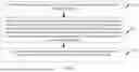
According to an aspect, as shown in FIG. 1, an embodiment of this disclosure provides a vacuum compression bed, including: a bed body 1 that is horizontally placed and a bed head 2 that is connected to one end of the bed body.
The bed body 1 and the bed head 2 are made of foamed sponge.
A shape of the bed body 1 includes but is not limited to a cuboid shape, a cylinder shape, an elliptic cylinder shape, or other shape structures that have an upper side bearing surface and a lower side support surface. A shape of the bed head 2 includes but is not limited to a cuboid shape, a half-cylinder shape, a half-elliptic cylinder shape, or the like. A side edge portion of the bed body 1 may be provided with a cuboid-shaped guardrail 11.
The embodiment of this disclosure has the following technical effects: the vacuum compression bed uses a foamed sponge technique, which can use the most advanced vacuum compression technology, eliminates cumbersome processing procedures, can be more perfectly displayed in appearance and quality, and is convenient for transportation and carrying. The compressed volume is only 15% to 20% of a conventional bed, and no installation is required. The vacuum compression bed automatically recovers to an original shape after the compression bag is unfastened. Since a sponge technique is used for plasticizing a bed shape, the single material is used, the processing technique is simple, and the obtained bed shape is stable. The volume of a sponge material can be significantly reduced after vacuum compression, which is convenient for storage and transportation. After being released from a vacuum compression state, the sponge material can automatically recover to the bed body in a use state, achieving technical effects that the single material is used, the manufacturing technique is simple, no installation is required, occupied space during transportation after compression is small, and storage is easy.
Further, the foamed sponge is specifically pure high-density foamed sponge.
The vacuum compression bed uses the pure high-density foamed sponge, so that the vacuum compression bed has good support and has high compressibility under compression of a vacuum compression device.
Further, the bed body 1 and the bed head 2 are obtained by performing plastic cutting on a foamed sponge raw material.
A cutting tool may be used to perform the plastic cutting on the block-shaped foamed sponge raw material, to obtain the vacuum compression bed. The single raw material is used, the production technique is simple, and the shape plasticity of the vacuum compression bed is strong, which is convenient for designing and manufacturing various vacuum compression beds with creative styles, thereby enhancing aesthetics and attraction of the vacuum compression bed.
Further, density of the foamed sponge is greater than 22 kg/m3 and is less than and equal to 55 kg/m3.
Further, density of the foamed sponge is greater than 25 kg/m3 and is less than 33 kg/m3.
Preferably, density of the foamed sponge is 28 kg/m3.
Further, the bed body 1 and the bed head 2 are integrally formed.
An integrally-formed manner allows for immediate use immediately after release.
Further, the bed body 1 and the bed head 2 are detachably connected.
The bed body and the bed head may be compressed together or compressed separately, thereby utilizing storage space more flexibly.
Further, as shown in FIG. 2, a plurality of half-cylindrical bulge structures that are parallel to each other are uniformly disposed on an upper surface of the bed body 1; and a plurality of vertical half-cylindrical bulge structures that are parallel to each other are uniformly disposed on four side vertical surfaces of the bed body 1.
The plurality of half-cylindrical bulge structures may enhance support of the bed body and may also be conducive to recovering from a compressed state to a use state.
Further, as shown in FIG. 2, an upper portion facing one side of the bed body 1 of the bed head 2 is uniformly divided into a plurality of zones, and each zone is provided with a protruding arc surface structure.
The protruding arc surface structure may enhance aesthetics of the bed head and facilitate leaning to improve use comfort.
According to another aspect, as shown in FIG. 3, an embodiment of this disclosure provides a compression storage method of a vacuum compression bed, used to compress and store the foregoing vacuum compression bed, including:
-
- step S10: storing the vacuum compression bed in a vacuum storage bag made of a thermoplastic packaging material, where the vacuum storage bag is made of an airtight material;
- step S11: placing the vacuum storage bag storing the vacuum compression bed in a compression plastic packaging machine for volume compression, and performing plastic packaging on the vacuum storage bag, to enable the vacuum compression bed to be compressed to a sheet-shaped body with a certain thickness and to be kept sheet-shaped in a vacuum state formed by the vacuum storage bag, thereby obtaining a sheet-shaped package of the vacuum compression bed; and
- step S12: placing the sheet-shaped package of the vacuum compression bed on a crimper for crimping, to obtain a tubular package of the vacuum compression bed.
The embodiment of this disclosure has the following technical effects: the volume of a sponge material can be significantly reduced after vacuum compression, which is convenient for storage and transportation. After being released from a vacuum compression state, the sponge material can automatically recover to the bed body in a use state, achieving technical effects that the single material is used, the manufacturing technique is simple, no installation is required, occupied space during transportation after compression is small, and storage is easy.
It should be understood that the specific order or hierarchy of steps in the processes disclosed are examples of exemplary methods. Based on design preferences, it should be understood that the specific order or hierarchy of steps in the process may be rearranged without departing from the protection scope of this disclosure. The appended method claims present elements of various steps in an exemplary order, and are not intended to be limited to the specific order or hierarchy.
In the above detailed description, various features are combined in a single embodiment, to simplify this disclosure. This method of disclosure should not be interpreted as reflecting an intention that the embodiments of the claimed subject matter require more features than those expressly described in each claim. Rather, as the appended claims reflect, this disclosure is in a state where the features are less than all features of a single embodiment disclosed. Therefore, the appended claims are hereby expressly incorporated into the detailed description, where each claim is independently used as a separate preferred embodiment of this disclosure.
To enable a person skilled in the art to implement or use this disclosure, the above description describes the disclosed embodiments. For a person skilled in the art, various modifications to these embodiments are apparent, and the generic principles defined in this disclosure may be applied to other embodiments without departing from the spirit and the protection scope of this disclosure. Therefore, this disclosure is not limited to the embodiments in this disclosure but is consistent with the widest scope of the principles and novel features disclosed in this disclosure.
The above description includes examples of one or more embodiments. Certainly, it is impossible to describe all possible combinations of components or methods for the purpose of describing the above embodiments. However, those of ordinary skill in the art should understand that various embodiments may be further combined and arranged. Therefore, the embodiments described in this disclosure are intended to embrace all such changes, modifications, and variations that fall within the protection scope of the appended claims. In addition, to the extent that the term “comprise” is used in the specification or the claims, the term is intended to be inclusive in a manner similar to the term “include”. In addition, any term “or” used in the specification of the claims is intended to mean “non-exclusive or”.
In the foregoing specific implementations, the purposes, technical solutions, and beneficial effects of this disclosure are further described in detail. It should be understood that the foregoing descriptions are merely specific implementations of this disclosure, but are not intended to limit the protection scope of this disclosure. Any modification, equivalent replacement, improvement, or the like made without departing from the spirit and principle of this disclosure shall fall within the protection scope of this disclosure.
Claims
What is claimed is:1. A vacuum compression bed, comprising a bed body that is horizontally placed and a bed head that is connected to one end of the bed body, wherein
the bed body and the bed head are made of foamed sponge.
2. The vacuum compression bed according to claim 1, wherein the foamed sponge is specifically pure high-density foamed sponge.
3. The vacuum compression bed according to claim 1, wherein the bed body and the bed head are obtained by performing plastic cutting on a foamed sponge raw material.
4. The vacuum compression bed according to claim 1, wherein density of the foamed sponge is greater than 22 kg/m3 and is less than and equal to 55 kg/m3.
5. The vacuum compression bed according to claim 1, wherein density of the foamed sponge is greater than 25 kg/m3 and is less than 33 kg/m3.
6. The vacuum compression bed according to claim 1, wherein the bed body and the bed head are integrally formed.
7. The vacuum compression bed according to claim 1, wherein the bed body and the bed head are detachably connected.
8. The vacuum compression bed according to claim 1, wherein a plurality of half-cylindrical bulge structures that are parallel to each other are uniformly disposed on an upper surface of the bed body; and a plurality of vertical half-cylindrical bulge structures that are parallel to each other are uniformly disposed on four side vertical surfaces of the bed body.
9. The vacuum compression bed according to claim 1, wherein an upper portion facing one side of the bed body of the bed head is uniformly divided into a plurality of zones, and each zone is provided with a protruding arc surface structure.
10. A compression storage method of a vacuum compression bed, used to compress and store the vacuum compression bed according to claim 1, comprising:
storing the vacuum compression bed in a vacuum storage bag made of a thermoplastic packaging material, wherein the vacuum storage bag is made of an airtight material;
placing the vacuum storage bag storing the vacuum compression bed in a compression plastic packaging machine for volume compression, and performing plastic packaging on the vacuum storage bag, to enable the vacuum compression bed to be compressed to a sheet-shaped body with a certain thickness and to be kept sheet-shaped in a vacuum state formed by the vacuum storage bag, thereby obtaining a sheet-shaped package of the vacuum compression bed; and
placing the sheet-shaped package of the vacuum compression bed on a crimper for crimping, to obtain a tubular package of the vacuum compression bed.
Images & Drawings included:


Sources:
- United States Patent and Trademark Office - verify current appl. status at the USPTO↗
Recent applications in this class:
- » 20260102004 2026-04-16
COILED SPRING AIR MATTRESS - » 20250295245 2025-09-25
BEDDING COMPONENTS INCLUDING FLUID ABSORBING GEL BEADS - » 20250194822 2025-06-19
SPONGE, AIR MATTRESS, AND SPONGE FABRICATION PROCESS - » 20250160533 2025-05-22
THICKNESS-ADJUSTABLE AIR MATTRESS STRUCTURE - » 20240285090 2024-08-29
Inflatable Bed - » 20240115058 2024-04-11
MATTRESS REINFORCEMENT SYSTEM - » 20230148763 2023-05-18
Inflatable cushion - » 20230088072 2023-03-23
Pocketed Spring Assembly Including Liquid Pods - » 20220369827 2022-11-24
HYBRID MATTRESS - » 20220104632 2022-04-07
Sleeping pad with fast-inflation and deflation air nozzle