HIGH STRENGTH STEEL SHEET, MEMBER, AND METHODS OF PRODUCING SAME
US20260103785A1
2026-04-16
19/117,391
2023-08-28
Smart Summary: A high strength steel sheet has been developed that is very strong and has great flexibility and durability. It contains specific amounts of elements like carbon, silicon, and manganese, which help enhance its properties. The steel is made up of different structures, with a majority being martensite, which contributes to its strength. The composition also includes very low levels of impurities, ensuring high quality. Overall, this steel sheet is designed for better performance in various applications, making it suitable for demanding uses. 🚀 TL;DR
Abstract:
Provided is a high strength steel sheet having high strength and excellent component strength, ductility, stretch flangeability, bendability, and warm workability. The high strength steel sheet has a chemical composition containing, in mass %, C: 0.030% to 0.500%, Si: 0.01% to 2.50%, Mn: 0.10% to 5.00%, P: 0.100% or less, S: 0.0200% or less, Al: 1.000% or less, N: 0.0100% or less, and O: 0.0100% or less, with the balance being Fe and inevitable impurity. At a ¼ sheet thickness position, the steel microstructure is such that area fractions are 60% or more martensite, 40% or less ferrite, and 20% or less retained austenite, and the lattice constant aM of martensite satisfies the following
1. 0 0 0 0 5 ≤ a M / a R ≤ 1.005 . Expression
Inventors:
- Hidekazu MINAMI 33 🇯🇵 Chiyoda-ku, Tokyo, Japan
- Yuki TOJI 49 🇯🇵 Chiyoda-ku, Tokyo, Japan
- Yusuke Wada 9 🇯🇵 Chiyoda-ku, Tokyo, Japan
Assignee:
- JFE Steel Corporation 755 🇯🇵 Chiyoda-ku, TOKYO, Japan
Applicant:
Interested in similar patents?
Get notified when new applications in this technology area are published.
Classification:
C22C38/04 » CPC main
Ferrous alloys, e.g. steel alloys containing manganese
C21D6/005 » CPC further
Heat treatment of ferrous alloys containing Mn
C21D8/0226 » CPC further
Modifying the physical properties by deformation combined with, or followed by, heat treatment during manufacturing of plates or strips characterised by the working steps Hot rolling
C21D8/0236 » CPC further
Modifying the physical properties by deformation combined with, or followed by, heat treatment during manufacturing of plates or strips characterised by the working steps Cold rolling
C21D8/0273 » CPC further
Modifying the physical properties by deformation combined with, or followed by, heat treatment during manufacturing of plates or strips characterised by the heat treatment Final recrystallisation annealing
C21D9/46 » CPC further
Heat treatment, e.g. annealing, hardening, quenching or tempering, adapted for particular articles; Furnaces therefor for sheet metals
C22C38/001 » CPC further
Ferrous alloys, e.g. steel alloys containing N
C22C38/002 » CPC further
Ferrous alloys, e.g. steel alloys containing In, Mg, or other elements not provided for in one single group -
C22C38/02 » CPC further
Ferrous alloys, e.g. steel alloys containing silicon
C22C38/06 » CPC further
Ferrous alloys, e.g. steel alloys containing aluminium
C23C2/06 » CPC further
Hot-dipping or immersion processes for applying the coating material in the molten state without affecting the shape; Apparatus therefor characterised by the coating material Zinc or cadmium or alloys based thereon
C23C2/12 » CPC further
Hot-dipping or immersion processes for applying the coating material in the molten state without affecting the shape; Apparatus therefor characterised by the coating material Aluminium or alloys based thereon
C21D2211/001 » CPC further
Microstructure comprising significant phases Austenite
C21D2211/005 » CPC further
Microstructure comprising significant phases Ferrite
C21D2211/008 » CPC further
Microstructure comprising significant phases Martensite
C21D6/00 IPC
Heat treatment of ferrous alloys
C21D8/0221 IPC
Modifying the physical properties by deformation combined with, or followed by, heat treatment during manufacturing of plates or strips characterised by the working steps
C21D8/0247 IPC
Modifying the physical properties by deformation combined with, or followed by, heat treatment during manufacturing of plates or strips characterised by the heat treatment
C22C38/00 IPC
Ferrous alloys, e.g. steel alloys
Description
TECHNICAL FIELD
The present disclosure relates to a high strength steel sheet, a member, and methods of producing same.
BACKGROUND
Higher strength steel sheets for automobiles are being developed to both reduce CO2 emissions by reducing vehicle weight and improve crashworthiness by reducing automotive body weight. New laws and regulations concerning automobiles are also being introduced one after another.
For the purpose of increasing automotive body strength, high strength cold-rolled steel sheets having a tensile strength (TS) of 980 MPa or more are increasingly being applied to major structural components that form the framework of automobile cabins. Patent Literature (PTL) 1 describes a high strength cold-rolled steel sheet having a tensile strength of 1310 MPa or more. Further, in order to increase the ratio of high strength steel sheet use in automobiles, in addition to the application of hot stamping, attention is being paid to warm working, which involves forming at lower heating temperature. PTL 2 describes a high strength steel sheet for warm working that has excellent workability even at a low heating temperature from 50° C. to 200° C.
CITATION LIST
Patent Literature
-
- PTL 1: WO 2019/181950 A1
- PTL 2: WO 2017/131053 A1
SUMMARY
Technical Problem
Conventionally, there has been no high strength steel sheet that has excellent ductility, stretch flangeability, and bendability at room temperature, and excellent warm workability. For example, although the high strength steel sheet of PTL 1 has excellent bendability and ductility at room temperature, no consideration is given to warm workability. Further, although the high strength steel sheet of PTL 2 has excellent warm workability (total elongation), the breakdown of uniform elongation and local elongation at warm temperatures is unclear. Further, stretch flangeability and bendability at room temperature were not considered in PTL 2.
In view of the circumstances described above, it would be helpful to provide a high strength steel sheet having a tensile strength of 980 MPa or more and excellent component strength, ductility, stretch flangeability, bendability, and warm workability, a member, and methods of producing same.
Solution to Problem
The inventors conducted extensive studies to address the technical problems described above, and as a result discovered that the following configuration can be adopted, and thus arrived at the present disclosure. Primary features of the present disclosure are as follows,
-
- [1] A high strength steel sheet comprising a chemical composition containing (consisting of), in mass %,
- C: 0.030% or more and 0.500% or less,
- Si: 0.01% or more and 2.50% or less,
- Mn: 0.10% or more and 5.00% or less,
- P: 0.100% or less,
- S: 0.0200% or less,
- Al: 1.000% or less,
- N: 0.0100% or less, and
- O: 0.0100% or less,
- with the balance being Fe and inevitable impurity, wherein
- at a ¼ sheet thickness position, the steel microstructure is such that
- an area fraction of martensite is 60% or more,
- an area fraction of ferrite is 40% or less,
- an area fraction of retained austenite is 20% or less, and
- a lattice constant aM of the martensite, in nm, satisfies the following Expression 1,
1. 0 0 0 0 5 ≤ a M / a R ≤ 1.005 Expression 1
-
- where, aR is the lattice constant of the martensite, in nm, at room temperature after heat treatment of the high strength steel sheet at 500° C. for 30 min,
- [2] The high strength steel sheet according to [1], wherein the number of martensitic blocks containing carbide having a major axis length of 200 nm or more is 50% or less of the number of martensitic blocks containing carbide,
- [3] The high strength steel sheet according to [1] or [2], the chemical composition further containing, in mass %, at least one element selected from the group consisting of:
- Ti: 0.200% or less,
- Nb: 0.200% or less,
- V: 0.200% or less,
- Ta: 0.10% or less,
- W: 0.10% or less,
- B: 0.0100% or less,
- Cr: 1.00% or less,
- Mo: 1.00% or less,
- Ni: 1.00% or less,
- Co: 0.010% or less,
- Cu: 1.00% or less,
- Sn: 0.200% or less,
- Sb: 0.200% or less,
- Ca: 0.0100% or less,
- Mg: 0.0100% or less,
- REM: 0.0100% or less,
- Zr: 0.100% or less,
- Te: 0.100% or less,
- Hf: 0.10% or less, and
- Bi: 0.200% or less,
- [4] The high strength steel sheet according to any one of [1] to [3], further comprising a coated or plated layer on at least one side,
- [5] A member formed using the high strength steel sheet according to any one of [1] to [4],
- [6] The member according to [5], wherein the member is for an automobile frame structural component or reinforcing component,
- [7] A method of producing a high strength steel sheet, the method comprising:
- rough rolling a steel slab having the chemical composition according to [1] or [3] at an average strain rate of 1×10⁻⁴/s or more and 1×10⁻¹/s or less with a total rolling reduction of 50% or more to obtain a rough rolled sheet, then finish rolling the rough rolled sheet to obtain a hot-rolled sheet;
- cold rolling the hot-rolled sheet to obtain a cold-rolled sheet;
- annealing the cold-rolled sheet by heating to a heating temperature of 800° C. or more, and cooling under a condition that a residence time t1 in a temperature range T1 from Ms temperature to 700° C. is 1000 s or less; and
- partially tempering the cold-rolled sheet by cooling from the Ms temperature to 50° C. or less under a condition that a partial tempering parameter S, in μm2, satisfies the following Expression 2,
0 . 0 1 ≤ S ≤ 30 Expression 2 S = ∑ t = 1 t E f ( t ) D ( T ) × 10 12 Expression 3 f ( t ) = 1 - exp ( - 1.1 × 10 - 2 ( Ms - T min ) ) Expression 4 D ( T ) = 0.394 × 10 - 6 exp ( - 80220 8.314 × ( T + 273 ) ) Expression 5
-
- where, in Expressions 2 to 5,
- a time when the temperature of the cold-rolled sheet first reaches the Ms temperature after the annealing is defined as t=0, in s, and t=tE, in s, is the time when the partial tempering is completed and the temperature of the cold-rolled sheet is 50° C.,
- T, in ° C., is an average temperature of the cold-rolled sheet at time t-1 to t, in s,
- Tmin, in ° C., is the lowest temperature of T at time 0 to t, in s, and
- Ms, in ° C., indicates the Ms temperature of the high strength steel sheet,
- [8] The method of producing a high strength steel sheet according to [7], where, in the partial tempering, cooling is stopped at a cooling stop temperature that is room temperature or more and the Ms temperature or less, followed by reheating to a reheating temperature and then cooling to 50° C. or less,
- [9] The method of producing a high strength steel sheet according to [7] or [8], where, in the annealing, coating or plating treatment is further applied to at least one side of the cold-rolled sheet,
- [10] A method of producing a member, the method comprising at least one of a forming process or a joining process applied to the high strength steel sheet according to any one of [1] to [4] to obtain the member.
Advantageous Effect
According to the present disclosure, a high strength steel sheet having a tensile strength of 980 MPa or more and excellent component strength, ductility, stretch flangeability, bendability, and warm workability, a member, and methods of producing same can be provided.
BRIEF DESCRIPTION OF THE DRAWINGS
In the accompanying drawings:
FIG. 1 is a diagram illustrating an example of an electron diffraction pattern of martensite with carbide;
FIG. 2 is a schematic diagram of thermal hysteresis of a partial tempering process of continuously cooling from the Ms temperature to 50° C., and a schematic diagram of f (t); and
FIG. 3 is a schematic diagram of thermal hysteresis when reheating is carried out in partial tempering, and a schematic diagram of f (t).
DETAILED DESCRIPTION
The following describes embodiments of the present disclosure. However, the present disclosure is not limited to the following embodiments. The high strength steel sheet according to the present embodiment has the chemical composition and steel microstructure described below. Hereinafter, “high strength steel sheet” is also referred to simply as “steel sheet”.
The high strength steel sheet according to the present embodiment has a tensile strength of 980 MPa or more and excellent component strength, ductility, stretch flangeability, bendability, and warm workability.
High strength means that the tensile strength (TS) is 980 MPa or more, as determined by the tensile test described below.
Excellent component strength means that the yield ratio (YR) is 60% or more, as determined by the tensile test described below.
Excellent ductility means that the total elongation (T-El) is 6.0% or more, as determined by the tensile test described below.
Excellent stretch flangeability means that the hole expansion ratio (2) is 30% or more, as determined by the hole expanding test described below.
Excellent bendability means that the limit bending radius (R/t) is 5.0 or less, as determined by the bend test of a sample having a ground end face as described below.
Excellent warm workability means that when the uniform elongation (U-ElRT) and the local elongation (L-ElRT) are determined by the tensile test at room temperature described below, and the uniform elongation (U-El200) and the local elongation (L-El200) are determined by the tensile test at 200° C., then U-E1200/U-ElRT is 1.10 or more and L-El200/L-ElRT is 1.30 or more.
When warm working, from the viewpoint of strain dispersion capability, the uniform elongation of the steel sheet needs to be higher than at room temperature, and in order to suppress fracture of the worked portion, the local elongation of the steel sheet needs to be higher than at room temperature. In warm working, it is assumed that a press mold and a steel sheet are heated to a defined temperature for working, but end face portions of the steel sheet tend to cool down, and therefore it is assumed that the working is essentially carried out at room temperature. Therefore, in addition to excellent warm workability, the steel sheet is required to have good ductility, stretch flangeability, and bendability at room temperature. Further, high strength steel sheets used for automobile reinforcing components and frame structural components are required to have excellent component strength (high impact absorbed energy in a crash). This can be achieved by increasing the yield strength (YS) of a steel sheet or by increasing the yield ratio (YR=Yield strength YS/Tensile strength TS×100 [%]) of the steel sheet. Conventionally, there were no high strength steel sheets having good ductility, stretch flangeability, and bendability at room temperature and excellent workability at warm temperatures. In conventionally used steel sheets containing a large amount of retained austenite phase, very hard fresh martensite is formed by working by punching, and low stretch flangeability is expected in terms of void formation, growth, and consolidation. As described below, as a result of extensive studies, the inventors arrived at the idea of appropriately adjusting a partial tempering parameter S. This allows a ratio aM/aR between the lattice constant ay of martensite at room temperature and the lattice constant aR at room temperature after heat treatment of a high strength steel sheet including martensite at 500° C. for 30 min to be set to an appropriate value. By setting aM/aR to an appropriate value, it is possible to provide the high strength steel sheet having good ductility, stretch flangeability, and bendability at room temperature and excellent workability at warm temperatures.
Chemical composition
First, appropriate ranges for a chemical composition of the high strength steel sheet and reasons for such limitations are described. In the following description, “%” representing the content of a component element in the steel sheet means “mass %” unless otherwise specified.
C: 0.030% or more and 0.500% or less
C is one of the important basic components of a steel sheet, and particularly in the high strength steel sheet according to the present embodiment, C affects the area fraction of martensite and the lattice constant of martensite.
When C content is too low, the area fraction of martensite decreases, making it difficult to achieve a TS of 980 MPa or more. Further, the lattice constant aM of martensite decreases, and warm workability decreases. Further, the area fraction of ferrite increases. The C content of the steel sheet is therefore 0.030% or more. The C content is preferably 0.050% or more. The C content is more preferably 0.090% or more.
On the other hand, when the C content is too high, the retained austenite increases excessively and the hardness of the martensite formed from the retained austenite during punching increases significantly. As a result, crack propagation during hole expansion is promoted, resulting in a lower hole expansion ratio and decreased stretch flangeability. Further, stress-induced transformation of retained austenite decreases YR, resulting in lower component strength. The C content is therefore 0.500% or less. The C content is preferably 0.400% or less. The C content is more preferably 0.350% or less.
Si: 0.01% or more and 2.50% or less
Si increases the strength of the steel sheet by inhibiting the precipitation of cementite in martensite and by solid solution strengthening. To obtain this effect, Si content is 0.01% or more. Si content is preferably 0.05% or more. Si content is more preferably 0.10% or more.
On the other hand, when the Si content is too high, carbide precipitation during bainite transformation is significantly suppressed, resulting in an excessive increase in retained austenite and a large increase in the hardness of martensite formed from the retained austenite during punching. As a result, crack propagation during hole expansion is promoted, resulting in a lower hole expansion ratio and decreased stretch flangeability. Further, stress-induced transformation of retained austenite decreases YR, resulting in lower component strength. The Si content is therefore 2.50% or less. The Si content is preferably 2.00% or less. The Si content is more preferably 1.50% or less.
Mn: 0.10% or more and 5.00% or less
Mn is one of the important basic components of a steel sheet, and particularly in the high strength steel sheet according to the present embodiment, Mn affects the area fraction of martensite.
When Mn content is too low, the area fraction of martensite decreases, making it difficult to achieve a TS of 980 MPa or more. Further, the area fraction of martensite decreases, making it difficult to obtain high warm workability. The Mn content is therefore 0.10% or more. The Mn content is preferably 0.90% or more. The Mn content is more preferably 1.80% or more.
On the other hand, when the Mn content is too high, austenite stabilizes and retained austenite increases excessively. The hardness of martensite formed from retained austenite during punching is then greatly increased. As a result, crack propagation during hole expansion is promoted, resulting in a lower hole expansion ratio and decreased stretch flangeability. Further, stress-induced transformation of retained austenite decreases YR, resulting in lower component strength. The Mn content is therefore 5.00% or less. The Mn content is preferably 4.20% or less. The Mn content is more preferably 3.60% or less.
P: 0.100% or less
P segregates at prior austenite grain boundaries, embrittling grain boundaries, thereby decreasing steel sheet ultimate deformability, resulting in a decrease in λ. Further, bendability also decreases. P content therefore needs to be 0.100% or less. A lower limit of the P content is not particularly specified. P is a solid-solution-strengthening element able to increase steel sheet strength, and therefore the P content is preferably 0.001% or more. The P content is preferably 0.070% or less.
S: 0.0200% or less
S exists as a sulfide and decreases ultimate deformability of the steel sheet, resulting in a decrease in A. Further, bendability also decreases. S content therefore needs to be 0.0200% or less. A lower limit of the S content is not particularly specified. In view of production technology constraints, the S content is preferably 0.0001% or more. The S content is preferably 0.0050% or less.
Al: 1.000% or less
Al provides sufficient deoxidation and decreases inclusions in steel.
However, when Al content is too high, a large amount of ferrite is formed, resulting in a lower hole expansion ratio and decreased stretch flangeability. The Al content is therefore 1.000% or less. The Al content is preferably 0.500% or less. The Al content is more preferably 0.100% or less.
On the other hand, for stable deoxidation, the Al content is preferably 0.010% or more. The Al content is more preferably 0.015% or more. The Al content is even more preferably 0.020% or more.
N: 0.0100% or less
N exists as a nitride and decreases ultimate deformability of the steel sheet, resulting in a decrease in 2. Further, bendability also decreases. N content is therefore 0.0100% or less. A lower limit of the N content is not particularly specified. In view of production technology constraints, the N content is preferably 0.0001% or more. The N content is preferably 0.0050% or less.
O: 0.0100% or less
O exists as an oxide and decreases ultimate deformability of the steel sheet, resulting in a decrease in 2. Further, bendability also decreases. 0 content is therefore 0.0100% or less. A lower limit of the O content is not particularly specified. In view of production technology constraints, the O content is preferably 0.0001% or more. The O content is preferably 0.0050% or less.
The high strength steel sheet according to the present embodiment has a chemical composition that consists of the above components, with the balance being Fe and inevitable impurity. Examples of inevitable impurity include Zn, Pb, As, Ge, Sr, and Cs. It is acceptable for these impurities to be present for a total content of 0.100% or less.
The chemical composition of the high strength steel sheet according to the present embodiment may further contain, in mass %, at least one element, alone or in combination, selected from the group consisting of: Ti: 0.200% or less, Nb: 0.200% or less, V: 0.200% or less, Ta: 0.10% or less, W: 0.10% or less, B: 0.0100% or less, Cr: 1.00% or less, Mo: 1.00% or less, Ni: 1.00% or less, Co: 0.010% or less, Cu: 1.00% or less, Sn: 0.200% or less, Sb: 0.200% or less, Ca: 0.0100% or less, Mg: 0.0100% or less, REM: 0.0100% or less, Zr: 0.100% or less, Te: 0.100% or less, Hf: 0.10% or less, and Bi: 0.200% or less.
When Ti content, Nb content, and V content are respectively 0.200% or less, coarse precipitates and inclusions do not form in large amounts, the ultimate deformability of the steel sheet does not decrease, and therefore A does not decrease. Further, bendability does not decrease. Therefore, when Ti is contained in the steel sheet, the Ti content is preferably 0.200% or less. When Nb is contained in the steel sheet, the Nb content is preferably 0.200% or less. When V is contained in the steel sheet, the V content is preferably 0.200% or less. Lower limits of Ti, Nb, and V content are not particularly specified. Ti, Nb, and V content increases strength of the steel sheet by forming fine carbides, nitrides, and carbonitrides during hot rolling or continuous annealing, and therefore the content of each of Ti, Nb, and V is respectively more preferably 0.001% or more. The Ti content is more preferably 0.100% or less. The Nb content is more preferably 0.100% or less. The V content is more preferably 0.100% or less.
When Ta content and W content are respectively 0.10% or less, coarse precipitates and inclusions do not form in large amounts, the ultimate deformability of the steel sheet does not decrease, and therefore λ does not decrease. Further, bendability does not decrease. Therefore, Ta content is preferably 0.10% or less. W content is preferably 0.10% or less. Lower limits of Ta and W content are not particularly specified. Ta and W content increases strength of the steel sheet by forming fine carbides, nitrides, and carbonitrides during hot rolling or continuous annealing, and therefore the content of each of Ta and W is respectively more preferably 0.01% or more. The Ta content is more preferably 0.08% or less. The W content is more preferably 0.08% or less.
When B content is 0.0100% or less, cracks are not caused inside the steel sheet during casting or hot rolling and the ultimate deformability of the steel sheet is not decreased, and therefore A does not decrease. Further, bendability does not decrease. The B content is therefore preferably 0.0100% or less. A lower limit of the B content is not particularly specified. B is an element that improves hardenability by segregating to austenite grain boundaries during annealing, and therefore the B content is more preferably 0.0003% or more. The B content is more preferably 0.0080% or less.
When Cr content, Mo content, and Ni content are respectively 1.00% or less, the amount of coarse precipitates and inclusions do not increase, the ultimate deformability of the steel sheet does not decrease, and therefore 2 does not decrease. Further, bendability does not decrease. Therefore, Cr content is preferably 1.00% or less. Mo content is preferably 1.00% or less. Ni content is preferably 1.00% or less. Lower limits of Cr, Mo, and Ni content are not particularly specified. Cr, Mo, and Ni are elements that improve hardenability, and therefore the content of each of Cr, Mo, and Ni is respectively more preferably 0.01% or more. The Cr content is more preferably 0.80% or less. The Mo content is more preferably 0.80% or less. The Ni content is more preferably 0.80% or less.
When Co content is 0.010% or less, the amount of coarse precipitates and inclusions does not increase, the ultimate deformability of the steel sheet does not decrease, and therefore λ does not decrease. Further, bendability does not decrease. The Co content is therefore preferably 0.010% or less. A lower limit of the Co content is not particularly specified. Co is an element that improves hardenability, and therefore the Co content is more preferably 0.001% or more. The Co content is more preferably 0.008% or more.
When Cu content is 1.00% or less, the amount of coarse precipitates and inclusions does not increase, the ultimate deformability of the steel sheet does not decrease, and therefore λ does not decrease. Further, bendability does not decrease. The Cu content is therefore preferably 1.00% or less. A lower limit of the Cu content is not particularly specified. Cu is an element that improves hardenability, and therefore the Cu content is more preferably 0.01% or more. The Cu content is more preferably 0.80% or less.
When Sn content is 0.200% or less, cracks are not caused inside the steel sheet during casting or hot rolling and the ultimate deformability of the steel sheet is not decreased, and therefore λ does not decrease. Further, bendability does not decrease. The Sn content is therefore preferably 0.200% or less. A lower limit of the Sn content is not particularly specified. Sn is an element that improves hardenability, and therefore the Sn content is more preferably 0.001% or more. The Sn content is more preferably 0.100% or less.
When Sb content is 0.200% or less, the amount of coarse precipitates and inclusions does not increase, the ultimate deformability of the steel sheet does not decrease, and therefore λ does not decrease. Further, bendability does not decrease. The Sb content is therefore preferably 0.200% or less. A lower limit of the Sb content is not particularly specified. Sb is an element that controls surface layer softening thickness and enables strength adjustment, and therefore the Sb content is more preferably 0.001% or more. The Sb content is more preferably 0.100% or less.
When Ca content, Mg content, and REM content are respectively 0.0100% or less, the amount of coarse precipitates and inclusions does not increase, the ultimate deformability of the steel sheet does not decrease, and therefore λ does not decrease. Further, bendability does not decrease. Therefore, Ca content is preferably 0.0100% or less. Mg content is preferably 0.0100% or less. REM content is preferably 0.0100% or less. Lower limits of Ca, Mg, and REM content are not particularly specified. Ca, Mg, and REM spheroidize the shape of nitrides and sulfides and improve steel sheet ultimate deformability, and therefore the content of each of Ca, Mg, and REM is respectively preferably 0.0005% or more. The Ca content is more preferably 0.0050% or less. The Mg content is more preferably 0.0050% or less. The REM content is more preferably 0.0050% or less.
When Zr content and Te content are respectively 0.100% or less, the amount of coarse precipitates and inclusions does not increase, the ultimate deformability of the steel sheet does not decrease, and therefore A does not decrease. Further, bendability does not decrease. Therefore, Zr content is preferably 0.100% or less. Te content is preferably 0.100% or less. Lower limits of Zr and Te content are not particularly specified. Zr and Te are elements that spheroidize the shape of nitrides and sulfides and improve steel sheet ultimate deformability, and therefore the content of each of Zr and Te is respectively more preferably 0.001% or more. The Zr content is more preferably 0.080% or less. The Te content is more preferably 0.080% or less.
When Hf content is 0.10% or less, the amount of coarse precipitates and inclusions does not decrease, the ultimate deformability of the steel sheet does not decrease, and therefore A does not decrease. Further, bendability does not decrease. The Hf content is therefore preferably 0.10% or less. A lower limit of the Hf content is not particularly specified. Hf is an element that spheroidizes the shape of nitrides and sulfides and improves steel sheet ultimate deformability, and therefore the Hf content is preferably 0.01% or more. The Hf content is more preferably 0.08% or less.
When Bi content is 0.200% or less, the amount of coarse precipitates and inclusions does not increase, the ultimate deformability of the steel sheet does not decrease, and therefore λ does not decrease. Further, bendability does not decrease. The Bi content is therefore preferably 0.200% or less. A lower limit of the Bi content is not particularly specified. Bi is an element that reduces segregation, and therefore the Bi content is preferably 0.001% or more. The Bi content is more preferably 0.100% or less.
When the content of each of Ti, Nb, V, Ta, W, B, Cr, Mo, Ni, Co, Cu, Sn, Sb, Ca, Mg, REM, Zr, Te, Hf, and Bi described above is below the respective preferred lower limit, the effect of the present disclosure is not impaired, and therefore such elements are included as inevitable impurity.
Next, the microstructure of the high strength steel sheet is described.
Area fraction of martensite: 60% or more
By containing martensite, TS of 980 MPa or more and excellent warm workability become possible to realize. By increasing the area fraction of martensite, as described below, a ductility-improving mechanism caused by a microscopic interaction between a large amount of dislocations in martensite and appropriately controlled solute C can be expressed as macroscopic elongation in warm working. The area fraction of martensite is therefore 60% or more. The area fraction of martensite is preferably 70% or more. The area fraction of martensite is more preferably 90% or more.
An upper limit of the area fraction of martensite is not particularly limited, and the effects described above are obtainable even at 100%. Martensite is a transformation phase that forms at the Ms temperature or below, with or without tempering. Further, martensite includes lower bainite that forms at the Ms temperature or below.
The observed position of martensite is at the ¼ sheet thickness position, as described below.
Area fraction of ferrite: 40% or less
The desired strength and stretch flangeability are obtainable when the area fraction of ferrite is 40% or less. The effects are obtainable even when the area fraction of ferrite is 0%. When there is too much ferrite, sufficient martensite cannot be secured, and the desired TS cannot be obtained. Further, the hardness difference between microstructures increases, promoting void generation and consolidation, which reduces the hole expansion ratio and degrades stretch flangeability. The area fraction of ferrite is therefore 40% or less. The area fraction of ferrite is preferably 30% or less. The area fraction of ferrite is more preferably 20% or less.
Ferrite is a soft bcc iron that forms at temperatures higher than the Ms temperature and includes allotriomorphic ferrite, idiomorphic ferrite, and upper bainite.
The observation position of ferrite is the ¼ sheet thickness position (a position corresponding to ¼ of the thickness in the depth direction from the surface of the steel sheet), as described below.
The area fraction measurements for martensite and ferrite are as follows.
First, a sample is cut from the steel sheet so that the thickness cross-section parallel to the rolling direction (L-section at the ¼ sheet thickness position) becomes the observation plane. The sample observation plane is mirror polished with diamond paste, followed by finish polishing with colloidal silica, and then etched with 1 vol % nital to reveal the microstructure.
The sample observation plane is then observed using a scanning electron microscope (SEM) at a magnification of 3000× under the condition of an accelerating voltage of 10 kV to obtain SEM images for three fields of view.
From the obtained SEM images, the area fraction of each microstructure is calculated using Adobe Photoshop (produced by Adobe Systems). Specifically, the value obtained by dividing the area of each microstructure by the measured area is the area fraction of each microstructure. The area fraction of each microstructure is calculated for three fields of view, and the average of these is the area fraction of each microstructure.
In the SEM image, ferrite is gray in color and is a flat microstructure region that does not encapsulate carbides having a white contrast. In contrast, martensite has a hierarchical microstructure with fine internal irregularities. Thus, martensite and ferrite can be distinguished from each other.
Retained austenite area fraction: 20% or less
Good component strength and stretch flangeability are obtainable when the area fraction of retained austenite is 20% or less. The area fraction of retained austenite is therefore 20% or less. The area fraction of retained austenite is preferably 15% or less.
A lower limit of the area fraction of retained austenite is not particularly limited, and the effects described above are obtainable even at 0%.
The area fraction measurement method for retained austenite is as follows.
First, the steel sheet is ground so that the ¼ sheet thickness position becomes the measurement surface, and then the sample is further ground by 0.1 mm by chemical polishing to obtain a sample. For the sample measurement surface, the X-ray diffraction device measures the integrated reflection intensity of the (200), (220), and (311) planes of fcc iron (austenite) and the (200), (211), and (220) planes of bcc iron, using a Co Kα radiation source. The intensity ratio of the integrated reflection intensity of each plane of fcc iron to the integrated reflection intensity of each plane of bcc iron is determined. The average value of nine intensity ratios is the volume fraction of retained austenite. The volume fraction of retained austenite is considered to be the area fraction of retained austenite.
Lattice Constant of Martensite
The lattice constant of martensite is a very important microstructure factor according to the present disclosure. When the lattice constant aM (nm) of martensite at room temperature satisfies Expression 1, the high strength steel sheet having excellent ductility and bendability at room temperature, and excellent warm workability, is obtainable.
1. 0 0 0 0 5 ≤ a M / a R ≤ 1.005 Expression 1
In Expression 1, aR (nm) is the lattice constant of martensite at room temperature after heat treatment of the high strength steel sheet at 500° C. for 30 min.
The inventors found that by setting the ratio aM/aR between the lattice constant aM of martensite at room temperature and the lattice constant aR at room temperature after heat treatment of the high strength steel sheet containing the martensite at 500° C. for 30 min to an appropriate value, the steel sheet having excellent ductility at room temperature and excellent warm workability is obtainable. It is assumed that the presence of an appropriate amount of solute C in martensite that contains a large amount of dislocations responsible for plastic deformation improves both uniform elongation and local elongation during warm working due to the interaction between dislocations and solute C. The lattice constant aM of martensite is affected not only by C, which is an interstitial solute element, but also by Si and Mn, which are substitutional solute elements. By heat-treating the high strength steel sheet at 500° C. for 30 min, the solute C in martensite precipitates as cementite, and the solute C concentration becomes very low. Therefore, the ratio aM/aR between the lattice constant aM of martensite at room temperature and the lattice constant aR at room temperature after heat treatment of the high strength steel sheet including martensite at 500° C. for 30 min is a parameter that precisely represents the concentration of solute C in martensite. The concentration of solute C in martensite affects ductility at room temperature and warm workability. Therefore, by controlling aM/aR to satisfy Expression 1, the high strength steel sheet having excellent ductility and bendability at room temperature, and excellent warm workability, is obtainable.
When aM/aR is less than 1.00005, the concentration of solute C in martensite is low and the interaction between dislocations in martensite and solute C during warm working becomes small, resulting in poor warm workability. On the other hand, when aM/aR exceeds 1.00500, dislocation migration at room temperature is significantly suppressed, resulting in reduced ductility and bendability at room temperature. Therefore, the lattice constant aM of martensite needs to satisfy 1.00005≤aM/aR≤1.00500. Preferably, aM/aR is 1.00010 or more. Preferably, aM/aR is 1.00200 or less.
The lattice constant of martensite is determined by an X-ray diffraction method. The high strength steel sheet is ground so that the ¼ sheet thickness position becomes the measurement surface, and then further ground by 0.1 mm by chemical polishing to obtain a sample.
For the sample measurement surface, an X-ray diffraction device is used with a Cu Kα radiation source to calculate the peak positions by fitting the peaks of the (110), (200), (211), (220), (310), and (222) planes of bcc iron using a pseudo-Voigt approximation. From each peak position obtained, assuming that c/a is 1, the lattice constant is calculated from Bragg's law, and the average value is taken as the lattice constant aM of martensite.
The lattice constant aR of martensite is determined for the steel sheet after heat treatment at 500° C. for 30 min, in the same way as for the high strength steel sheet described above.
Ratio of number of martensitic blocks containing carbide having major axis length of 200 nm or more to number of martensitic blocks containing carbide: 50% or less
Warm workability can be further improved by reducing the ratio of the number of martensitic blocks containing carbide having a major axis length of 200 nm or more to the number of martensitic blocks containing carbide. Carbides that are 200 nm or more in martensitic blocks are thermally stable in terms of interfacial energy and are more likely to deplete surrounding solute C during warm working, resulting in a localized decrease in solute C. Uniform elongation and local elongation during warm working can be further improved by decreasing the number of martensitic blocks containing carbides that are 200 nm or more. The ratio of the number of martensitic blocks containing carbide having a major axis length of 200 nm or more to the number of martensitic blocks containing carbide is therefore preferably 50% or less. The ratio is more preferably 30% or less. The ratio is even more preferably 10% or less. The lower limit of the ratio of the number of martensitic blocks containing carbide having a major axis length of 200 nm or more to the number of martensitic blocks containing carbide is not particularly limited and may be 0%.
Carbide contained in a martensitic block is at least one of the following: cementite, epsilon carbide, eta carbide, or chi carbide.
The method of measuring the ratio of the number of martensitic blocks containing carbide having a major axis length of 200 nm or more to the number of martensitic blocks containing carbide is as follows.
First, the steel sheet is ground so that the ¼ sheet thickness position becomes the observation plane, and then the sample is electropolished. The observation plane of the prepared sample is observed using a transmission electron microscope (TEM) at an accelerating voltage of 200 kV. The dislocation density of martensite is significantly higher than that of ferrite or retained austenite, and therefore they can be distinguished from each other by observing the strain contrast in a TEM bright-field image. A martensite block is a hierarchical unit comprising martensite and is a group of laths having the same crystallographic planes and crystal orientation. Therefore, in the TEM bright-field image, the diffraction contrast differs from block to block within martensite, making it possible to distinguish other hierarchical structures such as packets and laths. When an electron beam is incident on a martensitic block in the [100] orientation, an electron diffraction pattern of the martensite matrix phase is obtainable. Adjacent martensitic blocks are distinguished from each other by different contrast in a bright-field image because of different crystal orientation across block boundaries.
FIG. 1 illustrates an example of an electron diffraction pattern of martensite with carbide present.
When carbide is present in a single observed martensitic block, an electron diffraction pattern of the carbide is obtainable in addition to the electron diffraction pattern of the matrix phase martensite (a), as illustrated in FIG. 1. In FIG. 1, the black circles indicate electron diffraction spots in the matrix phase martensite when an electron beam is incident from the orientation. Further, white circles indicate electron diffraction spots of carbide. When such a diffraction pattern of matrix phase martensite and carbide is obtained, the martensitic block is considered to be a martensitic block containing carbide. Electron diffraction spots obtained from carbide are used to obtain a dark-field image. In a dark-field image, a metastable carbide exhibits white contrast.
The major axis is determined from the dark-field image of the carbide, and when the major axis length of the largest carbide present in the martensitic block is 200 nm or more, the martensitic block is considered to be a martensitic block containing a carbide having a major axis length of 200 nm or more. 50 martensitic blocks are observed. The number of martensitic blocks containing carbide having a major axis length of 200 nm or more is divided by the number of martensitic blocks containing carbide, and then multiplied by 100 ((number of martensitic blocks containing carbide having major axis length of 200 nm or more)/(number of martensitic blocks containing carbide)× 100). The value determined is the ratio [%] of the number of martensitic blocks containing carbide having a major axis length of 200 nm or more to the number of martensitic blocks containing carbide.
Residual Microstructure
The microstructure of the steel sheet may include a microstructure other than the martensite, ferrite, and retained austenite described above (residual microstructure). However, in order to avoid impairing the effects of the present disclosure, the area fraction of the residual microstructure is preferably 3% or less. Examples of residual microstructure include pearlite, alloy carbonitride precipitated in ferrite, and other microstructure known to be in steel sheets. Note that iron-based carbide present in martensite is not included in the residual microstructure.
For the residual microstructure, the area fraction of the residual microstructure is calculated using Adobe Photoshop (produced by Adobe Systems) from the SEM images taken when measuring area fractions of martensite and ferrite. Specifically, the value obtained by dividing the area of the residual microstructure by the measured area is the area fraction of the residual microstructure. The area fraction of the residual microstructure is calculated for three fields of view, and the average of these is the area fraction of the residual microstructure.
In SEM images, pearlite exhibits a layered microstructure consisting of white contrast cementite and gray contrast ferrite, while alloy carbonitride exhibits an angular, dark contrast microstructure.
The thickness of the high strength steel sheet is not particularly limited and is typically 0.3 mm or more and 2.8 mm or less.
Coated or plated layer
The high strength steel sheet may have a coated or plated layer on a surface thereof. The coated or plated layer is formed by a coating or plating treatment described below. The coated or plated layer is not particularly limited, and examples include a hot-dip coated layer and an electroplated layer. The coated or plated layer may be an alloyed coated or plated layer (alloy-coated or alloy-plated layer).
Examples of the coated or plated layer include a zinc galvanized layer (Zn coated or plated layer) and an Al coated or plated layer. A galvanized layer is preferred as the coated or plated layer. The galvanized layer may contain elements such as Al and Mg.
The composition of the coated or plated layer is not particularly limited and may be a typical composition.
For example, when the coated or plated layer is a hot-dip galvanized layer or a galvannealed layer, an example of a typical composition is Fe: 20 mass % or less, Al: 0.001 mass % to 1.0 mass %, at least one selected from the group consisting of Pb, Sb, Si, Sn, Mg, Mn, Ni, Cr, Co, Ca, Cu, Li, Ti, Be, Bi, and REM having a total content from 0 mass % to 3.5 mass %, with the balance being Zn and inevitable impurity.
When the coated or plated layer is a hot-dip galvanized layer, the coating weight of the coated or plated layer per side is preferably 20 g/m2 or more. The coating weight per side is preferably 80 g/m2 or less. Further, a galvannealed layer obtained by alloying a hot-dip galvanized layer having such a coating weight is also preferred.
When the coated or plated layer is a hot-dip galvanized layer, the Fe content in the coated or plated layer is preferably less than 7 mass %. When the coated or plated layer is a galvannealed layer, the Fe content in the coated or plated layer is preferably 7 mass % or more. Further, when the coated or plated layer is a galvannealed layer, the Fe content in the coated or plated layer is preferably 20 mass % or less. The Fe content in the coated or plated layer is more preferably 15 mass % or less.
[Member]
A member according to an embodiment of the present disclosure is described below. The member is formed using the high strength steel sheet according to an embodiment of the present disclosure described above. The member is, for example, the high strength steel sheet according to an embodiment of the present disclosure, made into a desired shape by a forming process, a joining process, or the like. The member according to an embodiment of the present disclosure is suitable for use as an automobile frame structural component or for use as an automobile reinforcing component. Herein, the high strength steel sheet according to an embodiment of the present disclosure as described above is a high strength steel sheet having a tensile strength of 980 MPa or more and excellent component strength, ductility, stretch flangeability, bendability, and warm workability. Therefore, the member according to an embodiment of the present disclosure is particularly suitable for general use as an automobile frame structural component or an automobile reinforcing component.
[Method of Producing High Strength Steel Sheet]
The following is description of a method of producing a high strength steel sheet.
First, a steel slab is produced by melting steel material having the chemical composition described above. The method for producing molten steel to be used as a steel slab (steel material) is not particularly limited, and any known method using a converter, electric furnace, or the like may be used. Steel slabs are preferably produced by a continuous casting method to prevent macro-segregation, but may be produced by other methods such as ingot casting or thin slab casting. The high strength steel sheet according to the present embodiment includes a cold-rolled steel sheet (cold-rolled sheet), the production of which is completed by hot rolling, pickling, cold rolling, and annealing, and a high strength steel sheet obtained by coating or plating a cold-rolled steel sheet.
The steel slab is then hot rolled to obtain a hot-rolled sheet. In one example, the steel slab is once cooled to room temperature and then heated again to apply hot rolling (rough rolling and finish rolling). The steel slab may be charged to a heating furnace as a warm slab without cooling to room temperature, or may be briefly held at a temperature and then immediately rough-rolled.
Rough rolling
A rough-rolled sheet is obtainable by rough rolling the steel slab under the following conditions.
The temperature at which the steel slab is heated (slab heating temperature) is preferably 1100° C. or more, from the viewpoint of carbide dissolution and reduction of rolling load. On the other hand, to prevent an increase in scale loss, the slab heating temperature is preferably 1300° C. or less. The slab heating temperature is based on the surface temperature of the steel slab. Next, the steel slab heated to the slab heating temperature is rough rolled under the following conditions.
Total rolling reduction of 50% or more at average strain rate of 1×10⁻⁴/s or more and 1× 10⁻¹/s or less
In steel, C, which is an interstitial solute element, interacts with Si and Mn, which are substitutional solute elements. That is, solute atoms such as Si and Mn affect the solute C of martensite. The lattice constant aM of martensite in the final microstructure can be optimized by optimizing the average strain rate and total rolling reduction during rough rolling. The inventors consider the reason for this discovery to be as follows. During the plastic deformation and dynamic recrystallization process of austenite grains during rough rolling, solute atoms such as Si and Mn are considered to be appropriately distributed by high-speed diffusion through dislocations and crystal grain boundaries. The inventors believe that the appropriate distribution of solute atoms such as Si and Mn results in a uniform amount of solute C in martensite during the partial tempering process described below, and therefore optimizes the lattice constant av of martensite in the final microstructure. By optimizing the lattice constant aM of martensite, the high strength steel sheet having excellent warm workability is obtainable, as described above.
The average strain rate during rough rolling is defined as the rolling ratio ε(−) from the first mill to the last mill of rough rolling divided by the time tR(s) taken from the start of rolling at the first mill to the completion of rolling at the last mill of rough rolling (ε/tR).
When the average strain rate during rough rolling exceeds 1×10⁻¹/s, plastic deformation of austenite grains and diffusion of solute atoms such as Si and Mn during dynamic recrystallization become insufficient, resulting in a low lattice constant ratio aM/aR and poor warm workability. On the other hand, when the average strain rate during rough rolling is less than 1×10⁻⁴/s, the recovery of dislocations in austenite grains is promoted and the driving force for recrystallization is decreased, suppressing dynamic recrystallization. This results in insufficient diffusion of solute atoms such as Si and Mn, which lowers the ratio aM/aR of the Ms lattice constant and decreased warm workability. Accordingly, the average strain rate during rough rolling is 1×10⁻⁴/s or more and 1×10⁻¹/s or less. The average strain rate during rough rolling is preferably 1×10⁻³/s or more. The average strain rate during rough rolling is preferably 1×10⁻²/s or less.
When the total rolling reduction of rough rolling is less than 50%, plastic deformation of austenite grains and diffusion of solute atoms such as Si and Mn during dynamic recrystallization are insufficient, resulting in a low lattice constant ratio aM/aR and poor warm workability. Therefore, the total rolling reduction of rough rolling is 50% or more. The total rolling reduction of rough rolling is preferably 60% or more. On the other hand, the total rolling reduction of rough rolling is preferably 90% or less.
The rolling finish temperature of rough rolling is not particularly limited. From the viewpoint of completing the recrystallization of austenite grains, the rolling finish temperature of rough rolling is preferably 950° C. or more.
Next, finish rolling is applied to the rough-rolled sheet to obtain a hot-rolled sheet. The hot-rolled sheet is coiled as appropriate. When the slab heating temperature is low, from the viewpoint of preventing problems during hot rolling, the rough-rolled sheet is preferably heated using a bar heater or the like prior to finish rolling. The temperature at which finish rolling is carried out (rolling finish temperature) is preferably 700° C. or more. This decreases the rolling load. Further, the rolling reduction in the un-recrystallized state of austenite is decreased, and development of an abnormal microstructure elongated in the rolling direction is suppressed, resulting in excellent workability.
Finish rolling may be carried out continuously by joining rough-rolled sheets together. The rough-rolled sheet may be rolled once prior to carrying out finish rolling.
Some or all of finish rolling may be conducted as lubrication rolling to decrease rolling load. Lubrication rolling is also preferred from the viewpoint of uniformity of steel sheet shape and material property. The frictional coefficient for lubrication rolling is preferably 0.10 or more. The frictional coefficient for lubrication rolling is preferably 0.25 or less.
To secure good sheet passing during cold rolling and annealing, which are described later, the coiling temperature after hot rolling is preferably 300° C. or more. The coiling temperature after hot rolling is preferably 700° C. or less.
The hot-rolled sheet obtained by hot rolling is then pickled as appropriate. Pickling removes oxides from the surface of the hot-rolled sheet, resulting in excellent chemical convertibility and coated or plated layer quality in the final product, the high strength steel sheet. Pickling may be carried out in one or more batches.
After pickling, the hot-rolled sheet is optionally subjected to softening heat treatment and then cold rolled. A cold-rolled sheet is thereby obtained. Conditions for cold rolling are not limited, but the cumulative rolling reduction ratio is preferably 20% to 75%. The number of rolling passes and the rolling reduction in each pass are not particularly limited.
The cold-rolled sheet obtained as described above is then annealed as described below.
Annealing
Heating Temperature: 800° C. Or More
When the heating temperature is too low, reverse transformation to austenite does not progress sufficiently, resulting in a low area fraction of martensite, and the desired TS cannot be obtained. Further, the amount of martensite, which contributes to warm workability, is small, and therefore excellent warm workability cannot be obtained. For these reasons, the heating temperature is 800° C. or more. Further, the heating temperature is preferably 830° C. or more. An upper limit of the heating temperature is not particularly limited. From the viewpoint of operability and the like, the heating temperature is preferably 1000° C. or less. The heating temperature is based on the temperature of the steel sheet surface.
The time for which the cold-rolled sheet is heated at the heating temperature (heating time) is not particularly limited, but when too short, there is a risk that the reverse transformation to austenite may not progress sufficiently. Therefore, the heating time is preferably 30 s or longer. The heating time is more preferably 60 s or longer. An upper limit of the heating time is not particularly limited. For example, the heating time is preferably 6000 s or less. The heating time is more preferably 3000 s or less. Note that “s” means seconds.
Cooling Under the Condition that Residence Time t1 in Temperature Range T1 from Ms Temperature to 700° C. Is 1000 s or Less
After heating, the cold-rolled sheet is cooled through a temperature range T1 from 700° C. to the Ms temperature. When the time that the cold-rolled sheet remains in the temperature range T1 (residence time t1) is too long, excessive ferrite transformation occurs and the area fraction of ferrite becomes high, and the desired TS and good stretch flangeability cannot be obtained. The residence time t1 is therefore 1000 s or less. The residence time t1 is preferably 800 s or less. The residence time t1 is more preferably 600 s or less. A lower limit of the residence time t1 is not particularly limited. From the viewpoint of reducing a capital investment burden, the residence time t1 is preferably 1 s or longer. The residence time is more preferably 5 s or longer. The residence time is even more preferably 10 s or longer. The temperature range T1 is based on the temperature of the steel sheet surface.
The Ms temperature is determined by the following Expression (1).
Ms = 4 9 9 - 317 [ % C ] - 11 [ % Si ] - 33 [ % Mn ] - 17 [ % Ni ] - 28 [ % Cr ] - 11 [ % Mo ] ( 1 )
Here, [% M] indicates M content in the steel (mass %).
After annealing, a partial tempering process is carried out, cooling the cold-rolled sheet from the Ms temperature to 50° C. or less.
Partial tempering process in which partial tempering parameter S (μm2) satisfies Expression 2
0 . 0 1 ≤ S ≤ 30 Expression 2 S = ∑ t = 1 t E f ( t ) D ( T ) × 10 12 Expression 3 f ( t ) = 1 - exp ( - 1.1 × 10 - 2 ( Ms - T min ) ) Expression 4 D ( T ) = 0.394 × 10 - 6 exp ( - 80220 8.314 × ( T + 273 ) ) Expression 5
In Expressions 2 to 5,
-
- a time when the temperature of the cold-rolled sheet first reaches the Ms temperature after the annealing is defined as t=0 (s) and t=tE(s) is the time when the partial tempering process is completed and the temperature of the cold-rolled sheet is 50° C.
- T (° C.) is an average temperature of the cold-rolled sheet at time t−1 to t(s).
- Tmin (° C.) is the lowest temperature of T at time 0 to t(s).
- Ms (° C.) indicates the Ms temperature of the high strength steel sheet.
The various temperatures in partial tempering are based on temperature of the steel sheet surface.
After passing through the temperature range T1, the steel sheet reaches the Ms temperature and the martensite transformation proceeds. After the martensite transformation, a tempering phenomenon occurs in which solute C precipitates as carbide, and solute C decreases. Accordingly, in the temperature range after reaching the Ms temperature for the first time, martensite tempering always progresses and solute C decreases. Therefore, in the entire range from the first time the Ms temperature is reached to 50° C., where tempering is negligible, the inventors found it necessary to consider the temperature, time, and the volume fraction of martensite already formed at that temperature. Therefore, the process of carrying out tempering in consideration of the volume fraction of martensite already formed at that temperature is defined as a partial tempering process.
The inventors have found that by defining a partial tempering parameter S and controlling the value of S appropriately, the ratio aM/aR of the lattice constant can be kept within a defined range of values. The parameter S is the sum of the amount of tempering of already formed martensite per unit time, which is a combination of the volume fraction f (t) of martensite at the temperature T (° C.) at time t(s) and the diffusion coefficient D (T) of C, over the thermal hysteresis from when the Ms temperature is first reached to 50° C., at which C diffusion can be ignored. The time when the cold-rolled sheet first reaches the Ms temperature after annealing is defined as t=0 (s), and t=tE(s) is the time when partial tempering is completed and the temperature reaches 50° C. T (° C.) is an average temperature of the cold-rolled sheet at time t-1 to t(s). Tmin (° C.) is the lowest temperature of T at time 0 to t(s). Ms (° C.) indicates the Ms temperature of the high strength steel sheet.
When S (μm2) is too small, the partial tempering process is insufficient and the ratio aM/aR of the lattice constant becomes high, resulting in decreased ductility and bendability at room temperature. Therefore, S (μm2) is 0.01 or more. S (μm2) is preferably 0.03 or more. S (μm2) is more preferably 0.10 or more. When S (μm2) is too large, the partial tempering process is excessive, resulting in a lower ratio aM/aR of the lattice constant and decreased warm workability. S (μm2) is therefore 30 or less. S (μm2) is preferably 15 or less. S (μm2) is more preferably 5 or less.
The heating pattern in the partial tempering process is not particularly limited, as long as the partial tempering parameter S is in a range described above. As examples, the partial tempering process may be the heating patterns illustrated in FIG. 2 and FIG. 3.
FIG. 2 illustrates a schematic diagram of thermal hysteresis of the partial tempering process of continuously cooling from the Ms temperature to 50° C. or less, and a schematic diagram of f (t). In this example, the heating pattern from the Ms temperature is one of continuous cooling from the Ms temperature to 50° C. or less. Cooling methods are not particularly limited, and a known cooling method such as gas cooling may be used. The cooling rate for continuous cooling is not particularly limited, and may be in a range from 1° C./s to 100° C./s, for example.
As illustrated in FIG. 2, the time when the Ms temperature is reached for the first time after annealing is defined as t=0 (s). In the case of continuous cooling as illustrated in FIG. 2, t=tE(s) is the time when the temperature reaches 50° C. for the first time after the annealing. When t=ta, Tmin (C) is the lowest temperature T at time 0 to t(s), that is, the temperature at t=ta.
In partial tempering process, cooling is stopped at cooling stop temperature from room temperature to Ms temperature, followed by reheating to reheating temperature and then cooling to 50° C. or less (suitable conditions)
In the partial tempering process, cooling may be stopped at any temperature from the Ms temperature to room temperature, followed by reheating to a reheating temperature and then cooling to 50° C. or less. This decreases a hardness difference between microstructures and further improves bendability and stretch flangeability. FIG. 3 illustrates a schematic diagram of the thermal hysteresis of the partial tempering process in which cooling is stopped at a temperature that is the Ms temperature or less and room temperature or more, followed by heating and then cooling to 50° C. or less. When t=tb, Tmin (° C.) is the cooling stop temperature in the example in FIG. 3. When Tmin (° C.) is less than 50° C., the time after reheating when the steel sheet is again at 50° C. is defined as t=tE(s).
After annealing, the cold-rolled sheet is cooled to the cooling stop temperature that is room temperature or more and the Ms temperature or less. The cooling stop temperature is not particularly limited. To allow sufficient martensite formation, promote partial tempering, and achieve suitable warm workability, the cooling stop temperature is preferably 250° C. or less. The cooling stop temperature may be, for example, room temperature. The cooling method is also not particularly limited, and gas cooling, water cooling, or the like may be used. The cooling rate is not particularly limited, and may be in the range from 1° C./s to 100° C./s, for example.
Next, the cold-rolled sheet is reheated to the reheating temperature. The heating method for reheating to the reheating temperature is not particularly restricted. Induction heating (IH) may be used, for example.
The reheating temperature is preferably 500° C. or less because this suppresses the recovery phenomenon of dislocations in martensite and results in suitable strength. The reheating temperature is preferably 130° C. or more to promote C diffusion and partial tempering in a short time to achieve suitable ductility and bendability. After reheating, the temperature may be held constant until cooling.
The cold-rolled sheet is then cooled to 50° C. or less. Cooling methods are not particularly limited. A known method such as water cooling or gas cooling, for example, may be used. The cooling rate is not particularly limited, and may be in the range from 1° C./s to 100° C./s, for example. After reaching 50° C. or less, the cold-rolled sheet is cooled to room temperature by any cooling method. Cooling methods are not particularly limited. A known method such as gas cooling, air cooling, water cooling, or the like may be used.
The partially tempered cold-rolled sheet is then cooled to room temperature. Thus, the high strength steel sheet (cold-rolled steel sheet) described above is obtained.
When the coating or plating treatment described below is applied in the present production method, the resulting high strength steel sheet is a coated or plated steel sheet including a coated or plated layer.
For the series of heat treatment in the present production method, as long as the thermal hysteresis described above is satisfied, other conditions are not particularly limited, nor is the line, apparatus, or the like where the heat treatment is carried out.
Coating or Plating Treatment
In the present production method, a coating or plating treatment may be applied to the cold-rolled sheet.
Examples of the coating or plating treatment include hot-dip galvanizing treatment (a treatment to form a hot-dip galvanized layer) and galvannealing treatment (a treatment to form a galvannealed layer by performing an alloying treatment after the hot-dip galvanizing treatment). An electroplated layer may be formed by an electroplating treatment.
When applying hot-dip galvanizing treatment, it is preferable to dip the cold-rolled sheet in a galvanizing bath, followed by gas wiping or the like to adjust the coating weight of the coated layer. The bath temperature of the galvanizing bath is not particularly limited. The bath temperature is preferably 440° C. or more. The bath temperature is preferably 500° C. or less.
The amount of Al in the galvanizing bath is preferably 0.10 mass % or more. The amount of Al in the galvanizing bath is preferably 0.23 mass % or less.
The galvanizing treatment is preferably carried out during holding in the temperature range T1 from the Ms temperature to 700° C. during annealing, as described above.
The temperature of the alloying treatment is preferably 470° C. or more for a more suitable Zn—Fe alloying rate and more suitable productivity. Further, in order to suitably avoid untransformed austenite transforming to pearlite and to make TS more suitable, the temperature of the alloying treatment is preferably 600° C. or less. The temperature of the alloying treatment is more preferably 560° C. or less. The standard temperature of the alloying treatment is 530° C.
After the coating or plating treatment, the coated or plated steel sheet may be subjected to skin pass rolling. From the viewpoint of increasing yield strength, the rolling reduction of the skin pass rolling is preferably 0.05% or more. An upper limit of the rolling reduction is not particularly limited. From the viewpoint of productivity, the rolling reduction is preferably 1.50% or less. The skin pass rolling may be carried out on-line or off-line. The skin pass to the desired rolling reduction may be carried out in one pass, or may be carried out in a plurality of passes.
From the viewpoint of productivity, it is preferable to perform a series of processes such as the annealing and the coating or plating treatment described above in a continuous annealing line (CAL) or continuous galvanizing line (CGL).
Production conditions other than those described above may be determined according to conventional methods.
[Method of Producing Member]
The high strength steel sheet described above may be subjected to at least one of forming or joining to produce a member. Forming and joining may be carried out using a conventional method.
Examples
The present disclosure is described in detail below by reference to examples. However, the present disclosure is not limited to the examples described below.
Steel Sheet Production
Molten steel having the chemical compositions listed in Table 1 below (the balance being Fe and inevitable impurity) was melted in a converter and steel slabs were obtained by a continuous casting method.
The steel slabs were subjected to hot rolling to obtain hot-rolled sheets. Specifically, each steel slab was heated to 1250° C., rough rolled at an average strain rate for a total rolling reduction as listed in Table 2, followed by finish rolling at a rolling finish temperature of 900° C., then coiled at 500° C., and then cooled to room temperature to obtain a hot-rolled sheet. After pickling, the obtained hot-rolled sheet was subjected to softening heat treatment at 500° C., followed by cold rolling at a rolling ratio of 50%. Thus, a cold-rolled sheet having a thickness of 1.6 mm was obtained.
The cold-rolled steel sheet was subjected to annealing and partial tempering treatment under the conditions listed in Table 2 below to obtain the high strength steel sheet (cold-rolled steel sheet) according to the present disclosure. In the partial tempering process, in the case of continuous cooling from the Ms temperature to 50° C. or less, “Continuous” is noted in the “Thermal hysteresis during partial tempering” column in Table 2. In the partial tempering process, in the case of cooling being stopped at a temperature that is the Ms temperature or less and room temperature or more, followed by reheating and then cooling to 50° C. or less, “Reheating” is noted in the “Thermal hysteresis during partial tempering” column in Table 2. The heating time at the heating temperature for the cold-rolled sheet was 200 s.
Coating or Plating Treatment
For some cold-rolled sheets, hot-dip galvanizing treatment was carried out during the residence in the temperature range T1 (Ms ° C. to 700° C.) to form a coated or plated layer (hot-dip galvanized layer) on both sides. In other words, a hot-dip galvanized steel sheet (GI) was obtained. For the hot-dip galvanizing treatment, a hot-dip galvanizing bath (bath temperature: 470° C.) was used that contained Al: 0.20 mass % with the balance being Zn and inevitable impurity. The coating weight per side of the hot-dip galvanized layer was about 45 g/m2 to 72 g/m2. The composition of the hot-dip galvanized layer formed was Fe: 0.1 mass % to 1.0 mass % and Al: 0.2 mass % to 1.0 mass %, with the balance being Zn and inevitable impurity.
For another portion of the cold-rolled sheets, galvannealing treatment was carried out during the residence in the temperature range T1 (Ms ° C. to 700° C.) during annealing to form a coated layer (galvannealed layer) on both sides. That is, a galvannealed steel sheet (GA) was obtained. For the hot-dip galvanizing treatment, a hot-dip galvanizing bath (bath temperature: 470° C.) was used that contained Al: 0.14 mass % with the balance being Zn and inevitable impurity. The alloying treatment was carried out at 550° C. The coating weight per side of the galvannealed layer was about 45 g/m2. The composition of the galvannealed layer formed was Fe: 7 mass % to 15 mass % and Al: 0.1 mass % to 1.0 mass %, with the balance being Zn and inevitable impurity.
In the “Coating or plating type” column of Table 2 below, the case where a hot-dip galvanized layer was formed is indicated as “GI”, the case where a galvannealed layer was formed is indicated as “GA”, and the case where no coated or plated layer was formed is indicated as “CR”.
Observation of Steel Microstructure
For the obtained steel sheets, the area fractions of martensite, ferrite, and retained austenite, the lattice constant of martensite, the ratio of the number of martensite blocks containing carbide having a major axis length of 200 nm or more to the number of martensitic blocks containing carbide, and the residual microstructure were measured according to the methods described above. The results are listed in Table 3 below.
Evaluation
The obtained steel sheets were subjected to the tests described below to evaluate various properties. The results are listed in Table 3 below.
Tensile Test
Tensile tests were conducted in accordance with JIS Z 2241:2021.
Specifically, a JIS No. 5 test piece was taken from the obtained steel sheet so that the longitudinal direction was perpendicular to the rolling direction of the steel sheet. Yield strength (YS) [MPa], tensile strength (TS) [MPa], and total elongation (El) [%] were measured by a tensile test at a crosshead speed of 1.67×10⁻¹ mm/s using the collected test piece. Further, the yield ratio (YR) (=100× YS/TS) [%] was calculated. When the tensile strength (TS) was 980 MPa or more, this was considered to be high strength. When the yield ratio (YR) was 60% or more, this was considered to be excellent component strength. When the total elongation (El) was 6.0% or more, this was considered to be excellent ductility.
Hole Expanding Test
The hole expanding test was conducted in accordance with JIS Z 2256:2020.
Specifically, each obtained steel sheet was sheared to obtain a 100 mm×100 mm test piece. A 10 mm diameter hole was punched through the collected test piece with a clearance of 12.5%. Subsequently, using a die having an inner diameter of 75 mm, a conical punch having an apex angle of 60° was pressed into the hole while applying a blank holding force of 9 tonnes (88.26 kN), and the hole diameter Df [mm] at the crack initiation limit was measured. The initial hole diameter was D0 [mm], and the hole expansion ratio 2 [%] was obtained from the following Expression (6).
λ = { ( D f - D 0 ) / D 0 } × 100 Expression 6
When the hole expansion ratio (2) is 30% or more, stretch flangeability is considered excellent.
Bend Test
Bend tests were conducted in accordance with JIS Z 2248:2022. Specifically, test pieces of strips 30 mm wide and 100 mm long were taken from the obtained steel sheets so that a direction parallel to the rolling direction of the steel sheet was the axial direction of the bend test. The rolling direction end face of each test piece was the ground end face. Each test piece was subjected to a 90° V-bend test under a set of conditions including a pressing load of 100 kN and a hold time of 5 s.
Bend tests were carried out on five test pieces at appropriate values of bend radius R. Next, the presence or absence of crack initiation at the tip of the bend test piece was checked.
The presence or absence of crack initiation was checked by observing the ridge at the tip of each bend test piece using a digital microscope (RH-2000, produced by Hirox Co. Ltd.) at 40× magnification.
The minimum bend radius R at which no cracks occurred in any of the five test pieces was determined and divided by the sheet thickness t (R/t) to obtain the limit bending radius. When the limit bending radius (R/t) was 5.0 or less, this was considered to be excellent bendability.
Warm Workability
Tensile tests were conducted in accordance with JIS Z 2241:2021.
Specifically, a JIS No. 5 test piece was taken from the obtained steel sheet so that the longitudinal direction was perpendicular to the rolling direction of the steel sheet. Tensile tests were carried out on collected test pieces at room temperature and 200° C. with a crosshead speed of 1.67×10⁻¹ mm/s. Yield strength (YS) [MPa], tensile strength (TS) [MPa], uniform elongation (U-El) [%], and local elongation (L-El) [%] were measured. In the tensile test at 200° C., the test piece was held at 200° C. for 10 min in a furnace attached to the tensile testing machine, and then the tensile test was started. The uniform elongation and local elongation determined by tensile testing at room temperature were U-ElRT and L-ElRT, respectively. The uniform elongation and local elongation determined by tensile testing at 200° C. were U-El200 and L-El200, respectively. When U-El200/U-ElRT was 1.10 or more and L-El200/L-ElRT was 1.30 or more, this was considered to be excellent warm workability. Underlining in Tables 1 to 3 below indicates a value outside the appropriate range of the present disclosure.
| TABLE 1 | |||||||||||||||
| Steel |
| sample | Chemical composition [mass %] |
| ID | C | Si | Mn | P | S | Al | N | O | Ti | Nb | V | Ta | W | B | Cr | Mo |
| A | 0.191 | 1.01 | 3.05 | 0.017 | 0.0023 | 0.040 | 0.0032 | 0.0008 | — | — | — | — | — | — | — | — |
| B | 0.195 | 0.45 | 2.89 | 0.015 | 0.0027 | 0.036 | 0.0045 | 0.0012 | — | — | — | — | — | — | — | — |
| C | 0.196 | 0.21 | 1.24 | 0.019 | 0.0028 | 0.031 | 0.0046 | 0.0008 | — | — | — | — | — | — | — | — |
| D | 0.078 | 0.05 | 1.92 | 0.019 | 0.0010 | 0.024 | 0.0046 | 0.0007 | — | — | — | — | — | — | — | — |
| F | 0.310 | 0.51 | 2.68 | 0.019 | 0.0028 | 0.043 | 0.0044 | 0.0012 | — | — | — | — | — | — | — | — |
| F | 0.162 | 1.74 | 2.64 | 0.016 | 0.0028 | 0.023 | 0.0033 | 0.0008 | — | — | — | — | — | — | — | — |
| G | 0.200 | 0.31 | 0.75 | 0.013 | 0.0015 | 0.045 | 0.0042 | 0.0011 | — | — | — | — | — | — | — | — |
| H | 0.196 | 0.61 | 3.87 | 0.009 | 0.0016 | 0.021 | 0.0044 | 0.0012 | — | — | — | — | — | — | — | — |
| I | 0.025 | 1.02 | 2.76 | 0.017 | 0.0010 | 0.037 | 0.0046 | 0.0013 | — | — | — | — | — | — | — | — |
| J | 0.230 | 2.57 | 3.21 | 0.014 | 0.0030 | 0.027 | 0.0047 | 0.0009 | — | — | — | — | — | — | — | — |
| K | 0.134 | 0.98 | 0.08 | 0.010 | 0.0020 | 0.029 | 0.0045 | 0.0009 | — | — | — | — | — | — | — | — |
| L | 0.178 | 0.68 | 5.12 | 0.020 | 0.0012 | 0.030 | 0.0045 | 0.0012 | — | — | — | — | — | — | — | — |
| M | 0.201 | 0.65 | 2.98 | 0.010 | 0.0014 | 0.046 | 0.0049 | 0.0006 | 0.032 | — | — | — | — | — | — | — |
| N | 0.198 | 0.25 | 2.79 | 0.013 | 0.0025 | 0.046 | 0.0044 | 0.0010 | — | 0.019 | — | — | — | — | — | — |
| O | 0.345 | 0.47 | 2.67 | 0.019 | 0.0012 | 0.040 | 0.0046 | 0.0006 | — | — | 0.12 | — | — | — | — | — |
| P | 0.201 | 0.75 | 2.76 | 0.014 | 0.0018 | 0.036 | 0.0044 | 0.0009 | 0.020 | — | — | — | — | 0.002 | — | — |
| Q | 0.187 | 0.54 | 2.54 | 0.019 | 0.0013 | 0.038 | 0.0035 | 0.0013 | — | — | — | — | — | — | — | 0.21 |
| R | 0.114 | 0.60 | 2.45 | 0.019 | 0.0029 | 0.029 | 0.0042 | 0.0010 | — | — | — | — | — | — | 0.59 | — |
| S | 0.141 | 0.64 | 2.89 | 0.014 | 0.0024 | 0.028 | 0.0038 | 0.0009 | — | — | — | — | 0.05 | — | — | — |
| T | 0.185 | 0.53 | 2.78 | 0.018 | 0.0017 | 0.035 | 0.0036 | 0.0009 | — | — | — | — | — | — | — | — |
| U | 0.191 | 0.61 | 3.02 | 0.019 | 0.0020 | 0.032 | 0.0044 | 0.0015 | — | — | — | — | — | — | — | — |
| V | 0.321 | 0.54 | 3.04 | 0.018 | 0.0012 | 0.035 | 0.0045 | 0.0011 | — | — | — | — | — | — | — | — |
| W | 0.145 | 0.97 | 3.14 | 0.013 | 0.0022 | 0.035 | 0.0033 | 0.0009 | — | — | — | 0.01 | — | — | — | — |
| X | 0.198 | 0.62 | 2.79 | 0.012 | 0.0024 | 0.031 | 0.0042 | 0.0005 | 0.020 | 0.018 | — | — | — | 0.002 | — | — |
| Y | 0.310 | 0.21 | 1.24 | 0.020 | 0.0025 | 0.033 | 0.0042 | 0.0011 | — | — | — | — | — | — | — | — |
| Z | 0.131 | 0.64 | 3.10 | 0.013 | 0.0023 | 0.027 | 0.0037 | 0.0006 | — | — | — | — | — | — | — | — |
| AA | 0.187 | 0.65 | 2.87 | 0.017 | 0.0021 | 0.021 | 0.0048 | 0.0011 | — | — | — | — | — | — | — | — |
| AB | 0.187 | 1.01 | 3.04 | 0.019 | 0.0027 | 0.032 | 0.0047 | 0.0008 | — | — | — | — | — | — | — | — |
| AC | 0.210 | 0.14 | 2.78 | 0.014 | 0.0017 | 0.023 | 0.0047 | 0.0015 | — | — | — | — | — | — | — | — |
| AD | 0.185 | 0.26 | 2.98 | 0.013 | 0.0014 | 0.033 | 0.0041 | 0.0009 | — | — | — | — | — | — | — | — |
| AE | 0.203 | 0.71 | 2.94 | 0.015 | 0.0016 | 0.019 | 0.0042 | 0.0013 | — | — | — | — | — | — | — | — |
| AF | 0.200 | 0.51 | 2.73 | 0.006 | 0.0009 | 0.034 | 0.0032 | 0.0004 | — | — | — | — | — | — | — | — |
| Steel |
| sample | Chemical composition [mass %] |
| ID | Ni | Co | Cu | Sn | Sb | Ca | Mg | REM | Zr | Te | Hf | Bi | Remarks | |
| A | — | — | — | — | — | — | — | — | — | — | — | — | Disclosed steel | |
| B | — | — | — | — | — | — | — | — | — | — | — | — | Disclosed steel | |
| C | — | — | — | — | — | — | — | — | — | — | — | — | Disclosed steel | |
| D | — | — | — | — | — | — | — | — | — | — | — | — | Disclosed steel | |
| F | — | — | — | — | — | — | — | — | — | — | — | — | Disclosed steel | |
| F | — | — | — | — | — | — | — | — | — | — | — | — | Disclosed steel | |
| G | — | — | — | — | — | — | — | — | — | — | — | — | Disclosed steel | |
| H | — | — | — | — | — | — | — | — | — | — | — | — | Disclosed steel | |
| I | — | — | — | — | — | — | — | — | — | — | — | — | Comparative steel | |
| J | — | — | — | — | — | — | — | — | — | — | — | — | Comparative steel | |
| K | — | — | — | — | — | — | — | — | — | — | — | — | Comparative steel | |
| L | — | — | — | — | — | — | — | — | — | — | — | — | Comparative steel | |
| M | — | — | — | — | — | — | — | — | — | — | — | — | Disclosed steel | |
| N | — | — | — | — | — | — | — | — | — | — | — | — | Disclosed steel | |
| O | — | — | — | — | — | — | — | — | — | — | — | — | Disclosed steel | |
| P | — | — | — | — | — | — | — | — | — | — | — | — | Disclosed steel | |
| Q | — | — | — | — | — | — | — | — | — | — | — | — | Disclosed steel | |
| R | — | — | — | — | — | — | — | — | — | — | — | — | Disclosed steel | |
| S | — | — | — | — | — | — | — | — | — | — | — | — | Disclosed steel | |
| T | 0.1 | — | — | — | — | — | — | — | — | — | — | — | Disclosed steel | |
| U | — | — | — | — | 0.010 | — | — | — | — | — | — | — | Disclosed steel | |
| V | — | — | — | 0.01 | — | — | — | — | — | — | — | — | Disclosed steel | |
| W | — | — | — | — | — | — | — | — | — | — | — | — | Disclosed steel | |
| X | — | — | — | — | — | — | — | — | — | — | — | — | Disclosed steel | |
| Y | — | — | — | — | — | — | 0.0010 | — | — | — | — | — | Disclosed steel | |
| Z | — | 0.0050 | — | — | — | — | — | — | 0.0210 | — | — | — | Disclosed steel | |
| AA | — | — | — | — | — | — | — | 0.001 | — | — | — | — | Disclosed steel | |
| AB | — | — | 0.13 | — | — | — | — | — | — | — | — | — | Disclosed steel | |
| AC | — | — | — | — | — | — | — | — | — | 0.020 | — | — | Disclosed steel | |
| AD | — | — | — | — | — | — | — | — | — | — | 0.030 | — | Disclosed steel | |
| AE | — | — | — | — | — | — | — | — | — | — | — | 0.005 | Disclosed steel | |
| AF | — | — | — | — | — | 0.0015 | — | — | — | — | — | — | Disclosed steel | |
| Underlined: indicates value outside scope of present disclosure. |
| TABLE 2 | |||||||||||
| Average | Residence | Partial | |||||||||
| strain rate | Total rolling | time t1 | Thermal | Cooling | tempering | Coating | |||||
| Steel | of rough | reduction of | Heating | (temp. | hysteresis | stop | Reheating | parameter | or | ||
| sample | rolling | rough rolling | temp. | range T1) | during partial | temp. | temp. | S | plating | ||
| No. | ID | [s−1] | [%] | [° C.] | [s] | tempering | [° C.] | [° C.] | [μm2] | type | Remarks |
| 1 | A | 6E−03 | 72 | 900 | 115 | Continuous | — | — | 0.1500 | GA | Example |
| 2 | A | 6E−02 | 76 | 900 | 115 | Continuous | — | — | 0.1500 | GA | Example |
| 3 | A | 6E−01 | 76 | 900 | 115 | Continuous | — | — | 0.1500 | GA | Comparative |
| Example | |||||||||||
| 4 | A | 6E−04 | 80 | 900 | 115 | Continuous | — | — | 0.1500 | GA | Example |
| 5 | A | 6E−05 | 70 | 900 | 115 | Continuous | — | — | 0.1500 | GA | Comparative |
| Example | |||||||||||
| 6 | A | 6E−03 | 54 | 900 | 115 | Continuous | — | — | 0.1500 | GA | Example |
| 7 | A | 8E−03 | 40 | 900 | 115 | Continuous | — | — | 0.1500 | GA | Comparative |
| Example | |||||||||||
| 8 | A | 6E−03 | 72 | 780 | 115 | Continuous | — | — | 0.1500 | GA | Comparative |
| Example | |||||||||||
| 9 | A | 8E−03 | 72 | 900 | 750 | Continuous | — | — | 0.1500 | GA | Example |
| 10 | A | 6E−03 | 72 | 900 | 1500 | Continuous | — | — | 0.1500 | GA | Comparative |
| Example | |||||||||||
| 11 | A | 6E−03 | 72 | 900 | 115 | Continuous | — | — | 0.0150 | GA | Example |
| 12 | A | 8E−03 | 76 | 900 | 115 | Continuous | — | — | 0.0006 | GA | Comparative |
| Example | |||||||||||
| 13 | A | 6E−03 | 76 | 900 | 115 | Reheating | 50 | 380 | 8.0000 | GA | Example |
| 14 | A | 6E−03 | 76 | 900 | 115 | Reheating | 50 | 420 | 18.0000 | GA | Example |
| 15 | A | 6E−03 | 80 | 900 | 115 | Reheating | 50 | 450 | 35.0000 | GA | Comparative |
| Example | |||||||||||
| 16 | B | 6E−03 | 72 | 900 | 100 | Continuous | — | — | 0.1500 | GA | Example |
| 17 | C | 6E−03 | 72 | 875 | 4 | Reheating | 25 | 180 | 0.2000 | CR | Example |
| 18 | D | 8E−03 | 72 | 900 | 240 | Reheating | 25 | 300 | 1.0000 | GA | Example |
| 19 | E | 6E−03 | 72 | 900 | 115 | Continuous | — | — | 0.3000 | GA | Example |
| 20 | F | 6E−03 | 72 | 950 | 90 | Continuous | — | — | 0.3000 | GA | Example |
| 21 | G | 6E−03 | 72 | 875 | 4 | Reheating | 40 | 180 | 0.2000 | CR | Example |
| 22 | H | 6E−03 | 72 | 850 | 550 | Continuous | — | — | 0.1900 | GA | Example |
| 23 | I | 6E−03 | 72 | 900 | 90 | Continuous | — | — | 0.3000 | GA | Comparative |
| Example | |||||||||||
| 24 | J | 8E−03 | 76 | 900 | 80 | Continuous | — | — | 0.3000 | GA | Comparative |
| Example | |||||||||||
| 25 | K | 6E−03 | 76 | 875 | 4 | Reheating | 40 | 250 | 0.2000 | CR | Comparative |
| Example | |||||||||||
| 26 | L | 6E−03 | 80 | 900 | 400 | Reheating | 50 | 350 | 4.5000 | GA | Comparative |
| Example | |||||||||||
| 27 | M | 8E−03 | 76 | 860 | 115 | Continuous | — | — | 0.2100 | GA | Example |
| 28 | N | 6E−03 | 76 | 875 | 115 | Reheating | 40 | 300 | 1.4000 | GA | Example |
| 29 | O | 8E−03 | 80 | 900 | 115 | Reheating | 40 | 320 | 2.0000 | GA | Example |
| 30 | P | 6E−03 | 72 | 900 | 115 | Reheating | 200 | 310 | 1.0000 | GA | Example |
| 31 | Q | 6E−03 | 72 | 900 | 115 | Continuous | — | — | 0.1500 | GA | Example |
| 32 | R | 6E−03 | 72 | 900 | 120 | Reheating | 40 | 300 | 1.0000 | GA | Example |
| 33 | S | 6E−03 | 72 | 900 | 130 | Continuous | — | — | 0.0800 | GA | Example |
| 34 | T | 6E−03 | 72 | 875 | 4 | Reheating | 40 | 280 | 0.2000 | CR | Example |
| 35 | U | 8E−03 | 72 | 900 | 115 | Continuous | — | — | 0.0900 | GA | Example |
| 36 | V | 6E−03 | 80 | 900 | 115 | Continuous | — | — | 0.1500 | GA | Example |
| 37 | W | 8E−03 | 68 | 900 | 115 | Reheating | 50 | 300 | 1.0000 | GI | Example |
| 38 | X | 6E−03 | 72 | 890 | 115 | Reheating | 40 | 340 | 1.0000 | GA | Example |
| 39 | Y | 6E−03 | 68 | 900 | 115 | Reheating | 100 | 340 | 1.0000 | GA | Example |
| 40 | Z | 8E−03 | 72 | 900 | 70 | Continuous | — | — | 1.0000 | GA | Example |
| 41 | AA | 6E−03 | 72 | 900 | 60 | Continuous | — | — | 0.0400 | CR | Example |
| 42 | AB | 6E−03 | 72 | 900 | 30 | Reheating | 100 | 300 | 0.5000 | GA | Example |
| 43 | AC | 6E−03 | 72 | 950 | 115 | Continuous | — | — | 0.2000 | GA | Example |
| 44 | AD | 6E−03 | 70 | 950 | 115 | Reheating | 40 | 290 | 1.0000 | GA | Example |
| 45 | AE | 8E−03 | 70 | 900 | 115 | Reheating | 200 | 320 | 1.1000 | GA | Example |
| 46 | AF | 8E−03 | 72 | 900 | 80 | Continuous | — | — | 0.1500 | GA | Example |
| Underlined: indicates value outside scope of present disclosure. |
| TABLE 3 | |||||||||||
| Ratio of | |||||||||||
| martensitic | |||||||||||
| blocks | |||||||||||
| containing | |||||||||||
| carbides | |||||||||||
| having | |||||||||||
| major |
| axis |
| Area fraction [%] | length |
| Steel | Residual | 200 nm | Properties at room temperature |
| sample | Retained | micro- | or more | YS | TS | YR | T-EI | ||||
| No. | ID | Martensite | Ferrite | austenite | structure | aM/aR | [%] | [MPa] | [MPa] | [%] | [%] |
| 1 | A | 97 | 0 | 1 | 2 | 1.00065 | 0 | 1134 | 1532 | 74 | 9.9 |
| 2 | A | 97 | 0 | 2 | 1 | 1.00008 | 5 | 1169 | 1568 | 75 | 9.9 |
| 3 | A | 95 | 1 | 2 | 2 | 1.00004 | 7 | 1112 | 1525 | 73 | 9.8 |
| 4 | A | 95 | 0 | 3 | 2 | 1.00007 | 4 | 1125 | 1491 | 75 | 10.0 |
| 5 | A | 96 | 0 | 3 | 1 | 1.00004 | 4 | 1170 | 1535 | 76 | 9.7 |
| 6 | A | 95 | 0 | 3 | 2 | 1.00006 | 2 | 1197 | 1511 | 79 | 9.8 |
| 7 | A | 97 | 0 | 2 | 1 | 1.00001 | 2 | 1130 | 1600 | 71 | 9.7 |
| 8 | A | 41 | 47 | 8 | 4 | 1.00035 | 0 | 578 | 789 | 73 | 15.3 |
| 9 | A | 63 | 34 | 2 | 1 | 1.00037 | 2 | 695 | 1002 | 69 | 12.5 |
| 10 | A | 44 | 46 | 8 | 2 | 1.00065 | 2 | 620 | 954 | 65 | 13.2 |
| 11 | A | 95 | 2 | 1 | 2 | 1.00450 | 2 | 1067 | 1623 | 66 | 6.4 |
| 12 | A | 95 | 0 | 3 | 2 | 1.00541 | 0 | 1207 | 1501 | 80 | 4.7 |
| 13 | A | 95 | 0 | 3 | 2 | 1.00009 | 24 | 1102 | 1603 | 69 | 10.1 |
| 14 | A | 95 | 0 | 3 | 2 | 1.00007 | 52 | 1193 | 1513 | 79 | 9.9 |
| 15 | A | 98 | 0 | 1 | 1 | 1.00003 | 55 | 1048 | 1387 | 76 | 9.1 |
| 16 | B | 95 | 0 | 3 | 2 | 1.00051 | 0 | 1208 | 1512 | 80 | 10.1 |
| 17 | C | 100 | 0 | 0 | 0 | 1.00037 | 2 | 1321 | 1515 | 87 | 8.5 |
| 18 | D | 68 | 32 | 0 | 0 | 1.00008 | 4 | 801 | 982 | 82 | 6.2 |
| 19 | E | 89 | 0 | 10 | 1 | 1.00058 | 2 | 1114 | 1802 | 62 | 10.1 |
| 20 | F | 84 | 3 | 11 | 2 | 1.00081 | 2 | 1041 | 1657 | 63 | 10.3 |
| 21 | G | 71 | 25 | 2 | 2 | 1.00045 | 14 | 674 | 1023 | 66 | 10.1 |
| 22 | H | 86 | 0 | 12 | 2 | 1.00122 | 2 | 998 | 1621 | 62 | 9.5 |
| 23 | I | 29 | 67 | 2 | 2 | 1.00001 | 0 | 475 | 594 | 80 | 28.8 |
| 24 | J | 65 | 12 | 21 | 2 | 1.00046 | 0 | 965 | 1681 | 57 | 10.7 |
| 25 | K | 45 | 46 | 3 | 6 | 1.00053 | 0 | 700 | 870 | 80 | 10.6 |
| 26 | L | 51 | 24 | 23 | 2 | 1.00028 | 0 | 874 | 1533 | 57 | 11.3 |
| 27 | M | 95 | 1 | 2 | 2 | 1.00019 | 4 | 1139 | 1580 | 72 | 9.7 |
| 28 | N | 95 | 1 | 2 | 2 | 1.00023 | 0 | 1230 | 1571 | 78 | 9.8 |
| 29 | O | 95 | 0 | 4 | 1 | 1.00015 | 2 | 1537 | 1821 | 84 | 9.8 |
| 30 | P | 96 | 1 | 2 | 1 | 1.00041 | 2 | 1217 | 1521 | 80 | 9.0 |
| 31 | Q | 95 | 0 | 3 | 2 | 1.00052 | 2 | 1195 | 1569 | 76 | 9.2 |
| 32 | R | 78 | 18 | 3 | 1 | 1.00031 | 8 | 940 | 1236 | 76 | 12.0 |
| 33 | S | 95 | 0 | 3 | 2 | 1.00045 | 2 | 1024 | 1329 | 77 | 9.5 |
| 34 | T | 100 | 0 | 0 | 0 | 1.00030 | 2 | 1311 | 1478 | 89 | 7.6 |
| 35 | U | 96 | 1 | 2 | 1 | 1.00062 | 0 | 1192 | 1513 | 79 | 9.8 |
| 36 | V | 95 | 1 | 2 | 2 | 1.00041 | 0 | 1258 | 1820 | 69 | 9.6 |
| 37 | W | 96 | 1 | 2 | 1 | 1.00021 | 0 | 1135 | 1311 | 87 | 9.6 |
| 38 | X | 96 | 0 | 2 | 2 | 1.00031 | 0 | 1214 | 1513 | 80 | 9.4 |
| 39 | Y | 95 | 1 | 2 | 2 | 1.00024 | 2 | 1520 | 1810 | 84 | 9.1 |
| 40 | Z | 97 | 0 | 2 | 1 | 1.00057 | 0 | 810 | 1198 | 68 | 11.9 |
| 41 | AA | 98 | 0 | 1 | 1 | 1.00019 | 0 | 1160 | 1501 | 77 | 7.1 |
| 42 | AB | 97 | 1 | 1 | 1 | 1.00064 | 0 | 1206 | 1504 | 63 | 8.1 |
| 43 | AC | 95 | 2 | 2 | 1 | 1.00116 | 2 | 1175 | 1566 | 67 | 9.3 |
| 44 | AD | 95 | 3 | 1 | 1 | 1.00042 | 0 | 1219 | 1516 | 62 | 9.3 |
| 45 | AE | 95 | 2 | 2 | 1 | 1.00052 | 0 | 1227 | 1504 | 61 | 9.6 |
| 46 | AF | 96 | 0 | 4 | 0 | 1.00062 | 0 | 1098 | 1504 | 73 | 9.2 |
| Steel | Properties at room temperature | Warm workability |
| sample | U-EIRT | L-EIRT | λ | Bendability | U-EI200 | L-EI200 | U-EI200/ | L-EI200/ | |||
| No. | ID | [%] | [%] | [%] | R/t | [%] | [%] | U-EIRT | L-EIRT | Remarks | |
| 1 | A | 5.5 | 4.3 | 35 | 3.9 | 6.5 | 9.1 | 1.17 | 2.11 | Example | |
| 2 | A | 5.6 | 4.2 | 37 | 3.9 | 6.3 | 5.8 | 1.12 | 1.38 | Example | |
| 3 | A | 5.6 | 4.2 | 39 | 3.6 | 5.6 | 5.0 | 1.04 | 1.21 | Comparative | |
| Example | |||||||||||
| 4 | A | 5.6 | 4.4 | 35 | 3.6 | 6.2 | 5.9 | 1.11 | 1.33 | Example | |
| 5 | A | 5.4 | 4.3 | 34 | 3.6 | 5.5 | 5.2 | 1.03 | 1.21 | Comparative | |
| Example | |||||||||||
| 6 | A | 5.4 | 4.5 | 34 | 3.9 | 6.0 | 5.9 | 1.12 | 1.32 | Example | |
| 7 | A | 5.4 | 4.3 | 39 | 3.6 | 5.4 | 4.9 | 1.03 | 1.21 | Comparative | |
| Example | |||||||||||
| 8 | A | 9.2 | 6.1 | 32 | 3.6 | 9.2 | 7.5 | 1.03 | 1.23 | Comparative | |
| Example | |||||||||||
| 9 | A | 6.9 | 5.6 | 31 | 3.6 | 8.0 | 8.0 | 1.16 | 1.43 | Example | |
| 10 | A | 6.9 | 5.2 | 25 | 3.6 | 7.8 | 7.8 | 1.16 | 1.50 | Comparative | |
| Example | |||||||||||
| 11 | A | 3.4 | 3.0 | 33 | 4.6 | 4.6 | 6.1 | 1.35 | 2.03 | Example | |
| 12 | A | 3.0 | 1.7 | 35 | 5.4 | 3.8 | 4.1 | 1.27 | 2.41 | Comparative | |
| Example | |||||||||||
| 13 | A | 5.7 | 4.4 | 43 | 3.2 | 6.5 | 6.0 | 1.13 | 1.36 | Example | |
| 14 | A | 5.5 | 4.4 | 45 | 3.2 | 6.1 | 5.8 | 1.11 | 1.32 | Example | |
| 15 | A | 4.9 | 4.2 | 46 | 3.2 | 4.5 | 4.7 | 0.92 | 1.11 | Comparative | |
| Example | |||||||||||
| 16 | B | 5.5 | 4.6 | 34 | 3.6 | 6.7 | 9.2 | 1.22 | 2.00 | Example | |
| 17 | C | 3.9 | 4.6 | 45 | 3.2 | 5.9 | 9.2 | 1.51 | 2.00 | Example | |
| 18 | D | 3.1 | 3.1 | 48 | 2.9 | 3.5 | 4.9 | 1.13 | 1.58 | Example | |
| 19 | E | 5.8 | 4.3 | 31 | 4.6 | 6.9 | 7.6 | 1.19 | 1.78 | Example | |
| 20 | F | 5.9 | 4.4 | 31 | 3.6 | 7.1 | 6.9 | 1.20 | 1.56 | Example | |
| 21 | G | 5.6 | 4.5 | 41 | 3.2 | 6.3 | 5.9 | 1.13 | 1.31 | Example | |
| 22 | H | 5.4 | 4.2 | 31 | 3.6 | 6.5 | 8.6 | 1.21 | 2.06 | Example | |
| 23 | I | 13.4 | 15.4 | 28 | 3.2 | 10.5 | 15.2 | 0.78 | 0.99 | Comparative | |
| Example | |||||||||||
| 24 | J | 6.2 | 4.5 | 21 | 3.6 | 7.2 | 9.3 | 1.16 | 2.08 | Comparative | |
| Example | |||||||||||
| 25 | K | 6.3 | 4.3 | 47 | 3.2 | 6.1 | 8.5 | 0.97 | 1.95 | Comparative | |
| Example | |||||||||||
| 26 | L | 7.1 | 4.2 | 24 | 3.2 | 8.0 | 8.4 | 1.13 | 1.99 | Comparative | |
| Example | |||||||||||
| 27 | M | 5.5 | 4.2 | 36 | 3.6 | 6.6 | 8.9 | 1.21 | 2.11 | Example | |
| 28 | N | 5.4 | 4.4 | 41 | 3.2 | 6.4 | 9.4 | 1.18 | 2.15 | Example | |
| 29 | O | 5.3 | 4.5 | 34 | 3.9 | 6.2 | 7.8 | 1.17 | 1.75 | Example | |
| 30 | P | 4.9 | 4.1 | 42 | 3.2 | 5.9 | 8.1 | 1.20 | 1.96 | Example | |
| 31 | Q | 5.0 | 4.2 | 37 | 3.6 | 6.3 | 8.2 | 1.26 | 1.95 | Example | |
| 32 | R | 6.0 | 6.0 | 54 | 2.9 | 6.9 | 9.2 | 1.15 | 1.53 | Example | |
| 33 | S | 5.2 | 4.3 | 34 | 2.9 | 6.2 | 9.3 | 1.19 | 2.17 | Example | |
| 34 | T | 3.7 | 3.9 | 48 | 3.2 | 4.4 | 7.7 | 1.19 | 1.98 | Example | |
| 35 | U | 5.4 | 4.4 | 35 | 3.6 | 6.3 | 7.8 | 1.17 | 1.76 | Example | |
| 36 | V | 5.2 | 4.4 | 33 | 4.3 | 6.1 | 8.4 | 1.17 | 1.92 | Example | |
| 37 | W | 5.4 | 4.2 | 47 | 2.9 | 6.6 | 8.0 | 1.22 | 1.89 | Example | |
| 38 | X | 5.2 | 4.2 | 43 | 3.2 | 6.1 | 8.6 | 1.17 | 2.06 | Example | |
| 39 | Y | 5.0 | 4.1 | 41 | 3.9 | 5.9 | 8.5 | 1.18 | 2.07 | Example | |
| 40 | Z | 6.9 | 5.0 | 36 | 3.2 | 8.2 | 9.0 | 1.19 | 1.80 | Example | |
| 41 | AA | 3.5 | 3.6 | 34 | 3.6 | 6.4 | 9.0 | 1.84 | 2.50 | Example | |
| 42 | AB | 4.5 | 3.6 | 36 | 3.2 | 6.1 | 7.7 | 1.36 | 2.13 | Example | |
| 43 | AC | 5.0 | 4.3 | 37 | 3.6 | 6.1 | 8.0 | 1.22 | 1.87 | Example | |
| 44 | AD | 5.2 | 4.1 | 45 | 3.2 | 6.2 | 8.7 | 1.20 | 2.12 | Example | |
| 45 | AE | 5.3 | 4.3 | 42 | 3.2 | 6.2 | 8.8 | 1.17 | 2.06 | Example | |
| 46 | AF | 4.9 | 4.3 | 39 | 3.6 | 6.3 | 8.7 | 1.29 | 2.03 | Example | |
| Underlined: indicates value outside scope of present disclosure. |
As indicated in Table 3, the Examples each had a TS of 980 MPa or more, and excellent component strength, ductility, stretch flangeability, bendability, and warm workability. In contrast, among the Comparative Examples, one or more of component strength, ductility, stretch flangeability, bendability, or warm workability were inferior.
Although embodiments of the present disclosure have been described above, the present disclosure is not limited to the description of the embodiments that forms part of the present disclosure. That is, a person skilled in the art may make various modifications to the embodiments, Examples, operational techniques, and the like disclosed herein, and all such modifications still fall within the scope of the present disclosure. For example, in the above-described series of heat treatments in the production method disclosed herein, any apparatus or the like may be used to perform the heat treatments on the steel sheet as long as the thermal hysteresis conditions are met.
Claims
1. A high strength steel sheet comprising a chemical composition containing, in mass %,
C: 0.030% or more and 0.500% or less,
Si: 0.01% or more and 2.50% or less,
Mn: 0.10% or more and 5.00% or less,
P: 0.100% or less,
S: 0.0200% or less,
Al: 1.000% or less,
N: 0.0100% or less, and
O: 0.0100% or less,
optionally at least one element selected from the group consisting of
Ti: 0.200% or less,
Nb: 0.200% or less,
V: 0.200% or less,
Ta: 0.10% or less,
W: 0.10% or less,
B: 0.0100% or less,
Cr: 1.00% or less,
Mo: 1.00% or less,
Ni: 1.00% or less,
Co: 0.010% or less,
Cu: 1.00% or less,
Sn: 0.200% or less,
Sb: 0.200% or less,
Ca: 0.0100% or less,
Mg: 0.0100% or less,
REM: 0.0100% or less,
Zr: 0.100% or less,
Te: 0.100% or less,
Hf: 0.10% or less, and
Bi: 0.200% or less,
with the balance being Fe and inevitable impurity, wherein
at a ¼ sheet thickness position, the steel microstructure is such that
an area fraction of martensite is 60% or more,
an area fraction of ferrite is 40% or less,
an area fraction of retained austenite is 20% or less, and
a lattice constant aM of the martensite, in nm, satisfies the following Expression 1,
1. 0 0 0 0 5 ≤ a M / a R ≤ 1.005 Expression 1
where, aR is the lattice constant of the martensite, in nm, at room temperature after heat treatment of the high strength steel sheet at 500° C. for 30 min.
2. The high strength steel sheet according to claim 1, wherein the number of martensitic blocks containing carbide having a major axis length of 200 nm or more is 50% or less of the number of martensitic blocks containing carbide.
3. (canceled)
4. The high strength steel sheet according to claim 1, further comprising a coated or plated layer on at least one side.
5. A member formed using the high strength steel sheet according to claim 1.
6. The member according to claim 5, wherein the member is for an automobile frame structural component or reinforcing component.
7. A method of producing a high strength steel sheet, the method comprising:
rough rolling a steel slab having the chemical composition according to claim 1 at an average strain rate of 1×10⁻⁴/s or more and 1×10⁻¹/s or less with a total rolling reduction of 50% or more to obtain a rough rolled sheet, then finish rolling the rough rolled sheet to obtain a hot-rolled sheet;
cold rolling the hot-rolled sheet to obtain a cold-rolled sheet;
annealing the cold-rolled sheet by heating to a heating temperature of 800° C. or more, and cooling under a condition that a residence time t1 in a temperature range T1 from Ms temperature to 700° C. is 1000 s or less; and
partially tempering the cold-rolled sheet by cooling from the Ms temperature to 50° C. or less under a condition that a partial tempering parameter S, in μm2, satisfies the following Expression 2,
0 . 0 1 ≤ S ≤ 30 Expression 2 S = ∑ t = 1 t E f ( t ) D ( T ) × 10 12 Expression 3 f ( t ) = 1 - exp ( - 1.1 × 10 - 2 ( Ms - T min ) ) Expression 4 D ( T ) = 0.394 × 10 - 6 exp ( - 80220 8.314 × ( T + 273 ) ) Expression 5 D ( T ) = 0.394 × 10 - 6 exp ( - 80220 8.314 × ( T + 273 ) )
where, in Expressions 2 to 5,
a time when the temperature of the cold-rolled sheet first reaches the Ms temperature after the annealing is defined as t=0, in s, and t=tE, in s, is the time when the partial tempering is completed and the temperature of the cold-rolled sheet is 50° C.,
T, in ° C., is an average temperature of the cold-rolled sheet at time t−1 to t, in s,
Tmin, in ° C., is the lowest temperature of T at time 0 to t, in s, and
Ms, in ° C., indicates the Ms temperature of the high strength steel sheet.
8. The method of producing a high strength steel sheet according to claim 7, where, in the partial tempering, cooling is stopped at a cooling stop temperature that is room temperature or more and the Ms temperature or less, followed by reheating to a reheating temperature and then cooling to 50° C. or less.
9. The method of producing a high strength steel sheet according to claim 7, where, in the annealing, coating or plating treatment is further applied to at least one side of the cold-rolled sheet.
10. A method of producing a member, the method comprising at least one of a forming process or a joining process applied to the high strength steel sheet according to claim 1 to obtain the member.
11. The high strength steel sheet according to claim 2, further comprising a coated or plated layer on at least one side.
12. A member formed using the high strength steel sheet according to claim 2.
13. A member formed using the high strength steel sheet according to claim 4.
14. A member formed using the high strength steel sheet according to claim 11.
15. The member according to claim 12, wherein the member is for an automobile frame structural component or reinforcing component.
16. The member according to claim 13, wherein the member is for an automobile frame structural component or reinforcing component.
17. The member according to claim 14, wherein the member is for an automobile frame structural component or reinforcing component.
18. The method of producing a high strength steel sheet according to claim 8, where, in the annealing, coating or plating treatment is further applied to at least one side of the cold-rolled sheet.
Images & Drawings included:
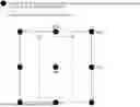


Sources:
- United States Patent and Trademark Office - verify current appl. status at the USPTO↗
Similar patent applications:
- » 20190040511
High-strength galvanized steel sheet, high-strength member, and method for producing high-strength galvanized steel sheet - » 20260071306
HIGH STRENGTH STEEL SHEET, METHOD FOR PRODUCING SAME, MEMBER, AND METHOD FOR PRODUCING SAME - » 20240287637
HIGH STRENGTH STEEL SHEET, HIGH STRENGTH COATED OR PLATED STEEL SHEET, METHODS OF PRODUCING SAME, AND MEMBER - » 20240360532
HIGH STRENGTH STEEL SHEET, HIGH STRENGTH COATED OR PLATED STEEL SHEET, METHODS OF PRODUCING THESE, AND MEMBER - » 20240376577
HIGH STRENGTH STEEL SHEET, HIGH STRENGTH COATED OR PLATED STEEL SHEET, METHODS OF PRODUCING THESE, AND MEMBER - » 20110008648
High-strength steel sheet, strength member for vehicles using the same, and method for producing strength member for vehicles - » 20150027600
Si-containing high strength cold rolled steel sheet, method of producing the same, and automotive members
Recent applications in this class:
- » 20260110067 2026-04-23
ZINC-BASED PLATED STEEL SHEET HAVING EXCELLENT ROOM TEMPERATURE AGING RESISTANCE AND BAKE HARDENABILITY, AND METHOD FOR PRODUCING SAME - » 20260110066 2026-04-23
CLAD STEEL PLATE AND METHOD OF PRODUCING SAME - » 20260110065 2026-04-23
STEEL MATERIAL FOR HIGH-STRENGTH LINE PIPE WITH HIGH FRACTURE TOUGHNESS IN HYDROGEN AND METHOD FOR PRODUCING THE SAME, AND STEEL PIPE FOR HIGH-STRENGTH LINE PIPE AND METHOD FOR PRODUCING THE SAME - » 20260103784 2026-04-16
HOT ROLLED STEEL SHEET - » 20260098328 2026-04-09
DOUBLE ANNEALED ZINC-COATED PRESS-HARDENABLE STEELS - » 20260098327 2026-04-09
COATED ULTRAHIGH-STRENGTH STEEL WITH LOW SPOT WELDING CRACK SENSITIVITY AND MANUFACTURING METHOD THEREFOR - » 20260085391 2026-03-26
HOT ROLLED STEEL SHEET - » 20260071306 2026-03-12
HIGH STRENGTH STEEL SHEET, METHOD FOR PRODUCING SAME, MEMBER, AND METHOD FOR PRODUCING SAME - » 20260055491 2026-02-26
DUAL-PHASE STEEL AND MANUFACTURING METHOD THEREFOR - » 20260049382 2026-02-19
STEEL SHEET
Recent applications for this Assignee:
- » 20260110066 2026-04-23
CLAD STEEL PLATE AND METHOD OF PRODUCING SAME - » 20260103782 2026-04-16
NON-ORIENTED ELECTRICAL STEEL SHEET AND METHOD FOR PRODUCING THE SAME - » 20260103780 2026-04-16
HOT PRESSED MEMBER AND STEEL SHEET FOR HOT PRESS FORMING - » 20260103771 2026-04-16
NON-ORIENTED ELECTRICAL STEEL SHEET, METHOD FOR PRODUCING THE SAME, AND MOTOR CORE - » 20260102819 2026-04-16
IRON-BASED SOFT MAGNETIC COMPOSITE POWDER FOR A DUST CORE, AND METHOD OF PRODUCING SAME - » 20260102801 2026-04-16
COLD ROLLING METHOD, METHOD OF PRODUCING STEEL SHEET, COLD ROLLING LINE, AND STEEL SHEET PRODUCTION LINE - » 20260092338 2026-04-02
HIGH-STRENGTH NON-ORIENTED ELECTRICAL STEEL SHEET AND METHOD FOR PRODUCING SAME - » 20260085376 2026-03-26
METHOD OF PRODUCING IRON ORE PELLETS - » 20260085372 2026-03-26
METHOD FOR PRODUCING GRAIN-ORIENTED ELECTRICAL STEEL SHEET, AND INDUCTION HEATING DEVICE - » 20260084317 2026-03-26
CONVEX PORTION GRINDING SYSTEM, CONVEX PORTION GRINDING METHOD, AND METHOD OF PRODUCING STEEL PRODUCT