IRRIGATOR WHEEL TRACK RUT REPAIR PATCH
US20260103853A1
2026-04-16
19/354,528
2025-10-09
Smart Summary: An irrigator wheel rut repair patch is designed to fix ruts made by irrigation wheels. It consists of recycled crushed concrete or lava rock packed inside a rectangular plastic bag. The bag has small holes that let air out but keep the material inside. This patch can be placed directly into the rut, creating a smooth path for the wheel to travel over. It helps maintain the functionality of the irrigation system by ensuring the wheels can move easily across the repaired area. 🚀 TL;DR
Abstract:
An irrigator wheel rut repair patch comprises a first aggregate consisting of one of recycled crushed concrete and lava rock, and a plastic bag filled with the first aggregate. The plastic bag comprises a rectangular shape with a first side and a second side which is opposite the first side. At least one of the first side and the second side is pre-punctured with openings which facilitate detrainment of air from within the plastic bag while prohibiting aggregate from escaping the plastic bag through the pre-punctured openings. The rut repair patch is configured to be emplaced whole within a rut of an irrigator wheel track such that a path of a wheel of the irrigator is bridged from a first functional portion of the wheel track, across the rut via the rut repair patch, to a second functional portion of the wheel track.
Assignee:
- Traction Rock Products LLC 1 🇺🇸 Aurora, NE, United States
Applicant:
Interested in similar patents?
Get notified when new applications in this technology area are published.
Classification:
E01C11/005 » CPC main
Details of pavings Methods or materials for repairing pavings
E01C11/00 IPC
Details of pavings
Description
CROSS-REFERENCE TO RELATED APPLICATIONS
This application claims priority to and benefit of U.S. Provisional Application 63/705,781 titled CENTER PIVOT IRRIGATION RUT REPAIR PATCH, filed October 10, 2024, which is hereby incorporated by reference in its entirety.
BACKGROUND
Center pivot irrigator systems are widely utilized in agricultural operations to efficiently irrigate large areas of cropland. These systems typically consist of a fixed central tower from which a long irrigation pipe extends radially outward, supported by a series of mobile towers that move in circular or arc-shaped paths around the central point. Each mobile tower is equipped with wheels that enable movement across the field while carrying the irrigation infrastructure.
As these irrigation systems operate, the mobile towers repeatedly traverse the same circular/arced paths, with their wheels making continuous contact with the soil such that eventually irrigator wheel tracks (sometimes referred to as “pivot tracks”) are worn into the soil of a farm field. The combination of the substantial weight of the irrigation equipment and the presence of water from the irrigation process creates conditions where the soil becomes saturated and loses its structural integrity. Over time, this repeated passage of heavy equipment over wet soil may lead to the formation of non-functional portions (sometimes referred to as “ruts”) in the wheel tracks.
The development of wheel track ruts presents several challenges for agricultural operations. Deep ruts can cause irrigation towers to become stuck or immobilized, leading to equipment damage, operational delays, lost productivity due, shortfalls in irrigation, and/or damage to crops.
BRIEF DESCRIPTION OF FIGURES
The accompanying figures, which are incorporated in and form a part of the Description of Embodiments, illustrate various embodiments of the subject matter and, together with the Description of Embodiments, serve to explain principles of the subject matter discussed below. Unless specifically noted, the figures referred to in this Brief Description of Figures should be understood as not being drawn to scale. Non-limiting and non-exhaustive examples are described with reference to the following figures, in which like items are labeled with like item numbers.
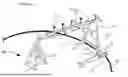
FIG. 1 illustrates a center pivot irrigator system with a plurality of moving towers, wheels of the moving towers, and tracks made by the wheels, in accordance with various embodiments.
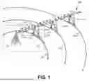
FIGS. 2A and 2B illustrate the obverse and reverse sides of an empty plastic bag which may be used as a component of a rut repair patch, in accordance with various embodiments.
FIG. 3 illustrates aggregate pieces disposed in a plastic bag to form a rut repair patch, in accordance with various embodiments.
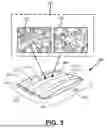
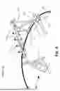
FIG. 4 illustrates an enlarged detail of the center pivot irrigator system of FIG. 1 with the rut repair patch deployed in a wheel track rut, in accordance with various embodiments.
FIG. 5 illustrates a flow diagram of an example method of provisioning a rut repair patch, in accordance with various embodiments.
FIG. 6 illustrates a flow diagram of an example method of repairing a rut in an irrigator wheel track, in accordance with various embodiments.
DESCRIPTION OF EMBODIMENTS
Reference will now be made in detail to various embodiments of the subject matter, examples of which are illustrated in the accompanying drawings. While various embodiments are discussed herein, it will be understood that they are not intended to limit to these embodiments. On the contrary, the presented embodiments are intended to cover alternatives, modifications, and equivalents, which may be included within the spirit and scope of the various embodiments described herein and as defined by the appended claims. Furthermore, in this Description of Embodiments, numerous specific details are set forth in order to provide a thorough understanding of embodiments of the present subject matter. However, embodiments may be practiced without these specific details. In other instances, well-known methods, procedures, and components have not been described in detail as not to unnecessarily obscure aspects of the described embodiments.
Overview of Discussion
Center pivot irrigator systems are widely utilized in agricultural environments to efficiently irrigate large, often circular, areas of cropland. These systems typically extend substantial distances from a central fixed location, with some installations reaching over one thousand feet in length from the center point to the distal end. The operational design of center pivot irrigator systems (also referred to as “center pivot irrigators” or “central pivot irrigators”) involves irrigation pipes and spray nozzles suspended between a central fixed location and multiple towers that roll on wheels in circular or arc-shaped paths around the central fixed location.
During operation, the wheels of each tower make continual contact with the cropland as the towers travel in their circular/arced paths around the fixed center. This repeated contact compacts the soil in the transited crop land, creating a set of concentric circular/arced paths along which the wheels repeatedly roll. Such wheel tracks made by center pivot irrigators are commonly called “pivot tracks.” The combination of repeated rolling along the same pivot track and the presence of ample water supplied by the irrigator system often results in the development of non-functional (e.g., impassible or precarious to transit) portions in the pivot tracks made by the wheels of the center pivot irrigator system. A non-functional portion may be referred to as a “rut” (and may also referred to herein as an “irrigator wheel track rut” or a “pivot track rut” or a “wheel rut” or a “wheel track rut” or a “rutted portions of a wheel track” or the like). A non-functional portion or “rut” may manifest as a low spot, muddy area, and/or rough terrain in the pivot track made by the wheels of a moving tower.
The development of rutted portions in the wheel tracks/pivot tracks can render these areas non-functional. When wheels encounter these rutted portions, the wheels may become stuck in place due to mud accumulation or may be unable to proceed through the rutted portion due to high-centering of the axles that support the wheels, and/or may damage portions of the irrigator system when transit is attempted. Such conditions can halt the operation of the irrigator system and require intervention to restore functionality. A further complication is the need to quickly repair a rutted wheel track which is typically located in the midst of a field of growing crops, but to effect the repair without trampling or destroying the growing crops.
The present disclosure addresses these operational challenges through a rut repair patch system designed for center pivot irrigation applications. The rut repair patch provides a portable solution that can be rapidly deployed with little to no damage to growing crops. Once deployed the rut repair patch bridges non-functional portions of wheel tracks, allowing wheels to traverse from a functional portion of the track, across a rutted and non-functional portion via the patch, and continue to an adjacent functional portion of the track. A rut repair patch can be hand-carried by an able-bodied adult human, and several may be stacked on a small vehicle, such as a 4-wheeled ATV (i.e., a “four-wheeler”) which is small enough that it may be driven along a pivot wheel track of a center pivot irrigator without damaging or trampling growing crops. The rut repair patch incorporates an aggregate material or a combination of aggregate materials contained within a specially configured plastic bag that facilitates simplified deployment in the irrigation environment. Once deployed, the rut repair patch is adapted to be left in place in the field, in-bag. In some embodiments, the plastic bag which contains the aggregate material is configured to biodegrade into the soil of the field over a period of time which may be predetermined (within a range) based on the chemical composure of the plastic from which the bag is made.
Center Pivot Irrigator System
FIG. 1 illustrates a center pivot irrigator system 100 with a plurality of moving towers 110 (110-1, 110-2, 110-3, etc.), wheels 112 of the moving towers 110, and tracks 130 (130-1, 130-2, 130-3, etc.) made by the wheels 112, in accordance with various embodiments. A dashed box indicates a portion of FIG. 1 (detail area 175) which is shown in greater detail in FIG. 4. As illustrated, the center pivot irrigator system 100 comprises a fixed central tower 105 positioned at a central point about which the entire central pivot irrigator system 100 operates. The system 100 includes irrigation pipes 115 that extend outwardly from the fixed central tower 105 and are supported by a sequence of moving towers 110 arranged in a linear configuration extending radially from the fixed central tower 105. Each moving tower 110 includes wheels 112 (e.g., 112-1, 112-2 on tower 110-1) that enable the moving towers 110 to travel along the cropland ground surface 101 (e.g., the cropland soil in a farm field). The width of the wheels 112 (i.e., the width at a point where a wheel 112 contacts ground 101) is typically between 10-15 inches. The moving towers 110 are mechanically connected to maintain their relative positions as the system 100 rotates around the fixed central tower 105. A plurality of sprinkler heads 117 and/or sprinkler drops (not depicted) are coupled with the supported irrigation pipes 115 at intervals along the length of the system 100, providing water distribution across the cropland surface 101 beneath and adjacent to the center pivot irrigator system 100.
The operational mechanics of the center pivot irrigator system 100 involve the coordinated movement of the moving towers 110 in circular or arc-shaped paths around the fixed central tower 105. As the center pivot irrigator system 100 operates, each moving tower 110 travels along its designated circular/arced path, with the wheels 112 of each moving tower 110 making continuous contact with the cropland ground surface 101. The wheels 112 of each moving tower 110 follow the same circular/arced track repeatedly during each irrigation cycle, creating distinct wheel embedded irrigator wheel tracks 130 (e.g., 130-1, 130-2, 130-3), often called “pivot tracks,” in the ground 101 over time.
As shown in FIG. 1, the irrigation wheel track/pivot track 130-1 created by moving tower 110-1 of the center pivot irrigator system 100 includes both functional portions 121, 123 and non-functional portions 122. The functional portions 121, 123 of irrigation wheel track 130-1 provide stable surfaces that allow the wheels 112-1, 112-2 to travel without impediment, maintaining the proper operation of the center pivot irrigator system 100. However, as can be seen, certain sections of the wheel track 130-1 may develop into non-functional portions 122, referred to herein as “ruts,” due to the combination of repeated wheel traffic and water saturation, and/or other factors.
The formation of a non-functional portion/rut 122 in irrigator wheel track 130-1 presents operational challenges for the center pivot irrigator system 100. When wheels 112-1, 112-2 of moving tower 110-1 encounter rutted portion 122, several problematic conditions may arise that impede the continued movement of the system 100. In some cases, the wheels 112-1 and/or 112-2 may become stuck in accumulated mud and/or impassable terrain within the rutted portions, preventing forward progress of the affected moving tower 110-1. Additionally, the depth of rut 122 may cause an axle 114 supporting the wheels 112 of a tower 110-1 to contact the ground surface 101, a condition known as high-centering, which may also prevent the wheels 112 of moving tower 110-1 from maintaining traction and continuing along their intended path. In some situations, transiting or attempting to transit such a non-functional portion may damage a component of the irrigator 100 such as a wheel 112 or a gear box. These conditions can halt the operation of the center pivot irrigator system 100 and/or damage it, disrupting the irrigation schedule and potentially affecting crop health if the system 100 cannot complete its programmed/scheduled irrigation cycles.
Rut Repair Patch Components and Construction
FIGS. 2A and 2B illustrate the obverse and reverse sides of an empty plastic bag 200 which may be used as a component of a rut repair patch, in accordance with various embodiments. The plastic bag 200 illustrated in FIGS. 2A and 2B is open (unsealed) on the upper horizontal edge and sealed on the lower horizontal edge. As depicted in FIG. 2A, the plastic bag 200 exhibits a rectangular configuration with specific dimensional parameters that facilitate handling and deployment by agricultural personnel. In some embodiments, the length dimension 206 of plastic bag 200 measures between 24 and 36 inches, while the width dimension 207 ranges between 10 and 20 inches. In some embodiments, the length dimension 206 of plastic bag 200 measures between 28 and 31 inches, while the width dimension 207 ranges between 14 and 16 inches. These dimensional specifications provide sufficient coverage area to bridge rutted portions of wheel tracks while maintaining a size that remains manageable for manual transport and positioning by most able-bodied adult humans. In one example, a plastic bag 200 may be approximately 25 inches long by 15 inches wide and may be configured to hold approximately 0.5 cubic feet of aggregate. In one example, a plastic bag 200 may be approximately 29.5 inches long by 19.5 inches wide and may be configured to hold approximately 1.0 cubic feet of aggregate. In one example, a plastic bag 200 may be approximately 29.5 inches long by 15 inches wide and may be configured to hold approximately 0.75 cubic feet of aggregate.
In some embodiments, the plastic bag 200 has pre-punctured openings 210 (e.g., 210-1, 210-2), such as a plurality of small circular openings, small oval shaped openings, small crescent shaped openings, small slits or the like which allow air to escape the plastic bag 200 and water/mud to enter the plastic bag 200 when it is used to patch a rut. The pre-punctured openings 210 are small enough (e.g., 1/32 – 1/8 inch across) that aggregate disposed within bag 200 cannot easily escape through them. The pre-punctured openings 210 may be on one planar surface/side of the plastic bag 200 (e.g., side 208, as shown in FIG. 2A) or both planar surfaces/sides (e.g., the obverse side 208 and the reverse side 209 (shown in FIG. 2B)).
The plastic bag 200 may be sized to contain between 0.5 and 1.5 cubic feet of aggregate material, providing sufficient mass and volume to effectively bridge non-functional portions of wheel tracks/pivot tracks 130. In some embodiments, the average cubic feet contained by a plastic bag 200 is 0.75 cubic feet but may vary in the range between 0.7 and 0.8 cubic feet depending, for example, on the accuracy of measurement during filling. The weight of a plastic bag 200 containing about 0.75 cubic feet of aggregate may vary between 25-75 pounds depending on the aggregate/mixture of aggregates used to fill the plastic bag 200 and the accuracy of the filling.
The material composition of the plastic bag 200 may vary depending on the intended service life and environmental conditions. In some cases, the plastic bag 200 may be constructed from non-biodegradable plastic material that maintains structural integrity over extended periods without breaking down over time.
Alternatively, the plastic bag 200 may be configured to biodegrade within a preselected time period upon exposure to environmental factors including sun, soil, and water. The period of time may be a range. The range may be between 6 months and 10 years in some embodiments, or between 6 months and 5 years in some embodiments. Other ranges are possible and anticipated. The biodegradable configuration allows the plastic bag 200 to eventually decompose while the contained aggregate materials remain in place to continue providing track stabilization.
In some embodiments biodegradable embodiments, the plastic bag 200 may be made from polylactic acid (PLA), which is derived from renewable plant materials such as corn starch, sugarcane, or cassava roots. PLA exhibits good structural integrity during use, before biodegrading. In some cases, the plastic bag 200 may be formed from polyhydroxyalkanoates (PHAs), which are naturally occurring biopolymers produced by bacterial fermentation of organic materials. PHAs provide excellent durability and flexibility while maintaining biodegradable characteristics suitable for agricultural applications. The plastic bag 200 may alternatively be constructed from starch-based biodegradable plastics, which combine natural starch with biodegradable synthetic polymers to create materials that break down through microbial action in soil environments. In some aspects, the plastic bag 200 may be made from polybutylene succinate (PBS) or polybutylene adipate terephthalate (PBAT), which are biodegradable polyesters that maintain structural integrity under load while decomposing when exposed to soil microorganisms. The plastic bag 200 may also be formed from cellulose-based biodegradable films, which are derived from plant cellulose and modified to provide the necessary strength and water resistance for containing aggregate materials. In some embodiments, the plastic bag 200 may incorporate biodegradable additives mixed with conventional plastic materials to accelerate decomposition. These additives may include enzymes, catalysts, or organic compounds that promote breakdown of the plastic structure when exposed to environmental conditions. In some embodiments, the plastic bag 200 is made from a polyolefin plastic which includes an additive (e.g., 1% additive), that breaks down carbon-to-carbon bonds in polymer molecules. In some embodiments such a bag may biodegrade within 6 months to 42 months by enabling microorganisms to consume the carbon-to-carbon bonds as a fuels source and bio-assimilate the plastic bag 200. The breakdown time range may be generally selected or predetermined by adjusting the amount of the additive. The term “generally selected,” is used because environmental conditions which support biodegradation can vary widely. The SPTek ECLIPSETM additive from Smart Plastic Technologies, LLC of Northbrook, Illinois and Knoxville, TN, is one example of an additive that may be included in a polyolefin plastic to cause the plastic to biodegrade within a generally selectable predetermined range of time.
As further shown in FIG. 2A, the plastic bag 200 may incorporate reinforcement features to enhance durability during handling, transport, and deployment. For example, in some embodiments, reinforcement strips 211 (e.g., 211-1, 211-2) may be embedded within the plastic material of the plastic bag 200 to provide additional tensile strength and resistance to tearing. In some such embodiments, plastic bag 200 may include composite reinforcing materials (i.e., one or more reinforcement strips 211) that comprise: reinforced areas of biodegradable polymers; include natural fibers such as hemp, flax, or jute; or combine biodegradable polymers with such natural fibers. Such use of reinforcement strips 211 or other reinforcements enhances strength and durability while maintaining biodegradable properties. For example, the depicted reinforcement strips 211 distribute stress loads across the plastic bag 200, reducing the likelihood of failure during transport, handling, and/or emplacement when the plastic bag 200 contains heavy and/or irregularly shaped aggregate materials.
In some embodiments, the plastic bag 200 may incorporate one or more handles 220 (220-1, 220-2) to facilitate lifting and positioning of the plastic bag 200. The handle(s), when included, may also be made of biodegradable polymer, natural fibers, or a combination thereof. In some embodiments, the handle(s) may be made of the same material as plastic bag 200. One or more handles 220 (e.g., handle 220-1) may be included on one end of plastic bag 200 in some embodiments. In other embodiments, handles 220 (e.g., handle 220-1 and handle 220-2) may be included on opposing ends of plastic bag 200 from one another.
FIG. 2B illustrates the reverse side 209 of plastic bag 200 according to various embodiments. In some embodiments, the reverse side 209 is a mirror images of the obverse side 208. In other embodiments, the reverse side 209 may omit one or more features that is/are included on the obverse side 208. In one embodiment, the obverse side 208 of plastic bag 200 may include one or more pre-punctured openings 210 (e.g., 210-3, 210-4) while the reverse side 209 does not. In one embodiment, the obverse side 208 of plastic bag 200 may include one or more reinforcement strips 211 (e.g., 211-3, 211-4) while the reverse side 209 does not.
FIG. 3 illustrates aggregate pieces disposed in a plastic bag 200 to form a rut repair patch 300, in accordance with various embodiments. The rut repair patch 300 (also referred to as a “irrigator wheel track rut repair patch,” a “rut patch” or a “patch”) comprises a plastic bag 200 filled with aggregate material(s) selected for their performance and other characteristics. In some embodiments, the aggregate material may be one or some combination of, a first aggregate and a second aggregate. In one embodiment, the first aggregate is one of recycled crushed concrete 320 and lava rock 330; while the second aggregate is the other of the recycled crushed concrete 320 and the lava rock 330. The single use or the combination of these aggregates within the plastic bag 200 creates a portable repair solution (i.e., rut patch 300) that addresses the operational challenges presented by rutted irrigator wheel tracks. Once filled with aggregate material and sealed, a flat stored (i.e., lying flat on a flat surface) rut repair patch 300 has a thickness of between 4 inches and 8 inches in some embodiments. More particularly, the objective lay-flat-thickness of a plastic bag 200 filled with 0.75 cubic feet of aggregate may be 6 inches with some variation in thickness (e.g., between about 5 inches and about 7 inches), in some embodiments.
The recycled crushed concrete 320 which is utilized, in some embodiments, typically exhibits an average piece length between 1.0 inches and 3.5 inches, with this size range being consistent with recycled crushed concrete aggregate that has been screened to grade 2 or grade 2+ specifications. In grade 2+ applications, the concrete pieces average between 2.5 and 3 inches in length, providing excellent load distribution characteristics for irrigator wheel track rut repair applications. In some embodiments, other sizes, grades may be utilized. The recycled crushed concrete 320 originates from the breakdown of original concrete structures, including building slabs, curbs, foundations, roads, and sidewalks, through the use of industrial crushing equipment and hammer mills. During processing, the concrete pieces undergo screening to remove dirt and other particles, and the resulting material may be separated by aggregate size to produce different grades suitable for various applications.
The lava rock 330 which is utilized typically exhibits an average piece length between 0.5 inches and 2 inches, with this size being consistent with crushed aggregate grade 3 specifications. In some embodiments, other sizes/grades may be utilized. The lava rock 330 size approximates that of decorative lava rock available at lawn and garden stores for landscaping applications. The porous nature of lava rock 330 results in a lower density compared to solid aggregate materials, reducing the overall weight of the rut repair patch 300 while maintaining structural integrity. In some cases, the second aggregate may comprise alternative materials such as white rock, pumice stone, or gravel instead of lava rock 330, providing flexibility in material selection based on regional availability and cost considerations.
The ratio of the first aggregate and second aggregate within a mixture 350 in the plastic bag 200 may vary across a wide range of proportions while maintaining the functional characteristics of the rut repair patch 300. The mixture 350 may include ratios ranging from 100% first aggregate with 0% second aggregate to configurations with higher proportions of second aggregate, such as 1% first aggregate with 99% second aggregate. Intermediate ratios may include combinations such as: 90-98% first aggregate with 2-10% second aggregate; 80-89% first aggregate with 11-20% second aggregate; 70-79% first aggregate with 21-30% second aggregate; 60-69% first aggregate with 31-40% second aggregate; 50-59% first aggregate with 41-50% second aggregate; 50% first aggregate and 50% second aggregate; 40-49% first aggregate with 51-60% second aggregate; 30-39% first aggregate with 61-70% second aggregate; 20-29% first aggregate with 71-80% second aggregate; 10-19% first aggregate with 81-90% second aggregate; and 2-10% first aggregate with 90-98% second aggregate. Any of these ratios are approximate within the measuring margins of error of equipment used to measure, weight, and fill the aggregate(s) into a plastic bag 200.
It should be appreciated that for equivalent size pieces, lava rock is much lighter than recycled crushed concrete (a volume of lava rock weighs half or less than an equivalent recycled crushed concrete); while recycled crushed concrete has stronger load bearing properties; breaks down under wheel traffic more slowly than lava rock, and may be half the cost of lava rock 330 in areas where lava rock isn’t natively quarried. Accordingly, the ratio of recycled crushed concrete to lava rock in an aggregate mixture may be selected and adjusted based on one or more of a variety of factors, including but not limited to: availability of the aggregates; desired structural properties of the rut repair patch 300; desired weight of a filled rut patch 300 (recycled crushed concrete is heavier than lava rock); cost of available aggregates (which may vary based on location); and cost of transportation of aggregates. For example, a 50/50 mixture 350 of recycled crushed concrete 320 and lava rock 330 results in a rut repair patch that is at once economical (due to the low cost and ready availability in most locales of recycled crushed concrete), strong due to the use of the recycled crushed concrete, and lighter than a bag of 100% recycled crushed concrete due to a volume of lava rock being far lighter than an equivalent volume of recycled crushed concrete. Similarly, an approximately 75/25 mixture 350 of lava rock 330 to recycled crushed concrete 320 results in a rut repair patch that may be more economical than 100% lava rock (due to the low cost and ready availability in most locales of recycled crushed concrete that is the mixture), structurally stronger and longer lasting due to the use of some recycled crushed concrete instead of just 00% lava rock, and lighter than a bag of 100% recycled crushed concrete. Such a 75/25 mixture would typically result in a 0.75 cubic foot rut repair patch 300 weighing between 30 and 40 pounds (where lava rock weighs around 36 pounds per cubic foot and recycled crushed concrete weights about 75 pounds per cubic foot). In some embodiments, a mix of aggregates 350 may be selected to target a filled bag 200 weighing between 28 and 35 pounds for approximately 0.7-0.8 cubic feet of aggregate mixture 350, a weight range at which most able-bodied humans can carry, handle, and/or emplace a rut patch 300.
In some cases, the plastic bag 200 may contain only the first aggregate without any second aggregate admixed with the crushed concrete 320, resulting in a configuration of 100% first aggregate and 0% second aggregate. In some cases, the plastic bag 200 may contain only the second aggregate without any first aggregate admixed with the lava rock 330, resulting in a configuration of 100% second aggregate and 0% first aggregate.
In some embodiments, one or more other aggregates (other than recycled crushed concrete and lava rock) may be added to a mixture of aggregates or substituted for aggregate 320 and/or aggregate 330. Some non-limiting examples of additional aggregates included white rock (e.g., limestone rock, travertine rock, or the like), pumice stone, and gravel. For example, in some such embodiments, a plastic bag 200 may be filled with a mixture of recycled crushed concrete 320, lava rock 330, and white rock. Similarly, in some such embodiments, a plastic bag 200 may be filled with a mixture of lava rock 330 and white rock.
Deployment and Operation of a Rut Repair Patch
FIG. 4 illustrates an enlarged detail view 175 of the center pivot irrigator system 100 of FIG. 1 with rut repair patch 300-1 and 300-2 deployed in a wheel track rut 122, in accordance with various embodiments. With continued reference to FIG. 4, the deployment process for a rut repair patch 300 involves positioning a patch 300 (i.e., patch 300-1 and or 300-2) directly within the non-functional portion 122 of the wheel track 130-1. Conveniently, this may be accomplished without opening or modifying the plastic bag 200 structure of a rut repair patch 300 (i.e., it does not need to be opened, cut, or emptied). This is because a rut repair patch 300 is configured to be placed as a complete unit, maintaining the integrity of the plastic bag 200 and the aggregate materials contained therein throughout the deployment process. The rectangular pillow shape of the filled plastic bag 200 conforms to the contours of the rutted portion while providing sufficient structural support to accommodate the weight, movement, and ground contact width of wheels 112. The rut repair patch 300 functions as a structural bridge that spans the non-functional portion 122 of the wheel track 130-1, creating a stable pathway for wheel passage.
As can be seen, the deployment of one or more rut repair patches 300 addresses the operational challenges presented by non-functional portions of wheel tracks (i.e., rutted portions) 122. The rut repair patches 300-1 and 300-2 provide a bridging solution that enables wheels 112-1 and 112-2 to traverse from a first functional portion 121 of the wheel track 130-1, across a non-functional portion/rut 122 ,and continue to a second functional portion 123 of the wheel track 130-1 on the opposite side of the rutted area. The strategic placement of the rut repair patches 300-1 and 300-2 restores continuity to the wheel track 130-1, allowing the center pivot irrigator system 100 to resume normal operation, rolling along its pivot tracks 130, without interruption from the rutted conditions in irrigator wheel track 130-1.
The operational characteristics of the rut repair patch 300 accommodate the repeated passage of irrigator wheels 112 during multiple irrigation cycles. The aggregate materials within the plastic bag 200 may gradually break down into smaller pieces through the repeated loading and unloading cycles imposed by wheel traffic, eventually reaching a near-powdery state that integrates with the surrounding soil. In cases where the plastic bag 200 incorporates biodegradable materials, the structure of plastic bag 200 may decompose over the predetermined time period while the aggregate materials remain in place to continue providing track stabilization. Thus, once placed, the rut repair patch 300 may remain in position within the non-functional portion 122 indefinitely, or until the plastic bag 200 biodegrades and/or aggregate materials disintegrate.
With continued reference to FIG. 4, as previously described, wheels 112 on center pivot irrigators such as center pivot irrigator system 100 are typically in the range of 10 to 15 inches in width. Thus, the shape of the rut patch 300 and its particularly selected length and width dimensions facilitate convenient placement across a rut in a manner that provides traction and stability to bridge the full width of wheel 112-1 from a first functional portion 121 of track 130-1 which is adjacent to a first side of a rut 122, across the non-functional portion (e.g., rut 122), and to a second functional portion 123 of the track 130-1 which is adjacent to the rut 122 but on a second and opposite side of the rut 122 from the first functional portion 121. For example, a plastic bag 200 that is 30 inches long and 16 inches wide may be placed with its 30-inch side perpendicular to the direction of travel of the wheels 112, such that it spans the full width of the ground contact area of a 10 to 15-inch-wide irrigator wheel 112 (e.g., wheel 112-1) with some margin on each side. Alternatively, the same plastic bag 200 may be placed with its 16-inch side perpendicular to the direction of travel of the wheels 112, such that it still spans the full width of the ground contact area of a 10 to 15 inch-wide irrigator wheel 112 (e.g., wheel 112-1), but with less margin on each side. In this manner, in some embodiments, the length and width dimensions of a plastic bag 200 are particularly chosen so that one or both of the length and width dimensions are larger than the average width range of irrigator wheels 112 so that a single patch 300 can span the contact area of a wheel 112.
When patching a rut, the rut patch 300 is placed in the rut (i.e., non-functional portion 122 of track 130), as a full and sealed plastic bag 200, without opening the plastic bag 200, and the patch 300 remains in the rut in perpetuity, or else until the aggregate inside the rut patch disintegrates and/or until, in some embodiments, the plastic bag 200 biodegrades. Over a long period of time, typically measured in years, recycled crushed concrete 320 aggregate and lava rock 330 aggregate disintegrate into smaller pieces and even into a near powdery state after being repeatedly driven over by a wheel 112 of a moving pivot tower 110.
When the rut patch 300 is placed within a rut (i.e., non-functional portion 122 of track 130), water and/or mud within the rut (when present) entrain/enter into the plastic bag 200 through one or both sides of the bag which via the pre-punctured openings 210 which facilitate detrainment/exit of air from within the plastic bag 200 while also being small enough for prohibiting aggregate from escaping the bag through the pre-punctured openings 210. In this manner, the pre-punctured openings 210 facilitate the rut patch settling into the rut, rather than floating upon water or mud which is in the rut as would happen with a sealed bag. Additionally, by being pre-punctured, a human is not required to slice the plastic bag of the rut patch, thus preventing the wielding and use/loss of a knife or sharp tool in a very muddy and precarious environment where the human emplacing the rut patch 300 may be hip deep in mud.
With continued reference to FIG. 4, the deployment strategy for the rut repair patch 300 may involve the use of a single rut repair patch 300 (e.g., patch 300-1) to repair a small rut or of multiple rut repair patches 300 to address larger rutted portions or extended sections of non-functional track. For example, as shown in FIG. 4, a plurality of rut repair patches 300 (300-1, 300-2) may be utilized to patch and bridge extensive rutted portions, with configurations ranging from two rut patches 300 for moderately rutted portions to more rut patches 300 (e.g., 3, 5, 10, 20, etc.) for larger ruts, with the number of rut repair patches 300 used for a repair depending on the size and extent of the rutted portion requiring repair. Accordingly, multiple rut patches 300 may be positioned in overlapping or adjacent configurations to provide continuous coverage across the entire length of the non-functional portion 122. The modular nature of the rut repair patch 300 allows for flexible deployment strategies that can accommodate varying rut sizes and configurations encountered in different agricultural environments and soil conditions. Additionally, the use of multiple rut patches 300 provides redundancy in the repair.
Method of Provisioning a Rut Repair Patch
FIG. 5 illustrates a flow diagram 500 of an example method of provisioning a rut repair patch 300, in accordance with various embodiments.
At 510 of flow diagram 500, in some embodiments, a plastic bag 200 is provided into which an aggregate (320, 330) or mixture 350 of aggregates may be disposed. For example, the plastic bag 200 may be provided by a manufacturer of bags, a seller of bags, or an entity which fills the bags with an aggregate (320, 330) or mixture 350 of aggregates. In some embodiments, the plastic bag 200 includes one or more features such as one or more pre-punctured openings 210, reinforcements, and/or one or more handles 220. The plastic bag 200 may be biodegradable, as has previously been described herein. The time over which a plastic bag biodegrades, by be predetermined over a generally selectable range based upon its material composition and construction (the predetermined time is an objective because environmental conditions which support biodegradation can vary widely). The range of time may predetermined, for example, to be between about 6 months and about 5 years in some embodiments in order to provide enough durability for shipping, storage, and initial emplacement in a rut.
At 520 of flow diagram 500, in some embodiments, the plastic bag 200 is filled with an aggregate to form a rut repair patch 300. In some embodiments, the aggregate is one or more of lava rock 330 aggregate and recycled crushed concrete 320 aggregate. In some embodiments, this comprises filling plastic bag 200 with a mixture 350 of lava rock 330 aggregate and recycled crushed concrete 320 aggregate. In some embodiments, this comprises filling plastic bag 200 with only lava rock 330 aggregate or only recycled crushed concrete 320 aggregate. As previously described, in some embodiments, additional and/or alternative aggregates may be utilized in a rut repair patch 300. In some embodiments, the rut repair patch 300 may have a length 206 of between 28 and 31 inches, a width 207 of between 14 and 16 inches, a filled lay-flat thickness 305 of between 5 and 7 inches, and contain between 0.7 and 0.8 cubic feet of aggregate 350.
At 530 of flow diagram 500, in some embodiments, the rut repair patch 300 is provided for us in repairing a rut in a wheel track 130 of an irrigator wheel (such as irrigator wheel 112-1). This may comprise one or more of shipping the rut repair patch 300 to a user or to a point of sale, offering the rut patch 300 for sale, and/or advertising the rut repair patch 300 for repairing irrigator wheel track ruts.
Method of Repairing a Rut in an Irrigator Wheel Track
FIG. 6 illustrates a flow diagram 600 of an example method of repairing a rut in an irrigator wheel track, in accordance with various embodiments.
At 610 of flow diagram 600, in some embodiments, a rut repair patch 300 is provided. The “providing” may involve offering the rut repair patch 300 for sale at a point of sale and/or transporting the rut repair patch 300 into an agricultural field to a location proximate to the rut being repaired. In various embodiments, the rut repair patch 300 comprises at least a first aggregate contained within a biodegradable plastic bag 200 having one or more pre-punctured openings 210 on one or more surfaces of the biodegradable plastic bag 200. The first aggregate consists of one of recycled crushed concrete 320 and lava rock 330. In some embodiments, when the first aggregate is recycled crushed concreate the average length of pieces of the first aggregate is between 0.5 inches and 3.5 inches (e.g., grade 2 and/or grade 2+). Other sizes/grades of recycled crushed concreate may be used, in some embodiments.. In some embodiments, when the first aggregate is lava rock 330, the average length of pieces may be between 0.5 inches and 2.0 inches (e.g., grade 3). Other sizes/grades of lava rock may be used in some embodiments. For example, in some embodiments, when the first aggregate is lava rock 330, the average length of pieces may be between 1 inch and 3.5 inches. In some embodiments, the plastic bag 200 may have one or more reinforcements and/or may have one or more handles (as illustrated in FIGS. 2A, 2B, and 3). In some embodiments, the rut repair patch 300 may have a length 206 of between 28 and 31 inches, a width 207 of between 14 and 16 inches, a filled lay-flat thickness 305 of between 5 and 7 inches, and contain between 0.7 and 0.8 cubic feet of aggregate 350.
In some embodiments, the rut repair patch 300 includes a mixture 350 of the first aggregate and a second aggregate, where the second aggregate is the other of lava rock 330 and recycled crushed concrete 320 that is not used as the first aggregate (i.e., lava rock and recycled crushed concrete are mixed together in biodegradable plastic bag 200 to create rut patch 300). The ratios of the first aggregate and second aggregate in the mixture 350 may be selected and/or adjusted depending on a number of factors, as described previously herein. In one embodiment, the mixture includes between 70% and 80% lava rock 330 with the remainder (20%-30%) being recycled crushed concrete 320, which results in a rut patch 300 which is fairly light, has improved structural properties over lava rock alone, and also economically includes available recycled crushed concrete 320 to reduce cost in an area where lava rock 330 is shipped to a manufacturing facility due to not being natively available nearby. Additionally, this use of recycled crush concrete 320 is an environmentally friendly way to reuse, recycle, and/or dispose of previously used concrete.
At 620 of flow diagram 600, in some embodiments, the rut repair patch 300 is placed, as a whole and unopened unit, within the rut (i.e., within a non-functional portion/rut 122 of wheel track 130-1) without opening the plastic bag 200. This may involve a human or a machine (e.g., a front-end loader) placing the rut repair patch 300 in the rut 122.
At 630 of flow diagram 600, in some embodiments, the rut repair patch 300 is left in place such that air in the plastic bag 200 detrains/exits via the pre-punctured opening(s) while water and/or mud within the rut (if present) entrain/enter into the biodegradable plastic bag 200 via the pre-punctured opening(s), thus facilitating settling of the rut repair patch 300 into the rut to effect repair of the rut. With reference to FIG. 4, once emplaced in a rut, one or more rut repair patches bridge a wheel track 130 from a first functional portion of the irrigator wheel track 130 (e.g., functional portion 121 of track 130-1), across the rut (e.g., non-functional portion 122 of track 130-1), to a second functional portion (e.g., functional portion 123 of track 130-1). That is, the path of a wheel 112 utilizes rut repair patch 300 as a bridge between functional portions 121 and 123. The rut repair patch 300 can then be left in place where the biodegradable plastic bag 200 biodegrades over time. The degrading may occur over a predetermined amount of time that is associated with the material used to form the biodegradable plastic bag 200. In a situation where a single rut repair patch 300 is insufficient to repair the rut by bridging the rut between functional portions of the irrigator wheel track, two or more rut repair patches 300 may be employed to effect repair of the rut.
Other Embodiments
The rut repair patch described herein may be utilized, in the same or similar fashion to repair a rut in a wheel track made by rolling irrigators other than a center pivot irrigator system. For example, the rut repair patch can be similarly utilized in the manner described above to repair a rut in the wheel track of a hose reel irrigator system that uses a mobile rain gun; where the rut being repaired may be in a track made by a wheel of the hose reel or by in a track made by a wheel of the mobile rain gun. Likewise, the rut repair patch can be similarly utilized in the manner described above to repair a rut in the wheel track of a side roll irrigator system that uses irrigation pipe as the axels between rolling wheels and typically rolls in more or less a straight line back and forth across a field under irrigation. In either of these or like instantiation, wheeled components of an irrigator system roll repeatedly over the same ground and create a track which can become rutted and non-functional (i.e., prevent a component of the irrigator system from moving through the non-functional portion). One or more rut repair patches 300 may be utilized as described herein to bridge across a non-functional portion of the track (i.e., a rutted portion) which is between two adjacent functional portions of the track.
Conclusion
A number of example implementations have been described. Nevertheless, it will be understood that various modifications may be made without departing from the spirit and scope of the disclosure. Accordingly, other implementations are within the scope of the following claims. The examples set forth herein were presented in order to best explain, to describe particular applications, and to thereby enable those skilled in the art to make and use embodiments of the described examples. However, those skilled in the art will recognize that the foregoing description and examples have been presented for the purposes of illustration and example only. The description as set forth is not intended to be exhaustive or to limit the embodiments to the precise form disclosed. Rather, the specific features and acts described above are disclosed as example forms of implementing the claims.
Reference throughout this document to “one embodiment,” “certain embodiments,” “an embodiment,” “various embodiments,” “some embodiments,” or similar term means that a particular feature, structure, or characteristic described in connection with the embodiment is included in at least one embodiment. Thus, the appearances of such phrases in various places throughout this specification are not necessarily all referring to the same embodiment. Furthermore, the particular features, structures, or characteristics of any embodiment may be combined in any suitable manner with one or more other features, structures, or characteristics of one or more other embodiments without limitation.
Claims
What is claimed is:1. An irrigator wheel track rut repair patch comprising:
a first aggregate consisting of one of recycled crushed concrete and lava rock, wherein an average length of pieces of the first aggregate being between 0.5 inches and 3.5 inches; and
a plastic bag filled with the first aggregate, wherein the plastic bag comprises a rectangular shape with a long edge of the rectangular shape measuring between 28 and 31 inches and with a short edge of the rectangular shape measuring between 14 and 16 inches, wherein the plastic bag has a first side and a second side which is opposite the first side, wherein at least one of the first side and the second side is pre-punctured with openings which facilitate detrainment of air from within the plastic bag while prohibiting aggregate from escaping the plastic bag through the pre-punctured openings, and wherein the rut repair patch is configured to be emplaced whole within a rut of an irrigator wheel track such that a path of a wheel of an irrigator is bridged from a first functional portion of the irrigator wheel track, across the rut via the rut repair patch, to a second functional portion of the irrigator wheel track.
2. The irrigator wheel track rut repair patch of claim 1, further comprising a second aggregate consisting of the other of the lava rock and the recycled crushed concrete, wherein an average length of pieces of the second aggregate being between 0.5 inches and 3.5 inches, and wherein the plastic bag is filled with a mixture of the first aggregate and the second aggregate.
3. The irrigator wheel track rut repair patch of claim 2, wherein the mixture of the first aggregate and the second aggregate comprises 20-30% recycled crushed concrete with the remaining 70-80.% being lava rock.
4. The irrigator wheel track rut repair patch of claim 1, wherein the irrigator comprises a center pivot irrigator system and the wheel is disposed on a moving tower of the center pivot irrigator system.
5. The irrigator wheel track rut repair patch of claim 1, wherein the plastic bag is configured to biodegrade within a time period of between 6 months and 5 years.
6. The irrigator wheel track rut repair patch of claim 1, wherein the plastic bag is made of a non-biodegradable plastic material.
7. The irrigator wheel track rut repair patch of claim 1, wherein the plastic bag includes reinforcements embedded in material of the plastic bag.
8. The irrigator wheel track rut repair patch of claim 7, wherein the reinforcements comprise reinforcement strips that provide additional tensile strength and resistance to tearing.
9. The irrigator wheel track rut repair patch of claim 1, wherein the plastic bag contains between 0.7 and 0.8 cubic feet of aggregate material.
10. The irrigator wheel track rut repair patch of claim 1, wherein the recycled crushed concrete consists of aggregate that has been screened to grade 2 or grade 2+ specifications.
11. The irrigator wheel track rut repair patch of claim 1, wherein pieces of the recycled crushed concrete average between 2 and 3 inches in length.
12. The irrigator wheel track rut repair patch of claim 1, wherein pieces of the lava rock exhibit an average piece length between 0.5 inches and 2 inches.
13. An irrigator wheel track rut repair patch comprising:
a first aggregate consisting of recycled crushed concrete with an average length of pieces of the first aggregate being between 1.0 inches and 3.5 inches;
a second aggregate consisting of one or more of pumice stone and lava rock with an average length of pieces of the second aggregate being between 0.5 inches and 2 inches; and
a plastic bag filed with a mixture of the first aggregate and the second aggregate, wherein the plastic bag comprises a rectangular shape with a long edge of the rectangular shape measuring between 28-31. inches and with a short edge of the rectangular shape measuring between 28-31. inches, wherein the plastic bag has a first side and a second side which is opposite the first side, wherein at least one of the first side and the second side is pre-punctured with openings which facilitate detrainment of air from within the plastic bag while prohibiting aggregate from escaping the plastic bag through the pre-punctured openings, and wherein the plastic bag is configured to be one of non-biodegradable and biodegrade within a time of between 6 months and 5 years;
wherein the rut repair patch is configured to be emplaced whole within a rut of an irrigator wheel track such that a path of a wheel of an irrigator is bridged from a first functional portion of the irrigator wheel track, across the rut via the rut repair patch, to a second functional portion of the irrigator wheel track.
14. The irrigator wheel track rut repair patch of claim 13, wherein the mixture of the first aggregate and the second aggregate comprises a ratio of approximately 25% first aggregate and approximately 75% second aggregate.
15. The irrigator wheel track rut repair patch of claim 13, wherein the plastic bag comprises one or more handles.
16. A method of repairing a rut in an irrigator wheel track, comprising:
providing a rut repair patch comprising a first aggregate contained within a biodegradable plastic bag having one or more pre-punctured openings on one or more surfaces of the biodegradable plastic bag, the first aggregate consisting of one of recycled crushed concrete and lava rock, wherein an average length of pieces of the first aggregate being between 0.5 inches and 3.5 inches; and
placing the rut repair patch, as a whole unit, within the rut without opening the biodegradable plastic bag; and
leaving the rut repair patch in the rut such that air in the bag exits via the pre-punctured openings while one or more of any water and any mud within the rut are entrained into the bag via the pre-punctured opening thus facilitating settling of the rut repair patch into the rut to effect repair of the rut by bridging across the rut between functional portions of the irrigator wheel track which are on opposing adjacent sides of the rut, wherein the biodegradable plastic bag degrades in place within the rut over a predetermined amount of time.
17. The method of claim 16, further comprising:
providing a plurality of rut repair patches and placing the plurality of rut repair patches in adjacent or overlapping configurations to bridge the rut between the functional portions of the irrigator wheel track.
18. The method of claim 16, wherein the biodegradable plastic bag comprises a rectangular shape with a long edge measuring between 28-21. inches and a short edge measuring between 28-21. inches.
19. The method of claim 18, wherein the biodegradable plastic bag contains between 0.0-7..8 cubic feet of aggregate material and weighs between 0-7. pounds.
20. The method of claim 16, wherein the rut repair patch further comprises:
a second aggregate consisting of the other of the lava rock and the recycled crushed concrete which is not used as the first aggregate, wherein an average length of pieces of the second aggregate being between 0.5 inches and 3.5 inches, and wherein the biodegradable plastic bag is filled with a mixture of the first aggregate and the second aggregate.
Images & Drawings included:
Sources:
- United States Patent and Trademark Office - verify current appl. status at the USPTO↗
Recent applications in this class:
- » 20250250747 2025-08-07
SYSTEMS AND METHODS FOR CRACK REPAIR IN RECREATIONAL COURT SURFACES - » 20250067004 2025-02-27
STEROL ADDITIVE IN ASPHALT PAVEMENT - » 20250052014 2025-02-13
METHOD OF REPLACING A LONGITUDINAL JOINT - » 20240247448 2024-07-25
Apparatus and method for repairing mats - » 20240110341 2024-04-04
CONCRETE UNDERDECK REPAIR DEVICE - » 20230383477 2023-11-30
METHOD, STRUCTURE, AND COMPOSITION FOR FILLING WIDE CRACKS AND JOINTS IN PAVEMENT SURFACES - » 20230183927 2023-06-15
METHODS FOR SEALING CRACKS AND EXPANSION JOINTS - » 20230175208 2023-06-08
Asphalt pavement processing system and method using hydrophobic microwave absorbing material - » 20230128467 2023-04-27
Sterol additive in asphalt pavement - » 20230045473 2023-02-09
Method for rapidly repairing road surface