DOWNHOLE TOOL
US20260103953A1
2026-04-16
19/355,719
2025-10-10
Smart Summary: A fishing tool is designed to retrieve objects stuck underground, called "fish." It has two ends: one connects to a device that runs it down, and the other grabs onto the stuck object. The grabbing end is specially shaped to automatically align itself for better engagement. The tool uses a unique guiding structure that helps it stay balanced while it works. When the tool grabs the object, it can pull both the tool and the object back up from underground. 🚀 TL;DR
Abstract:
A fishing tool has a drive end to be connected to an associated running structure and an engagement end configured to engage with a fish located downhole. The engagement end has a rotationally self-aligning guiding structure. A method for providing the fishing tool includes providing a guiding structure having an eccentric center of mass and being rotationally non-symmetrical, and rotationally supporting the guiding structure at an engagement end of the fishing tool so that the guiding structure is self-aligning. A method for operating the fishing tool includes engaging the fishing tool with a downhole fish and extracting the fishing tool and the engaged fish from downhole.
Assignee:
- Welltec A/S 154 🇩🇰 Allerød, Denmark
Applicant:
Interested in similar patents?
Get notified when new applications in this technology area are published.
Classification:
E21B31/20 » CPC main
Fishing for or freeing objects in boreholes or wells; Grappling tools, e.g. tongs or grabs gripping internally, e.g. fishing spears
Description
CROSS-REFERENCE TO RELATED APPLICATIONS
This application claims foreign priority under 35 U.S.C. § 119 to European Patent Application No. EP 24206508.4, filed on Oct. 14, 2024, the entire disclosure of which is incorporated herein by reference.
BACKGROUND OF THE DISCLOSURE
1. Field of the Disclosure
The present disclosure relates to a downhole tool. In particular, the present disclosure relates to a downhole tool configured to intervene with fish located in a borehole.
2. Description of Related Art
Downhole tools have been developed for fishing purposes. Within the context of this application, a fish is any object left downhole. For example, a fish can consist of junk metal, a hand tool, a length/part of a drill pipe or drill collars, an intervention tool, a straddle, a plug, or an expensive MWD and directional drilling package. Once the component is lost, it is properly referred to as simply “the fish”. A fish is thus anything put into the hole, which is accurately measured and sketched so that appropriate fishing tools can be selected if the item must be fished out of the hole.
Existing fishing tools are lowered downhole until they reach the position of the fish. Upon engagement, the fishing tool can be withdrawn from the wellbore, thus carrying the fish to the surface. One such example is described in U.S. Pat. No. 4,124,245.
While existing fishing tools have proven to be useful, problems can arise if the fish is not centrally aligned in the borehole. In such cases, the fishing tool may not be able to connect to the fish, thus preventing proper removal. This problem is specifically noted in horizontally drilled wellbores, where gravity cannot be used to assist the fishing tool in aligning with the fish.
In view of the above, there is a need for improvements.
SUMMARY OF THE DISCLOSURE
An object of the present disclosure is to provide a new type of fishing tool that is improved over prior art and which eliminates or at least mitigates the drawbacks discussed above. More specifically, an object of the disclosure is to provide a fishing tool that automatically aligns with the fish. These objects are achieved by the technique set forth in the appended independent claims with preferred embodiments defined in the dependent claims related thereto.
According to a first aspect, a fishing tool is provided. The fishing tool comprises a drive end to be connected to an associated running structure and an engagement end configured to engage with a fish located downhole. The engagement end comprises a rotationally self-aligning guiding structure.
Moreover, the engagement end can be configured to engage and disengage with the fish.
Furthermore, the running structure can be a wireline.
The guiding structure can be rotationally self-aligning in relation to the drive end. This is advantageous in that any undesired twisting or rotation of the fishing tool will have no effect on the guiding structure, as this automatically rotates into alignment with the fish.
The fishing tool can further comprise a support body extending between the drive end and the engagement end. The support body can comprise a grappling device. This allows for the fish to be easily caught by the fishing tool, ensuring a robust connection until the fish is extracted from the well. Another benefit is that the grappling device does not interfere with the guiding structure.
The grappling device can comprise a conical drive part, and at least one grapple can be arranged to slide on the conical drive part. This provides for facilitated yet robust actuation of the grappling device.
The grapples can be in the form of axially moving latching dogs, which are configured to slide on the conical drive part.
The latching dogs can be arranged on the ends of latching fingers, which allow the latching dogs to move radially when sliding on the conical drive part.
The guiding structure is rotationally non-symmetrical. This allows the guiding structure to be designed with a desired orientation, thereby ensuring proper engagement even for large radial distances between the fishing tool and the fish.
The engagement end can comprise a support shaft. The guiding structure can be rotationally supported on the support shaft. This provides for the simple mounting of the guiding structure to the fishing tool.
The support shaft can be arranged centrally in the fishing tool. This provides for increased simplicity, using the symmetry of the support shaft.
In addition, the fishing tool can have a longitudinal axis.
Also, the fishing tool can have a center axis extending along the longitudinal axis.
Moreover, the support shaft can extend along the longitudinal axis or the center axis.
Additionally, the fishing tool can be any kind of intervention tool.
Furthermore, the fishing tool can have the drive end and the engagement end, the drive end of the tool being connected with the running structure, and the drive end of the tool comprises an electric motor powered through the running structure in the form of a wireline.
In addition, the drive end of the fishing tool can comprise a pump driven by the electric motor.
Also, the fishing tool can be a wireline fishing tool.
Moreover, the drive end of the fishing tool can comprise a driving unit such as a conveyance unit, e.g., a tractor.
Further, the motor can rotate a rotating shaft.
Additionally, the fishing tool can comprise a rotation-to-linear converter for converting the rotation of the motor to an axial movement for sliding the grapple along the conical drive part and thus into engagement with the fish.
Furthermore, the rotating shaft can be provided with a threaded section. On the threaded section of the rotating shaft, a nut is arranged. The threaded section and the nut form a rotation-to-linear converter, which converts the rotary movement of the electric motor into a linear movement for sliding the grapple along the conical drive part and thus into engagement with the fish.
In addition, the linear movement of the nut can be parallel to a longitudinal axis of the tool.
Moreover, the pump can form a rotation-to-linear converter.
The guiding structure can have a center of mass located off-center in relation to a longitudinal axis of the fishing tool. This allows the guiding structure to self-align using gravity only, thus requiring no additional biasing members or parts.
The rotationally self-aligning guiding structure can be arranged further away from the drive end than a middle part of the fishing tool.
The guiding structure can comprise an apex. The apex can be efficient in entering the fish, thereby also guiding the fishing tool further into the fish for proper engagement.
The apex can be located at an angle of 160° to 200° from the center of mass, i.e., vertically above the longitudinal axis. This provides efficient engagement for fish arranged vertically above the fishing tool.
Moreover, the apex can be located at an angle of 160° to 200° from the center of mass along a circle, such as a circumference of the guiding structure, having a circle center coincident with the center axis of the fishing tool.
The apex can be located −20° to +20° from the center of mass, i.e., to the side of the longitudinal axis. This provides efficient engagement for fish arranged to the side of the fishing tool.
Furthermore, the apex can be located at an angle of −20° to +20° from the center of mass along a circle, such as a circumference of the guiding structure, having a circle center coincident with the center axis of the fishing tool.
The apex can be located at an angle of 70° to 110° from the center of mass, i.e., vertically below the longitudinal axis. This provides efficient engagement for fish arranged vertically below the fishing tool.
Moreover, the apex can be located at an angle of 70° to 110° from the center of mass along a circle, such as a circumference of the guiding structure, having a circle center coincident with the center axis of the fishing tool.
The guiding structure can comprise a hollow portion. This allows for the efficient, simple, and cost-effective provision of an eccentric center of mass.
According to a second aspect, a method for providing a fishing tool is provided. The method comprises providing a guiding structure having an eccentric center of mass and rotationally supporting the guiding structure at an engagement end of the fishing tool so that the guiding structure is self-aligning.
According to a third aspect, a method for operating a fishing tool is provided. The method comprises providing the fishing tool according to the method of the second aspect, engaging the fishing tool with a downhole fish, and extracting the fishing tool and the engaged fish from downhole.
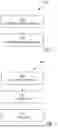
BRIEF DESCRIPTION OF THE DRAWINGS
Embodiments of the disclosure will be described in the following; references being made to the appended diagrammatical drawings which illustrate non-limiting examples of how the inventive concept can be reduced into practice.
FIG. 1 is a schematic view of a borehole with a fishing tool approaching a fish according to one example.
FIG. 2a is a cross-sectional side view of a fishing tool prior to engaging a fish according to an embodiment.
FIG. 2b is a cross-sectional side view of the fishing tool shown in FIG. 2a arranged in position to engage the fish.
FIG. 2c is a cross-sectional side view of the fishing tool shown in FIGS. 2a and 2b when engaged with the fish.
FIG. 3 is an isometric view of a part of a fishing tool according to an embodiment.
FIG. 4 is a cross-sectional side view of a guiding structure of a fishing tool according to an embodiment.
FIGS. 5a-c are front views of a guiding structure according to different embodiments,
FIG. 6 is a schematic flow chart of a method for providing a fishing tool according to an embodiment.
FIG. 7 is a schematic flow chart of a method for operating a fishing tool according to an embodiment.
DETAILED DESCRIPTION OF THE DISCLOSURE
Hereinafter, certain embodiments will be described more fully with reference to the accompanying drawings. The disclosure can, however, be embodied in many different forms and should not be construed as limited to the embodiments set forth herein; rather, these embodiments are provided by way of example so that this disclosure will be thorough and complete, and will fully convey the scope of the disclosure, such as it is defined in the appended claims, to those skilled in the art.
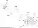
In FIG. 1, a drilled well 1 is shown. The well 1 consists of a drilled borehole 3 leading down into the bedrock to extract gas and/or oil. The well 1 can be reinforced and/or cased or lined as is well-known in the art.
FIG. 1 shows the well 1 in a position where it is subjected to a submerged fishing tool 100. The fishing tool 100 is configured for intervening with a fish 200 left downhole.
The fishing tool 100 is connected to a running structure such as a wireline 20, i.e., a cable adapted to follow the fishing tool 100 up and down the well 1. The wireline 20 is attached to the fishing tool 100 at one end, while the other end of the wireline 20 is connected to some equipment above the well 1. In this way, the position of the fishing tool 100 in the well 1 can be controlled by maneuvering the wireline 20.
In addition to mechanically guiding the fishing tool 100, the wireline 20 can be electrically coupled to the fishing tool 100 so that the fishing tool 100 can be powered via the wireline 20. The wireline 20 thus provides the fishing tool 100 with the necessary power so that the fishing tool 100 can perform its intended fishing operation downhole.
In the shown example, the wireline 20 forms a running structure used to follow the fishing tool 100 up and down a borehole 3 and to pull the fishing tool 100 out of the well 1. It should, however, be realized that the running structure 20 can be implemented in many different ways, such as by coiled tubing, and the like.
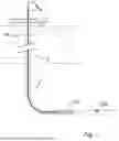
Now turning to FIGS. 2a to 2c, further details of the fishing tool 100 are shown, especially during a fishing operation. The fishing tool 100 has a drive end 102 arranged closest to the surface and an engagement end 104 arranged closest to the fish 200. Hence, the drive end 102 is a proximal end, while the engagement end 104 is a distal end. Typically, the drive end 102 is in direct connection with the running structure 20, or it can be indirectly connected to the running structure 20 via one or more downhole tools such as an anchoring unit, a stroking unit, a driving unit, or a conveyance unit, e.g., a tractor, and the like. The stroking unit provides an axial force for pulling the fish, the anchoring unit or conveyance unit provides an anchoring of the fishing tool 100 downhole, and the driving unit or conveyance unit propels the fishing tool 100 forward in the well 1, especially during a horizontal part of the well 1.
A support body 106 extends between the drive end 102 and the engagement end 104. The length of the support body 106 can be of any suitable magnitude, but preferably the support body 106 is as short as possible while still providing an axial length required to accommodate various functions of the fishing tool 100, as will be described later.
In the shown example, the borehole 3 is substantially horizontal. The fishing tool 100 is arranged at the vertical bottom of the borehole 3, which can be cased with a tubing. As is also shown in FIG. 2a, the fish 200 is arranged centrally in the borehole 3, which means that the fishing tool 100 is non-aligned with the fish 200. The fishing tool 100 can also be off-center of the borehole 3/tubing, and the fish can be arranged more coincident with the center of the borehole 3/tubing.
In FIG. 2a, the fishing tool 100 is shown in a position approaching the fish 200. The engagement end 104 of the fishing tool 100 comprises a guiding structure 110. The guiding structure 110 is preferably non-symmetrical and configured to guide the fishing tool 100 into an engagement position relative to the fish 200.
The guiding structure 110 is spear-shaped, i.e., it comprises an apex 112. The apex 112 is arranged off-center in relation to a longitudinal axis L of the fishing tool 100. The guiding structure 110 is further oriented so that the apex 112 is aligned with the fish 200, i.e., the location of the apex 112 is so that the apex 112 will meet the fish 200.
As is indicated in FIG. 2a, when the fishing tool 100 reaches the fish 200, the apex 112 of the guiding structure 110 will be received by an opening in the fish 200. A conical shape (or rather an oblique conical shape) of the guiding structure 110, i.e., slanted side walls 114, will guide the front part of the fishing tool 100 further into the fish 200, thereby causing the front part of the entire fishing tool 100 to move vertically upwards in the horizontal borehole 3. Hence, in order to engage with the fish 200, it is required that the apex 112 will actually be aligned with the opening of the fish 200. Appropriate location of the entire fishing tool 100 is achieved by the fishing tool 100 driving further into the fish 200 and using the slanted side walls 114 of the guiding structure 110 to move the fishing tool 100.
Immediately behind the guiding structure 110, a grappling device 120 is provided. At least the grappling device 120 of the front part of the fishing tool 100 will enter the fish 200 to a position indicated in FIG. 2b.
The grappling device 120 preferably forms part of the support body 106; optionally, it can form part of the engagement end 104. The grappling device 120 comprises a conical drive part 122 and one or more moveable grapples 124 arranged on the exterior side of the conical drive part 122. The conical drive part 122 extends along the longitudinal axis L to the guiding structure 110, at which interface the conical drive part 122 has a maximum diameter. Hence, the conical drive part 122 forms an end part of the support body 106. The grapple(s) 124 are in the form of axially moving latching dogs, which are configured to slide on the conical drive part 122. The latching dogs can be arranged on the ends of latching fingers, which allow the latching dogs to move radially when sliding on the conical drive part 122.
The idle position of the grapple(s) 124 is defined by a stop flange 126, behind which the grapple(s) 124 cannot move. The diameter of the stop flange 126 is further dimensioned to be greater than the fish 200, so that the stop flange 126 will also form a stop for the fishing tool 100 when it enters the fish 200.
For robust engagement with the fish 200, the grapple(s) 124 will be actuated to move forward, i.e., towards the guiding structure 110. For this, any kind of actuator 130 can be used, such as an electrically powered actuator, a hydraulic actuator, or an electromechanical actuator. Optionally, the grapple(s) 124 can be self-actuated by providing a pushing force on the stop flange 126 caused by the fishing tool 100 being urged to move further into the fish 200.
The actuator 130 can be a rotation-to-linear convertor converting rotation of an electric motor to an axial movement for sliding the grapple(s) 124 along the conical drive part 122 and thus into engagement with the fish 200. The rotating shaft is provided with a threaded section. On the threaded section of the rotating shaft, a nut is arranged. The threaded section and the nut form a rotation-to-linear converter which converts the rotary movement of the electric motor into a linear movement for sliding the grapple(s) 124 along the conical drive part 122 and thus into engagement with the fish 200. The linear movement of the nut is parallel to the longitudinal axis L of the tool 100. The pump can also form the rotation-to-linear converter.
An engagement position of the grapple(s) 124 is shown in FIG. 2c. In this position, the grapple(s) 124 has/have been urged forward, moving along the conical drive part 122, thereby extending the diameter of the grapple(s) 124 until it/they come(s) into contact with the interior of the fish 200. The grapple(s) 124 can be provided with grooves or teeth 128 in order to create a robust engagement with the fish 200. Upon proper engagement with the fish 200 after the grapple(s) 124 has/have been brought into engagement, the fishing tool 100 can be pulled up, thereby bringing the fish 200 to the surface.
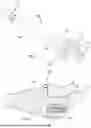
To further explain the fishing tool 100, it is realized that the location of the fish 200 can be off-center with regard to the longitudinal axis L of the fishing tool 100. It is further realized that a symmetrical fishing tool 100 having the apex 112 of the guiding structure 110 coinciding with the longitudinal axis L of the fishing tool 100 can fail to engage with the fish 200.
The guiding structure 110 is therefore configured as an oblique cone, which is shown in FIG. 3. It should be noted that in the figure, the grapple(s) and the stop flange are omitted. This means that the apex 112 will be displaced radially in relation to the longitudinal axis L. In the shown example, which also corresponds to the embodiment described with reference to FIGS. 2a to 2c, the apex 112 is located vertically above the longitudinal axis L. Further, in order to ensure the correct orientation of the guiding structure 110, the guiding structure 110 is rotationally self-aligning. Preferably, the guiding structure 110 is rotationally self-aligning with regard to the rest of the fishing tool 100, such as the drive end 102. This means that even if the fishing tool 100 gets twisted or starts to rotate, the desired position of the apex 112 will always be ensured. The rotationally self-aligning guiding structure 110 is arranged further away from the drive end 102 than a middle part of the fishing tool 100.
Self-aligning of the guiding structure 110 is preferably accomplished by allowing the guiding structure 110 to be rotationally supported on the engagement end 104, and by designing the guiding structure 110 so that its center of mass causes an automatic rotation of the guiding structure 110. The guiding structure 110 is thus rotationally non-symmetrical due to its oblique shape.
The eccentric center of mass can be achieved in various ways, for example, by using different materials or densities across the guiding structure 110 or a mass arranged in the guiding structure 110 to provide extra weight in that part and ensure the position of the center of mass. The mass can be made of a material having a higher density than the material of the remaining part of the guiding structure 110. In the shown example, the guiding structure 110 comprises a hollow portion 116. While the bottom part of the guiding structure 110 is solid, the upper part, at which the apex 112 is located, is formed by substantially less material. In fact, the upper part of the guiding structure 110 comprises a frame structure 118 forming a robust and rigid definition of the apex 112, although being of substantially less weight than the bottom portion of the guiding structure 110.
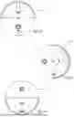
In FIG. 4, the fishing tool 100, in particular the engagement end 104, is shown in cross-section. The engagement end 104 comprises a support shaft 140. The guiding structure 110 is rotationally supported on the support shaft 140, and a bearing can be arranged therebetween. Preferably, the support shaft 140 is arranged centrally in the fishing tool 100, so that the support shaft 140 extends symmetrically along the longitudinal axis L. A key part 142 is axially clamped on the support shaft 140, and the guiding structure 110 is attached to the key part 142, for example, using a screw 144. The axial clamping of the key part 142 prevents the guiding structure 110 from moving axially off the support shaft 140. Notably, the key part 142 is free to rotate around the support shaft 140. Axial clamping of the key part 142 can, for example, be accomplished by providing a radial groove in the support shaft 140.
Now turning to FIGS. 5a-c, some examples of the guiding structures 110 will be described. As explained above, the guiding structure 110 has a center of mass M located off-center in relation to the longitudinal axis L of the fishing tool 100.
In FIG. 5a, a guiding structure 110 is shown where the apex 112 is located vertically above the center of mass M. Preferably, as measured from the longitudinal axis L, the apex 112 is arranged at an angle of 160°-200°, preferably around 180°, from the center of mass M. Thus, the apex 112 is located at an angle of 160°-200° from the center of mass M along a circle, such as a circumference of the guiding structure 110, and the circle having a circle center coincident with the center axis of the fishing tool 100.
In FIG. 5b, a guiding structure 110 is shown where the apex 112 is located vertically above and sideways of the center of mass M. Preferably, as measured from the longitudinal axis L, the apex 112 is arranged at an angle of 70°-110°, preferably around 90°, from the center of mass M.
In FIG. 5c, a guiding structure 110 is shown where the apex 112 is located vertically above the center of mass M but vertically below the longitudinal axis L. Preferably, as measured from the longitudinal axis L, the apex 112 is arranged at an angle of −20° to +20°, preferably around 0°, from the center of mass M.
In FIG. 6, a method 300 for providing a fishing tool 100 is schematically shown. The method 300 comprises providing 302 the guiding structure 110 having an eccentric center of mass M and rotationally supporting 304 the guiding structure 110 at the engagement end 104 of the fishing tool 100 so that the guiding structure 110 is self-aligning.
The center of mass M can be provided by a mass, such as the key part 142. Even though not shown, the mass can be rotationally arranged within the guiding structure 110, and the angle along a circumference of the guiding structure 110 can be controlled by a control unit so as to move the center of mass M, e.g., from a position shown in FIG. 5a to a position shown in FIG. 5b or 5c. The control unit can be controlled from the surface, or the fishing tool 100 can be preprogrammed to try different angles between the apex 112 and the center of mass M downhole if not successful in the pre-set position, i.e., if the fish 200 is not arranged off-center as predicted. By changing the position of the mass, the center of mass M is also changed, and the guiding structure 110 is still self-aligning.
In FIG. 7, a method 310 for operating a fishing tool 100 is schematically shown. The method 310 comprises providing 300 the fishing tool 100 according to the method 300 described with reference to FIG. 6. The method 310 further comprises engaging 312 the fishing tool 100 with a downhole fish 200 and extracting 314 the fishing tool 100 and the engaged fish 200 from downhole.
Modifications and other variants of the described embodiments will come to mind to one skilled in the art, having the benefit of the teachings presented in the foregoing description and associated drawings. Therefore, it is to be understood that the embodiments are not limited to the specific example embodiments described in this disclosure, and that modifications and other variants are intended to be included within the scope of this disclosure.
Furthermore, the labelling of a first element does not imply the presence of a second element and vice versa.
It is to be noted that the word “comprising” does not necessarily exclude the presence of other elements or steps than those listed.
It is also to be noted that the words “a” or “an” preceding an element do not exclude the presence of a plurality of such elements.
It should further be noted that any reference signs do not limit the scope of the claims.
By “casing” or “well tubular metal structure” is meant any kind of pipe, tubing, tubular, liner, string, and the like, used downhole in relation to oil or natural gas production.
Although features have been shown and described, it will be understood that they are not intended to limit the claimed disclosure, and it will be made obvious to those skilled in the art that various changes and modifications can be made without departing from the spirit and scope of the claimed disclosure. The specification and drawings are, accordingly, to be regarded in an illustrative rather than restrictive sense. The claimed disclosure is intended to cover all alternatives, modifications, and equivalents.
Claims
What is claimed is:1. A fishing tool comprising:
a drive end to be connected to an associated running structure; and
an engagement end configured to engage with a fish located downhole,
wherein the engagement end comprises a guiding structure that is rotationally self-aligning and non-symmetrical.
2. The fishing tool according to claim 1, wherein the guiding structure is rotationally self-aligning in relation to the drive end.
3. The fishing tool according to claim 1, further comprising a support body extending between the drive end and the engagement end, wherein the support body comprises at least one grappling device.
4. The fishing tool according to claim 3, wherein the grappling device comprises a conical drive part, and wherein at least one grapple is arranged to slide on the conical drive part.
5. The fishing tool according to claim 1, wherein the engagement end comprises a support shaft, and wherein the guiding structure is rotationally supported on the support shaft.
6. The fishing tool according to claim 5, wherein the support shaft is arranged centrally in the fishing tool.
7. The fishing tool according to claim 1, wherein the guiding structure has a center of mass located off-center in relation to a longitudinal axis of the fishing tool.
8. The fishing tool according to claim 1, wherein the guiding structure comprises an apex.
9. The fishing tool according to claim 8, wherein the apex is located at an angle of 160° to 200° from the center of mass.
10. The fishing tool according to claim 8, wherein the apex is located at an angle of −20° to +20° from the center of mass.
11. The fishing tool according to claim 8, wherein the apex is located at an angle of 70° to 110° from the center of mass.
12. The fishing tool according to claim 1, wherein the guiding structure comprises a hollow portion.
13. A method for providing a fishing tool, comprising:
providing a guiding structure having an eccentric center of mass and being rotationally non-symmetrical; and
rotationally supporting the guiding structure at an engagement end of the fishing tool so that the guiding structure is self-aligning.
14. A method for operating a fishing tool, comprising:
providing a guiding structure having an eccentric center of mass and being rotationally non-symmetrical;
rotationally supporting the guiding structure at an engagement end of the fishing tool so that the guiding structure is self-aligning;
engaging the fishing tool with a downhole fish, and
extracting the fishing tool and the engaged fish from downhole.
Images & Drawings included:

Sources:
- United States Patent and Trademark Office - verify current appl. status at the USPTO↗
Similar patent applications:
- » 20120103691
Methods of coupling components of downhole tools, downhole tools and components of downhole tools - » 20190017346
Stock shape for downhole tool component, downhole tool component, and downhole tool - » 20220162918
Downhole apparatus for reducing rotational and linear friction between a downhole tool and/or a downhole tool string comprising the downhole tool and a wall of a wellbore - » 20170284167
DOWNHOLE TOOL CONTAINING DOWNHOLE-TOOL MEMBER CONTAINING REACTIVE METAL AND DOWNHOLE-TOOL MEMBER CONTAINING DEGRADABLE RESIN COMPOSITION, AND WELL-DRILLING METHOD - » 20250244497
NMR-BASED LITHIUM MEASURING AND MONITORING DOWNHOLE TOOLS, METHODS OF USING SAID DOWNHOLE TOOLS, AND METHODS OF MEASURING LITHIUM CONCENTRATIONS BASED ON NMR MEASUREMENTS ACQUIRED BY SAID DOWNHOLE TOOLS - » 20160108165
Rubber member for downhole tools, downhole tool, and method for recovering hydrocarbon resource - » 20090065191
Support assembly for downhole tool, downhole tool and method - » 20160290091
DEGRADABLE SEAL MEMBER FOR DOWNHOLE TOOLS, DOWNHOLE TOOL, AND METHOD OF WELL DRILLING AND COMPLETION - » 20120080230
Bearings for downhole tools, downhole tools incorporating such bearings, and methods of cooling such bearings - » 20170241208
Bearings for downhole tools, downhole tools incorporating such bearings, and related methods
Recent applications in this class:
- » 20250354448 2025-11-20
Apparatus To Move An Object In An Open Hole Section of A Wellbore - » 20250243724 2025-07-31
MECHANICAL FISHING TOOL WITH A BUILT-IN CAMERA - » 20240328273 2024-10-03
METHOD AND SYSTEM FOR RETRIEVING A WHIPSTOCK WITH A DRILL BIT IN A WELLBORE - » 20240141743 2024-05-02
Systems and methods for running tubulars - » 20240044220 2024-02-08
METHOD FOR PULLING CASING - » 20230383616 2023-11-30
ADJUSTABLE FISHING GRAPPLE TOOL - » 20230193716 2023-06-22
Expandable overshot-spear tool - » 20230061851 2023-03-02
Improvements In Or Relating To Wellbore Operations - » 20230039813 2023-02-09
RELEASABLE RETRIEVING TOOL WITH LUG AND SLOT CONNECTION - » 20220243548 2022-08-04
Systems and methods for running tubulars
Recent applications for this Assignee:
- » 20260098467 2026-04-09
METHOD OF DETERMINING THE POSITION OF A DOWNHOLE TOOL IN A BOREHOLE - » 20260071512 2026-03-12
DOWNHOLE PACKER ASSEMBLY - » 20250003305 2025-01-02
DOWNHOLE WIRELINE TOOL - » 20240392640 2024-11-28
DOWNHOLE RADIAL FORCE TOOL ASSEMBLY - » 20230340847 2023-10-26
Downhole tool string - » 20230295994 2023-09-21
WIRELINE EXPANSION TOOL - » 20230112756 2023-04-13
Downhole self-propelling wireline tool - » 20230112474 2023-04-13
Hydraulically driven downhole self-propelling wireline tool - » 20230110460 2023-04-13
Hydraulically driven downhole self-propelling wireline tool string - » 20230064823 2023-03-02
Downhole tool