OUTLET GUIDE VANE DEVICE FOR A VENTILATOR, AND VENTILATOR COMPRISING AN OUTLET GUIDE VANE DEVICE
US20260104059A1
2026-04-16
19/116,835
2023-09-21
Smart Summary: An outlet guide vane device is designed for use in a ventilator. It features an impeller with blades that help move air. The device includes a housing and at least one guide vane with inner blades. This guide vane is supported by an intermediate ring, which is held in place by three strut blades evenly spaced around it. Additionally, the ventilator is equipped with this outlet guide vane device to improve its performance. 🚀 TL;DR
Abstract:
The present disclosure relates to an outlet guide vane device for a ventilator which has at least one impeller having impeller blades and the device includes outer housing and at least one guide vane with inner guide blades, wherein the guide vane has an intermediate ring which is held preferably concentrically in/on the housing by means of at least three strut blades distributed over the circumference. The present disclosure additionally relates to a ventilator comprising a corresponding outlet guide vane device.
Inventors:
- Sandra Hub 6 🇩🇪 Pfedelbach, Germany
- Tobias Gauss 4 🇩🇪 Niedernhall, Germany
- Frieder Loercher 23 🇩🇪 Braunsbach, Germany
- Daniel SEIFRIED 2 🇩🇪 Rosengarten, Germany
- Matthias SCHMITT 1 🇩🇪 Forchtenberg, Germany
Applicant:
Interested in similar patents?
Get notified when new applications in this technology area are published.
Classification:
F04D29/542 » CPC main
Details, component parts, or accessories; Casings; Connections of working fluid for axial pumps; Fluid-guiding means, e.g. diffusers; Specially adapted for elastic fluid pumps Bladed diffusers
F04D29/54 IPC
Details, component parts, or accessories; Casings; Connections of working fluid for axial pumps Fluid-guiding means, e.g. diffusers
Description
CROSS REFERENCE
This application is a national stage entry application under 35 U.S.C. 371 of PCT Patent Application No. PCT/DE2023/200194 filed on 21 Sep. 2023, which claims priority to German Patent Application No. 10 2022 210 553.2, filed on 6 Oct. 2022 the entire contents of each of which are incorporated herein by reference.
FIELD
The present disclosure relates to an outlet guide vane device for a ventilator which has at least one impeller includes impeller blades, and includes an outer housing and at least one outlet guide wheel with inner guide vanes, wherein the outlet guide wheel has an intermediate ring, which is held, in an embodiment concentrically, in/on the housing by means of at least three strut vanes distributed over the circumference. The present disclosure furthermore relates to a ventilator having a corresponding outlet guide vane device.
BACKGROUND
Ventilators having outlet guide vane devices are sufficiently well known in practice. Purely by way of example, reference may be made in this regard to WO 2020/015792 A1. Such ventilators having outlet guide vane devices, in particular having inner guide vane devices, are problematic in practice. The outlet guide vane devices extend from the axis only over one region of the area through which flow occurs. Generally, they combine a relatively high static efficiency with low noise output values since outlet guide vanes, which may in particular generate strong blade passing noises, are not present in the outer region that is decisive for this. Irrespective of this, the motor-impeller of the ventilator and the inner outlet guide wheel must be held somehow. The holding or suspension of the outlet guide vane device is generally complex, reduces efficiency and promotes noise generation. Moreover, mechanical stresses and deformations occur in relation to the holding means implemented hitherto during operation of the ventilator and during transportation, often leading to damage.
SUMMARY
It is the underlying object of the present disclosure, at least as far as possible, to eliminate the disadvantages which occur in the prior art. On the one hand, damage to the outlet guide wheel and to the ventilator induced by mechanical stresses should be avoided. On the other hand, noise generation and losses of efficiency should be minimized. In addition, the outlet guide vane device according to the present disclosure should differentiate itself from competing products. The same applies to the ventilator according to the present disclosure.
In respect of the outlet guide vane device, the above object is achieved by the features of claim 1, in an embodiment. In respect of the ventilator according to the present disclosure, the object is achieved by the features of additional independent claim 14, in an embodiment, according to which the ventilator according to the present disclosure includes an outlet guide vane device according to the present disclosure. Ultimately, the central focus here is on the outlet guide vane device and the design features thereof.
The outlet guide vane device according to the present disclosure is used for installation in a ventilator, which may be an axial, radial or diagonal ventilator. The ventilator includes at least one impeller having a plurality of impeller blades. As regards the fundamental construction of such a ventilator, reference may be made, purely by way of example, to WO 2020/015792 A1, which has already been mentioned above. Given the reference to the known ventilator, no description of such a ventilator is provided here.
According to the present disclosure, the outlet guide vane device includes an outer housing, in which an outlet guide wheel with inner guide vanes is arranged. The outlet guide wheel has an intermediate ring, at which the inner guide vanes end. To be more precise, the inner guide vanes extend between a hub ring or inner ring of the outlet guide vane device and the intermediate ring, such that the guide vanes are arranged in a fixed manner there.
It is therefore very particularly significant that the intermediate ring of the outlet guide wheel is held, in an embodiment concentrically, in or on the housing by means of at least three strut vanes distributed over the circumference. The strut vanes provide a holding or fixing function and act between the intermediate ring and the inside of the outer housing. Moreover, they are embodied in the manner of blades and are specifically optimized with regard to air flow while, at the same time, having optimized strength.
Additional embodiments of the claimed teaching are obtained as follows:
The individual components of the outlet guide vane device can be manufactured integrally by casting, in particular including the guide vanes, which are connected by the strut vanes, via the intermediate ring, to the inner surface of the housing and thus to the outer housing contour. The strut vanes have a load-bearing function combined with a flow-optimized configuration.
More specifically, the strut vanes can have a pronounced slant with respect to the blade trailing edge of the impeller or with respect to an imaginary radial line. They can be arranged at a relatively large distance from the impeller blade trailing edge. This distance can be greater when viewed in the axial direction than the axial extent of the strut vanes, for example.
Moreover, the number of strut vanes is relatively small, smaller than the number of inner guide vanes, in an embodiment.
An important point is that the strut vanes have a relatively small effective area in terms of fluid dynamics in comparison with the inner outlet guide vanes. The strut vanes are relatively thick in order to ensure the required stiffness both during transportation of a corresponding ventilator and in operation.
When viewed in profile section, e.g. in section at a cylinder shell coaxial with the ventilator axis, the strut vanes are angled and aligned in such a way that they pose as little flow resistance as possible to a swirling flow emerging from the impeller of the ventilator. It is of advantage if, geometrically speaking, no flow deflection or at most a small flow deflection takes place at each strut vane.
As a further option, the strut vane is fastened or formed on the outer housing in the region of a diffuser, as far as possible at a location remote from a diffuser inlet. It is advantageous, in an embodiment, if the undercut region which is formed, which tends to be relatively large, is not filled with a demolding wedge, demolding instead being carried out by means of a special demolding strategy with the aid of slides. To this extent, possible efficiency losses and noise generation due to demolding wedges formed integrally on the component are avoided while production is a simple process in terms of injection molding.
In the outlet guide vane device according to the present disclosure, the strut vanes extending between the intermediate ring and the outer housing are set at a relatively pronounced slant with respect to the blade edge of the impeller or relative to imaginary radial lines, when viewed parallel to the ventilator axis, with no flow deflection being caused. Since the strut vane is at a relatively great distance from the impeller blade trailing edges, possible noise generation at the strut vanes is avoided or minimized.
It is also conceivable for the outlet guide vane device to be equipped with a cooling structure, this in an embodiment being assigned to the outlet guide wheel. To be specific, the cooling structure can be integrated integrally into the outlet guide wheel. The cooling structure is used to provide a cooling flow as a result of the operation of the ventilator by way of a pressure difference. By means of this measure, heat is dissipated from the electric motor. Heat dissipation entails cooling.
The outlet guide vane device according to the present disclosure is thus advantageous in respect of stability/strength and in respect of reducing efficiency losses and noise generation. These advantages are achieved by surprisingly simple design measures in accordance with the above explanations.
There are then various possibilities for refining and developing the teaching of the present disclosure in an advantageous manner. For this purpose, reference may be made, on the one hand, to the claims that follow claim 1 and, on the other hand, to the following explanation of exemplary embodiments of an outlet guide vane device according to the present disclosure and of a corresponding ventilator with reference to the drawing. In combination with the explanation of the exemplary embodiments of the present disclosure with reference to the drawing, refinements and developments of the teaching are also explained in general terms.
BRIEF DESCRIPTION OF THE DRAWINGS
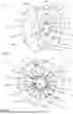
FIG. 1 shows, in a perspective view from the outflow side, a ventilator having a load-bearing outlet guide vane unit according to the present disclosure including a housing, an outlet guide vane device and strut vanes,
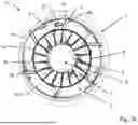
FIG. 2a shows, in a level axial plan view from the outflow side, the ventilator including the load-bearing outlet guide vane unit from FIG. 1,
FIG. 2b shows a detail view from FIG. 2a in the region of the strut vanes, wherein the profile of the strut vanes, the profile of the ventilator blade and a radial line are each illustrated as characteristic curves in a projection onto the plane of the view,
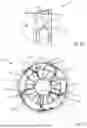
FIG. 3 shows, in a level axial plan view from the inflow side, the ventilator including the load-bearing outlet guide vane unit from FIGS. 1 and 2a,
FIG. 4a shows, in a side view and in section at a plane through the axis, the ventilator including the load-bearing outlet guide vane unit according to FIGS. 1, 2a and 3 with schematically indicated dimensions in the region of the inlet nozzle,
FIG. 4b shows a detail view from FIG. 4a in the region of the strut vanes, wherein three characteristic variables are indicated schematically,
FIG. 4c shows another detail view from FIG. 4a in the region of the strut vanes, wherein undercut regions with regard to demolding from a casting mold in directions parallel to the ventilator axis are indicated schematically by hatching,
FIG. 5a shows, in a side view and in section at a plane parallel to the axis and to the plane of the illustration, the ventilator including the load-bearing outlet guide vane unit according to FIGS. 1, 2a, 3 and 4a, wherein it is possible to see a strut vane,
FIG. 5b shows a detail view from FIG. 5a in the region of the visible strut vane, wherein four characteristic variables are indicated schematically,
FIG. 6a shows, in a side view and in section at a plane through the axis, another embodiment of a load-bearing outlet guide vane unit, wherein demolding wedges are formed in the region of the diffuser to allow easier demolding,
FIG. 6b shows a detail view from FIG. 6a in the region of a strut vane with a demolding wedge,
FIG. 7a shows, in a level axial plan view, when viewed from the outflow side, a ventilator including another embodiment of a load-bearing outlet guide vane unit, wherein profiles of flow disturbances in the wake of the impeller, which have been obtained by means of a flow simulation, are indicated on a plane perpendicular to the axis slightly downstream of the impeller blade trailing edges, and
FIG. 7b shows the ventilator in the same flow state as FIG. 7a, wherein the flow disturbances are now illustrated in a plane perpendicular to the ventilator axis but at a greater distance from the impeller blade trailing edge, still upstream of but close to the strut vane leading edge.
DETAILED DESCRIPTION OF THE DISCLOSURE
FIG. 1 shows, in a perspective view from the outflow side, a ventilator 57 of axial construction with one exemplary embodiment of a load-bearing outlet guide vane unit 1. The outlet guide vane unit 1 consists, in particular, of a housing 2, an intermediate ring 5, a hub ring 4, inner guide vanes 11 extending between the hub ring 4 and the intermediate ring 5, and strut vanes 3, 3a extending between the intermediate ring 5 and the housing 2 or the diffuser region 10 thereof.
It is advantageous, in an embodiment, if the outlet guide vane unit 1 is produced in one piece in a casting process, advantageously by injection molding of plastic. The housing 2 defines the outer boundary of a flow through the ventilator taking place within the housing 2. The housing 2 includes various regions, first of all, when viewed in the direction of flow, an inlet nozzle 9, then an advantageously cylindrical region 29, within which the impeller 19 with its blades 22 is arranged, and a diffuser region 10, on which the strut vanes 3, 3a are fastened.
An inner outlet guide vane device consisting, in particular, of inner outlet guide vanes 11 that affect the fluid dynamics, which extends between the hub ring 4 and the intermediate ring 5, is arranged within the housing 2 downstream of the impeller 19. Owing to the effect of the inner outlet guide vanes 11 on the flow in interaction with the intermediate ring 5 and the hub ring 4, the efficiency and air output of the ventilator 57 is particularly high. The motor 34 is fastened by means of its stator 36 on the hub ring 4, radially within the latter, in the mounting region 8, and therefore the inner outlet guide vanes 11 and the intermediate ring 5 also exercise a load-bearing function for the motor 36 and ultimately also the impeller 19.
In order to hold the motor 34 with the impeller 19 and the inner outlet guide vane device on the outer housing 2, the outer strut vanes 3, 3a are provided. These have at most a subordinate function in terms of the fluid dynamics and serve predominantly to fasten the inner outlet guide vane device and thus the motor 34 and the impeller 19 on the outer housing 2. Their design is advantageous in terms of noise, and therefore only a little additional noise, if any, is generated by their presence during the operation of the ventilator 57. Overall, two different through-flow regions, an outer through-flow region 6 between the intermediate ring 5 and the diffuser wall 10 of the housing 2, and an inner through-flow region 7 between the hub ring 4 and the intermediate ring 5, are formed within the housing 2 in the axial region of the diffuser 10 when viewed in the direction of the span (from the hub 4 to the diffuser 10). The inner through-flow region 7 has the load-bearing inner guide elements 11, which have a function in terms of fluid dynamics and, for example, reduce flow swirl, avoid or reduce hub backflow and, by virtue of their radially inner position, generate only a little noise.
The outer through-flow region 6 has the likewise load-bearing strut vanes 3, 3a, having 6 thereof in the exemplary embodiment, advantageously 4-8, which are distributed over the circumference and are embodied in a manner optimized for noise. In the exemplary embodiment, there is a means provided on the strut vane 3a for fastening cables that lead from the housing 2 to the motor. Flanges, which advantageously have various fastening means, are provided on the inflow and outflow sides in the edge regions of the housing 2 on the load-bearing outlet guide vane unit 1. On the inflow-side flange, there are fastening means 20 for fastening the outlet guide vane unit 1 and thus the ventilator 57 on a higher-level apparatus or system, and on the outflow-side flange there are likewise fastening means 21 for fastening the outlet guide vane unit 1 on a higher-level apparatus or system. Fastening means 25 for a finger-proof grille are furthermore provided on the outflow-side flange, and said means can also be provided similarly on the inflow-side flange. The finger-proof grilles can be screwed on in region 25 in a recessed manner such that they do not protrude axially beyond the outlet guide vane unit 1, and this leads to good ease of handling and good stackability of the ventilators 57.
At its outflow-side edge 12, the intermediate ring 5 is of corrugated design, and may also be of serrated or slotted design. It can also be of circular design without corrugation.
Within the hub ring 4, in the mounting region 8, the motor is attached to a motor support flange 59 (FIG. 2), which is attached integrally in one piece to the load-bearing outlet guide vane device 1. To reinforce and stabilize the connection to the motor, reinforcing ribs 58 are additionally attached within the mounting region 8.
In the mold for manufacturing the load-bearing outlet guide vane unit 1, it is conceivable to provide interchangeable inserts in the region within the hub ring 4, i.e. in the mounting region 8, in order to obtain different interfaces with different motors. Apart from the circle of holes for fastening the motors, it is also possible here, for example, for the axial screw-fastening plane for the motor, and the axial position of the motor support flange 59 within the mounting region 8 to vary.
In the azimuthal region of the strut vane 3a with the means for fastening the cables, the intermediate ring 5 and the hub ring 4 have cutouts for laying the electric connection cables to the stator 36 of the motor 34, which is advantageously an external rotor motor and, as a further advantageous option, is embodied as an EC motor, for instance with integrated motor electronics. In this region, the housing 2 also has a cutout 50 to enable the cables to be passed through (as illustrated, for example, in FIG. 5a).
FIG. 2a shows, in axial plan view and from the outflow side, the ventilator 57 including the load-bearing outlet guide vane unit 1 according to FIG. 1. Supplementing the information relating to FIG. 1, the outer through-flow region 6, which is traversed by the strut vanes 3, 3a, and the inner through-flow region 7 with the inner guide vanes 11 are clearly visible. During the operation of the ventilator 57, the impeller 22 with the blades 19 rotates in a counterclockwise direction of rotation 32 around the ventilator axis. In the mounting region 8, the motor 34 is attached to a motor support flange 59 by means of fastening means 18, in an embodiment, screws.
The diffuser region 10 widens from the region 29 for the impeller 19 (see also FIG. 1) towards the outflow-side edge of the housing 2. The intermediate ring 5 also widens slightly, starting from the impeller 19, toward its outflow-side edge 12 (FIGS. 1 and 4a, 4b). As a result, the inner through-flow region 7 and the outer through-flow region 6 in the exemplary embodiment are of diffuser-type design, i.e. they are designed to widen in the through-flow direction. This is advantageous for a high pressure recovery downstream of the impeller 19 and thus for a high static efficiency of the ventilator 57.
FIG. 2b shows a detail view of FIG. 2a in the region of a strut vane 3, wherein the characteristic radial profile 24 of the strut vane or vanes 3, 3a, the characteristic radial profile 26 of the impeller blade or blades 22, and a radial line 31 are each illustrated as characteristic curves in a projection onto the plane of the view. Here, the radial profile 24 of the strut vanes 3, 3a is illustrated by means of a center line of the strut vanes 3, 3a, e.g. a center line derived from the radial profile of the leading edge 46 of the strut vanes 3, 3a and the radial profile of the trailing edge 47 of the strut vanes 3, 3a when viewed in the given projection. It is also entirely possible simply to use either the profile of the leading edge 46 or of the trailing edge 47 in isolation, or to use an imaginary line connecting all the centroids of all the cylinder shell intersections of the strut vanes 3, 3a with cylinders coaxial with the ventilator axis.
The radial profile 26 of the impeller blade 22 is characterized on the basis of the profile of its trailing edge 39, wherein the serrated configuration of the impeller trailing edge 39 has not been taken into account, and a “smoothed” line has been used. In the case of the characteristic radial profile 26 of the impeller blades 22, it is also possible, for example, to use a center line derived from the radial profile of the leading and trailing edges or an imaginary line connecting all the centroids of all the cylinder shell intersections of the impeller blades 22 with cylinders coaxial with the ventilator axis.
In FIG. 2b, an angle γ 27 between the characteristic radial profile 24 of the strut vanes 3, 3a and the characteristic radial profile 26 of the impeller blades 22, at the illustrated point of intersection, is shown; as is an angle δ 28 between the characteristic radial profile 24 of the strut vanes 3, 3a and a radial line 31 starting from the ventilator axis. Depending on the relative position between the impeller blade 22 and the strut vane 3, 3a or depending on the location of the point of intersection under consideration when viewed in the radial direction, the angles δ 28 and γ 27 may vary somewhat. The mean angle over all possible points of intersection within the outer through-flow region 6 or the angle δ 28 or γ 27 at a point of intersection approximately in the radial center of the outer through-flow region 6 would be particularly relevant. For the sake of completeness, it should be clarified that, in the present reasoning, the angles δ 28 and γ 27 should always be understood in terms of absolute value without a sign. It is advantageous, in an embodiment, if the angle γ 27 in particular is large, in particular γ>30° or γ>45° in order to achieve minimization of noise generation, in particular blade passing noise generation. As a further advantageous option for the same purpose, in an embodiment, the angle δ 28 is also large, in particular δ>20° or δ>35°. A large angle δ 28 enables the stiffness of a load-bearing outlet guide vane device to be fundamentally reduced. However, the reinforcing effect of the intermediate ring 5 ensures a very high stiffness of the load-bearing outlet guide vane device 1, which can be constructed with adequate stiffness using 4-8 strongly slanted strut vanes 3, 3a without the risk that the impeller 19 will rub against the housing 2 or the mounting region 29 thereof for the impeller 19 during operation.
Furthermore, it would also be possible in the case of small angles δ 28 to provide a large angle γ 27 required for low blade passing noise generation. However, this would be possible only in the case of a radial profile 26 of the impeller blades 22 which was very strongly slanted with respect to the radial direction. It has been found that this is possible only to a limited extent with impeller blades 22 that are advantageously manufactured from injection molded plastic, in an embodiment, because of the radial deformations that then occur during the operation of the impeller blades 22, for which reason the choice of a sufficiently large angle δ 28 may be necessary and advantageous for low blade passing noise generation. In the exemplary embodiment, the strut vane 3 is tilted counter to the impeller blade direction of rotation 32 as it extends between the intermediate ring 5 and the diffuser 10. Since the angles γ 27 and δ 28 are large in terms of absolute value, it is equally conceivable that the strut vanes 3 are conversely tilted in the direction of rotation 32. In another conceivable embodiment, different strut vanes distributed over the circumferential direction can also be tilted alternately in and counter to the direction of rotation.
FIG. 3 shows, in a level axial plan view from the inflow side, the ventilator 57 including the load-bearing outlet guide vane unit 1 from FIGS. 1 and 2a. Supplementing the descriptions relating to FIGS. 1, 2a and 2b, the impeller 19 of the ventilator 57 with its blades 22, which are fastened to a common hub, are particularly clearly visible here. The impeller is advantageously manufactured in one piece by plastic injection molding. The blades 22 have a special configuration for noise reduction, in particular what are referred to as winglets 38 (see also FIGS. 4a, 4b), at their radially outer edges. Within the impeller 19 or the hub region thereof it is possible to see the rotor 35 of the motor 34, to which the impeller 19 is fastened and which drives the impeller 19 during the operation of the ventilator 57. For the aerodynamically and aeroacoustically advantageous configuration of the ventilator 57, there is furthermore in the hub region of the impeller 19 a hub hood 37 of advantageous configuration in terms of fluid dynamics attached to the hub of the impeller 19 (see also FIG. 4a). When viewed from the inflow side, the inflow-side edge 23 of the intermediate ring 5 of the outlet guide vane device as well as the inflow edge 13 of the inner outlet guide vanes 11 can be seen. In the view shown, the direction of rotation 32 is clockwise here.
FIG. 4a shows, in a side view and in section at a plane through the axis, the ventilator 57 including the load-bearing outlet guide vane unit 1 according to FIGS. 1, 2a and 3 with schematically indicated dimensions in the region of the inlet nozzle. Supplementing the relevant figures, the contour of the hub hood 37, which is attached in the region of the hub of the impeller 19 and is configured in an aerodynamically advantageous manner, being rounded and merging at a tangent into the hub of the impeller 19, is particularly clearly visible here. The motor 34, consisting of the stator 36 and the rotor 35, is illustrated schematically. The stator 36 is fastened to fastening devices 18 on the fastening flange 59 in the interior of the mounting region 8 of the load-bearing outlet guide vane unit 1. The impeller 19 or the hub thereof is fastened to the rotor 35 of the motor 34 by means of fastening means 30, using screws, in an embodiment.
The motor 34 and thus also the impeller 19 are thus held on the outer housing contour via the inner outlet guide vanes 11, the intermediate ring 5 and the strut vanes 3, 3a, for which reason the outlet guide vanes 11 and the strut vanes 3, 3a and, ultimately, the entire outlet guide vane unit 1 can be referred to as load-bearing. The impeller 19, together with its blades 22 and the radially outer ends thereof, which advantageously have a special contour, referred to as winglets 38, runs within the housing 2 axially at the level of a region 29, which is cylindrical, in an embodiment, wherein a small radial clearance and a flow gap are present between the impeller blade 22 with the winglets 38 and the region 29 of the housing 2.
The inner guide elements 11 have a configuration which is advantageous for manufacture by casting or for demolding from casting molds. In their inflow-side region 16, they include a region 16 matched to the inflow direction and angled relative to the axial direction and, in the region 15 of outflow, a region 15 which can be demolded in an axial direction without an undercut and are approximately in alignment axially. This configuration is advantageous in respect of the demoldability of the component referred to as the “load-bearing outlet guide vane unit 1” especially in conjunction with the slightly conical configuration of the intermediate ring 5, which widens radially in the through-flow direction.
The outlet guide vane unit 1 is of compact configuration radially. This means that the inlet diameter Da 45 of the inlet nozzle 9 (diameter Da 45 of the radially outer beginning of the curvature of the inlet nozzle 9) is relatively small in relation to the inside diameter Di 44, advantageously Da/Di<1.1. As a result, a relatively small extent e 43 of the outlet guide vane unit transversely to the ventilator axis is also made possible (the extent e 43 can be, in particular, the side length of a square contour extending transversely to the ventilator axis, within which the load-bearing outlet guide vane unit 1 and thus the ventilator 57 can be fitted). e/Di<1.2 is advantageous. As a result, when viewed transversely to its axis, the ventilator takes up a particularly small amount of installation space in respect of its inside diameter Di 44 and thus also in respect of the diameter of its impeller 19. Conversely, for a given installation space, a ventilator 57 with a particularly large inside diameter Di 44 and thus a particularly large outside diameter of the impeller 19 can be used, which may be advantageous acoustically at a given operating point.
When viewed in the radial direction, the outflow-side edge of the load-bearing outlet guide vane unit 1 advantageously does not project beyond the inflow-side edge. As a further advantage, the radial extent of the outflow-side edge and of the inflow-side edge of the load-bearing outlet guide vane unit 1 are very similar to one another, i.e. the inlet nozzle 9 on the inflow side and the diffuser region 10 on the outflow side each make maximum use of an available radial installation space or transport space (total radial installation space minus a necessary flange region) (see also FIG. 1). In addition, it is possible during transportation for several ventilators 57 with outlet guide vane units 1 of identical construction to be stacked on one another and fastened to one another entirely without problems, e.g. using the fastening means 20 and 21 (see FIG. 1), which can advantageously be at least partially congruent when viewed in a projection onto a plane perpendicular to the ventilator axis.
FIG. 4b shows a detail view from FIG. 4a in the region of a strut vane 3, wherein three characteristic variables are indicated schematically. The axial distance a 40 of the strut vane 3 or the inflow edge 46 thereof from the blade 22 of the impeller 19 or the outflow edge thereof is relatively large, in particular to ensure low blade passing noise generation. Here, it is also possible to use a mean distance over the radial extent of the strut vane 3 or the minimum axial distance a over the radial extent thereof as a. The axial extent b 41 of the strut vane 3, measured either on average over the radial extent or approximately in the radial center of the strut vane 3, is used as a reference variable for quantification. a/b is greater than 1.0 or, as a further possibility, >1.5, in an embodiment. In order to achieve a high static efficiency of the ventilator 57, the opening angle α 42 chosen on one side of the diffuser region 10 of the housing 2, in the case of curved profiles optionally on average over the diffuser profile, is large, α>10°, in an embodiment. This is possible on account of the presence of the intermediate ring 5, which likewise widens slightly radially in the through-flow direction, without having to accept flow separations in the region of the diffuser 10.
FIG. 4c shows another detail view of FIG. 4a in the region of a strut vane 3, wherein undercut regions 48, 49 with regard to demolding from a casting mold in demolding directions parallel to the ventilator axis are indicated schematically by hatching. The undercut regions 49 are regions of the diffuser 10 of the housing 2 on the inflow side of the strut vanes 3, 3a, wherein the strut vanes 3, 3a “cover” these regions 49 of the diffuser region 10 with respect to axial demolding of a shaping mold part of the outlet guide vane unit 1 which demolds toward the outflow side. Conversely, the diffuser region 10 covers the undercut regions 48 on the strut vanes 3, 3a with respect to axial demolding of a shaping mold part of the outlet guide vane unit 1 which demolds toward the inflow side. Particularly on account of the relatively large opening angle α 42 of the diffuser region 10 (see FIG. 4b), the undercut regions 48, 49 are relatively large and pronounced. Use is made of a special mold configuration which enables demolding of these undercut regions 48, 49 to avoid having to fill these with material or reconfigure them in some other way, which would result in disadvantages in efficiency and acoustics. For example, slides can be mounted on the shaping mold part which is demolded toward the inflow side and is pulled axially out of the component, it being possible for said slides to perform an optionally superimposed movement radially inward during demolding and thus to reproduce and shape the undercut regions 48, 49. It is also conceivable, during or before the demolding of the shaping mold part which is demolded toward the outflow side and is pulled axially out of the component, to employ a relative rotary motion between the mold and the component (i.e. the outlet guide vane unit 1) to enable the undercut regions 48, 49 to be demolded, e.g. by the application of a rotary motion of the component (i.e. the outlet guide vane unit 1) during the demolding process.
FIG. 5a shows, in a side view and in section at a plane parallel to the axis and to the plane of the illustration, the ventilator 57 including the load-bearing outlet guide vane unit 1 according to FIGS. 1, 2a, 3 and 4a, wherein, in particular, it is possible to see a strut vane 3 in section. The corrugated configuration of the outflow-side edge 12 of the intermediate ring 5 in the exemplary embodiment is clearly visible. Here, it can be seen that this edge 12 does not project axially beyond the housing 2 at any point and that the “corrugation troughs” lie axially somewhat within the housing at a short distance from the axial edge. As described in accordance with FIG. 1, a finger-proof grille can be mounted on the outflow side, and this advantageously does not project axially beyond the housing 2. Radially extending struts of such a finger-proof grille can then extend in the regions of the “corrugation troughs”, i.e. the recesses, of the outflow-side edge 12 of the intermediate ring 5. A recess 50 can also be seen in the housing 2, through which recess electric cables can be passed to the motor 34.
FIG. 5b shows a detail view from FIG. 5a in the region of the visible strut vane 3, wherein four characteristic variables are indicated schematically. The axial extent b 41 of the strut vane 3 has already been described with reference to FIG. 4b. Together with the thickness t 54 of the strut vane 3, it also plays an important role in respect of the stiffness and strength of the load-bearing outlet guide vane unit 1 since the relatively small number of, advantageously, 4-8 strut vanes 3 must, in particular, hold the entire motor 24, the impeller 19 and the inner guide arrangement including the intermediate ring 5, the hub ring 4 and the inner guide vanes 11 on the housing 2. It is significant that the moment of stiffness (area moment of inertia) of the strut vanes 3 is sufficiently large in section. To prevent the axial extent b 41 of the strut vanes 3 from becoming too large for reasons of low blade passing noise generation, the thickness t 54 of the strut vanes 3 is advantageously made relatively large. Quantitatively, it is advantageous to choose especially the maximum thickness t 54 of a strut vane 3 to be greater than 20% of its axial extent b 41. This in consideration of an aerodynamically advantageous configuration of the cross section of the strut vane 3, as seen in section or at an intersection with a cylinder shell coaxial with the ventilator axis. In such a cross section, the strut vanes 3 are of elongate configuration similar to the cross section of an airfoil, with a generously rounded inflow edge 46 and a somewhat thin trailing edge 47. In this case, the center line 60 of a cross section of the strut vanes 3 has a profile matched to the outflow from the upstream impeller 19 with the blades 22 thereof (FIG. 5a). In particular, this center line 60 is clearly angled relative to parallels 53 to the ventilator axis since the outflow from the impeller 19 may have a pronounced circumferential component in the flow velocity. The angle of incidence β1 51 of the center line 60 of a cross section of the strut vane 3 at the inflow edge 46 with respect to a parallel 53 to the ventilator axis is greater than 20°, in an embodiment, in order to pose as little resistance as possible to the flow and to generate as little noise as possible.
It also becomes clear that the strut vane 3 causes little or no flow deflection in order likewise to minimize noise and/or to avoid separations in the diffuser region 10. Thus, the difference between the angle β1 51 described and the angle β2 52 of the center line 60 of a cross section of the strut vane 3 at its outflow edge 47 with respect to a parallel 53 to the ventilator axis is close to 0° or at most small in terms of absolute value: |β2−β1|<8°.
FIG. 6a shows, in a side view and in section at a plane through the axis, another embodiment of a load-bearing outlet guide vane unit 1, wherein demolding wedges 55 are formed in the region of the diffuser 10 to allow easier demolding. These are illustrated even more clearly in detail in FIG. 6b. These demolding wedges 55 represent a modification of the “optimum” contour of the housing 2, as explained with reference to the exemplary embodiment in FIG. 4c. They are essentially a material application or material displacement starting from an “ideal” body-of-revolution contour of the housing 2 in the region of the diffuser 10 inward toward the axis, more specifically in a local region on the inflow side of the strut vanes 3. They serve to promote easier demoldability of a load-bearing outlet guide vane unit 1, advantageously manufactured in one piece by casting, and create the possibility of employing simpler mold technology than that described with reference to the exemplary embodiment in FIG. 4c. However, the demolding wedges 55 can lead to disadvantages in respect of static efficiency and noise generation during operation.
In the embodiment of the load-bearing outlet guide vane unit 1 which is shown in FIGS. 6a and 6b, the outflow-side edge 12 of the intermediate ring 5 does not have a corrugated, serrated or similar contour but has a more level circular contour. In order nevertheless to be able to mount a finger-proof grille axially within the load-bearing outlet guide vane unit 1 without axial protrusion, the outflow-side edge 12 of the intermediate ring 5 is set back axially inward relative to the axial outflow-side edge in the region of the housing 2.
FIGS. 7a and 7b each show, in a level axial plan view, when viewed from the outflow side, a ventilator 57 having another embodiment of a load-bearing outlet guide vane unit 1, wherein profiles of flow disturbances 56 in the wake of the impeller 19, which have been obtained by means of a flow simulation, are indicated on two different planes perpendicular to the axis downstream of the impeller blade trailing edges 39.
In FIG. 7a, these disturbances 56 are indicated directly on a plane, a few millimeters downstream of the trailing edges 39 of the blades 22 of the impeller 19. These disturbances 56 are generated by the impeller and therefore have a radial profile which is very similar to the radial profile of the impeller blades 22, especially at the trailing edge 39 thereof.
In FIG. 7b, these disturbances 56 are indicated further downstream directly on a plane, a few millimeters upstream of the strut vanes 3 or the inflow edges 46 thereof. On this plane too, the radial profile of the disturbances 56 is similar to the radial profile of the trailing edges 56, although somewhat offset in the circumferential direction on account of the circumferential component of the flow, and also somewhat attenuated, which is due to the relatively large distance of the leading edges 46 of the strut vanes 3 from the trailing edges 39 of the impeller blades 22.
According to the insights underlying the present technology, it is at any rate important for low noise generation that these disturbances should as far as possible not impinge parallel to the leading edges 46 of the strut vanes 3 and should thus not impinge in the radial direction on the leading edges 46 of the strut vanes 3 simultaneously over the entire radial extent. This is achieved on the basis of the relationships described in FIG. 2b since, in section, on illustration planes perpendicular to the ventilator axis, the flow disturbances 56 move approximately parallel to the radial profile of the trailing edges 39 of the blades 22 of the impeller 19 downstream toward the strut vanes 3 and the leading edges 46 thereof. In addition, the large distance, described with reference to FIG. 4b, between the leading edges 46 of the strut vanes 3 and the outflow edges 39 of the impeller blades 22 helps to ensure that the intensity of the flow disturbances 56 is attenuated before they impinge on the strut vanes 3.
LIST OF REFERENCE SIGNS
-
- 1 load-bearing outlet guide vane unit
- 2 housing of the outlet guide vane unit
- 3 strut vane
- 3a strut vane with fastening means for cables
- 4 hub ring, inner ring of the outlet guide vane unit
- 5 intermediate ring of the outlet guide vane unit or diffuser
- 6 outer through-flow region
- 7 inner through-flow region
- 8 mounting region within the hub ring
- 9 inlet nozzle
- 10 outer diffuser wall
- 11 inner guide element, guide vane
- 12 outflow edge of the intermediate ring
- 13 inflow edge of an inner guide element
- 14 outflow edge of an inner guide element
- 15 axially aligned part of an inner guide element
- 16 angled part of a guide element
- 17 not allocated
- 18 fastening means in the mounting region
- 19 impeller
- 20 inflow-side fastening means for the outlet guide vane unit on higher-level system
- 21 outflow-side fastening means for the outlet guide vane unit on higher-level system
- 22 blades of the impeller
- 23 inflow-side edge of the intermediate ring of the outlet guide vane unit
- 24 profile of the strut vane as a line projected onto a plane perpendicular to the ventilator axis
- 25 fastening means for protective grille on the outflow side
- 26 profile of the impeller blade as a line projected onto a plane perpendicular to the ventilator axis
- 27 angle γ between strut vane profile and impeller blade profile when viewed in projection onto a plane perpendicular to the ventilator axis
- 28 angle δ between strut vane profile and radial line profile when viewed in projection onto a plane perpendicular to the ventilator axis
- 29 region for an impeller
- 30 fastening means for motor on the impeller
- 31 radial line from the ventilator axis
- 32 direction of rotation of the impeller
- 33 not allocated
- 34 motor
- 35 rotor of the motor
- 36 stator of the motor
- 37 hub hood
- 38 winglets of the impeller blades
- 39 outflow edge of the impeller blades
- 40 axial distance a between impeller blade trailing edge and strut vane leading edge
- 41 axial extent b of the strut vanes
- 42 opening angle α on one side of the diffuser
- 43 extent e of the outlet guide vane unit transversely to the ventilator axis
- 44 inside diameter Di of the housing of the outlet guide vane device in the region of the impeller
- 45 outside diameter Da at the outer beginning of the curvature of the inlet nozzle 9
- 46 inflow edge of strut vane
- 47 outflow edge of strut vane
- 48 undercut region of strut vane
- 49 undercut region of diffuser wall
- 50 cable passage in the region of the diffuser wall of the outlet guide vane device
- 51 inflow angle β1 of the strut vane
- 52 outflow angle β2 of the strut vane
- 53 parallels to the ventilator axis
- 54 thickness t of the strut vane
- 55 demolding wedge/demolding region on the housing in the region of the diffuser wall
- 56 flow disturbance in the wake of the impeller blades
- 57 ventilator, axial ventilator
- 58 reinforcing ribs in the mounting region for the motor
- 59 fastening flange for motor
- 60 center line of a cross section through a strut vane
Claims
1. An outlet guide vane device for a ventilator which has at least one impeller having impeller blades, comprising:
an outer housing and at least one outlet guide wheel with inner guide vanes, wherein the outlet guide wheel has an intermediate ring, which is held in or on the housing by means of at least three strut vanes distributed over the circumference.
2. The outlet guide vane device as claimed in claim 1, wherein the number of strut vanes is smaller than the number of inner guide vanes, wherein preferably the number of strut vanes provided is less than half that of the inner guide vanes.
3. The outlet guide vane device as claimed in claim 1, wherein the strut vanes are thicker than the inner guide vanes.
4. The outlet guide vane device as claimed in claim 1, wherein the thickness of the strut vanes is relatively great in relation to their axial extent.
5. The outlet guide vane device as claimed in claim 1, wherein the strut vanes have a smaller effective area in terms of fluid dynamics in comparison with the inner guide vanes.
6. The outlet guide vane device as claimed in claim 1, wherein the strut vanes are slanted with respect to an imaginary radial line, such that they have a pronounced slant with respect to the blade trailing edge of the impeller blades.
7. The outlet guide vane device as claimed in claim 1, wherein, when viewed in cross section at cylinder shells coaxial with the ventilator axis, the strut vanes are angled with respect to the ventilator axis but cause little or no flow deflection.
8. The outlet guide vane device as claimed in claim 1, wherein, when viewed in profile section at a cylinder shell coaxial with the ventilator axis, the strut vanes are dimensioned, angled and aligned in such a way that they pose as little flow resistance as possible to a swirling flow emerging from the impeller of the ventilator, wherein no flow deflection or at-most-a small flow deflection takes place at the strut vanes.
9. The outlet guide vane device as claimed in claim 1, wherein the leading edges of the strut vanes are at a relatively large distance from the trailing edges of the impeller blades, said distance being greater in the axial direction than the axial extent of the strut vanes.
10. The outlet guide vane device as claimed in claim 1, wherein the strut vanes are fastened or formed on the outer housing in the region of a diffuser or diffuser region at a location remote from a diffuser inlet.
11. The outlet guide vane device as claimed in claim 1, further comprising a cooling structure integrated into the outlet guide wheel, wherein the outlet guide wheel is of one-piece design.
12. The outlet guide vane device as claimed in claim 1, wherein the device has one-piece manufacture of the essential component parts or all of the component parts from a cast material or by injection molding from plastic.
13. The outlet guide vane device as claimed in claim 1, wherein the device has a load-bearing function.
14. An axial, radial or diagonal ventilator, with an outlet guide vane device as claimed in claim 1 arranged in the region of flow downstream of the ventilator.
15. The outlet guide vane device as claimed in claim 1, wherein the intermediate ring is held concentrically in or on the housing.
16. The outlet guide vane device as claimed in claim 2, wherein the number of strut vanes less than 9 strut vanes.
17. The outlet guide vane device as claimed in claim 2, wherein the thickness of the strut vanes is at least 20% greater in relation to the thickness in their axial extent.
Images & Drawings included:


Sources:
- United States Patent and Trademark Office - verify current appl. status at the USPTO↗
Recent applications in this class:
- » 20250283483 2025-09-11
TURBINE ENGINE WITH COMPOSITE AIRFOILS - » 20250043801 2025-02-06
Fan - » 20240369071 2024-11-07
TURBINE ENGINE WITH COMPOSITE AIRFOILS - » 20240360842 2024-10-31
STALL MARGIN IMPROVEMENT OF ROTOR FAN FOR A VANEAXIAL BLOWER SYSTEM - » 20240309886 2024-09-19
Segmented variable fan outlet guide vane with gear assembly - » 20240060511 2024-02-22
Swirl flow ceiling fan - » 20240026901 2024-01-25
Gas turbine engine with variable pitch inlet pre-swirl features - » 20230400039 2023-12-14
Impeller machine and method for mounting an impeller machine - » 20230392610 2023-12-07
Ceiling fan airflow diffuser apparatus - » 20230279872 2023-09-07
Gas turbine engine with variable pitch inlet pre-swirl features