BURNER, COMBUSTOR PROVIDED WITH SAME, AND GAS TURBINE PROVIDED WITH COMBUSTOR
US20260104166A1
2026-04-16
19/116,803
2023-10-13
Smart Summary: A burner is designed with a special mixing pipe that creates a space for mixing fuel and air. Inside this space, there is a fuel nozzle that has a main body and a part that sticks out. The sticking-out part is shaped like a spiral and allows fuel to be sprayed into the mixing area. This design helps improve the mixing of fuel and air for better combustion. Overall, it aims to enhance the efficiency of gas turbines that use this burner. 🚀 TL;DR
Abstract:
This burner comprises a mixing pipe in which a mixing space is formed, and a fuel nozzle disposed in the mixing space. The fuel nozzle comprises a nozzle main body extending in an extension direction of the mixing space, and a projecting portion which projects out from an outer circumferential surface of the nozzle main body and which is spaced apart from an inner circumferential surface of the mixing pipe. The nozzle main body has a fuel ejection port capable of ejecting fuel into the mixing space. The projecting portion gradually extends to a downstream side in the extension direction as it extends in a circumferential direction relative to the nozzle main body, and the entire projecting portion is formed in a spiral shape around the nozzle main body.
Applicant:
Interested in similar patents?
Get notified when new applications in this technology area are published.
Classification:
F23R3/286 » CPC main
Continuous combustion chambers using liquid or gaseous fuel characterised by the fuel supply having fuel-air premixing devices
F23R3/28 IPC
Continuous combustion chambers using liquid or gaseous fuel characterised by the fuel supply
Description
TECHNICAL FIELD
The present disclosure relates to a bummer, a combustor including the burner, and a gas turbine including the combustor.
Priority is claimed on Japanese Patent Application No. 2022-168852 filed on Oct. 21, 2022, the content of which is incorporated herein by reference.
BACKGROUND ART
Gas turbines include a compressor that compresses air, a combustor that combusts fuel with the air compressed by the compressor to generate combustion gas, and a turbine that is driven by the combustion gas from the combustor.
PTL 1 discloses a combustor including a pipe in which a combustion space in which a hydrogen-containing fuel is combusted is formed, a plurality of fuel nozzles, and a plate. The pipe has openings formed at an end on a downstream side and an end on an upstream side in an extending direction of the pipe. The plate is disposed to close the opening of the end of the pipe on the downstream side. A plurality of air holes penetrating the plate in the extending direction are formed in the plate. A tip portion of the fuel nozzle is inserted into the plurality of air holes. Swirling grooves that gradually extend to the downstream side as the swirling grooves extend in a circumferential direction of the holes are formed on the inner peripheral surfaces of the plurality of air holes.
A gas flow rate in the vicinity of the inner peripheral surface of the air hole is slower than a gas flow rate in the vicinity of a central axis of the air hole. For this reason, when a fuel concentration in the vicinity of the inner peripheral surface of the air hole is high, a reverse fire, which is a flame in the combustion space transmitted to the air hole, is likely to occur.
In the combustor described in PTL 1, in a process in which the compressed air from the compressor passes through the air hole, the compressed air becomes a swirling flow due to the swirling groove formed on the inner peripheral surface of the air hole. A hydrogen-containing fuel is ejected from the fuel nozzle into the swirling flow. Since the compressed air has a higher density than the fuel, the compressed air is pressed against the inner peripheral surface side of the air hole due to a centrifugal force, while the fuel is collected in the vicinity of the central axis of the air hole. That is, in this combustor, the separation of the fuel and the air is achieved by the swirling flow. Therefore, in this combustor, the reverse fire described above can be suppressed.
CITATION LIST
Patent Literature
-
- [PTL 1] Japanese Unexamined Patent Application Publication No. 2015-014400
SUMMARY OF INVENTION
Technical Problem
In the combustor described in PTL 1, although the reverse fire can be suppressed, a region in which a fuel-air ratio (fuel amount/air amount) is high is generated in the vicinity of the central axis of the air hole, and the amount of NOx generated increases.
Therefore, an object of the present disclosure is to provide a technique capable of suppressing the generation of NOx while suppressing the reverse fire.
Solution to Problem
According to one aspect of the present disclosure, in order to achieve the above object, there is provided a burner including:
-
- a mixing pipe that extends in a predetermined extending direction and in which a mixing space for mixing air and fuel is formed; and a fuel nozzle that extends in the extending direction and of which at least a part is disposed in the mixing space.
The mixing pipe has an air inlet through which the air can flow into the mixing space, and an ejection port through which a premixed gas in which the air and the fuel are mixed can be ejected from the mixing space. The ejection port is formed at an end of the mixing pipe on a downstream side, out of an upstream side which is one side in the extending direction and the downstream side which is the other side of the extending direction. The fuel nozzle has a nozzle main body that extends in the extending direction, and a protrusion portion that protrudes from an outer peripheral surface of the nozzle main body and is separated from an inner peripheral surface of the mixing pipe. The nozzle main body has a fuel ejection port that can eject the fuel into the mixing space from a position, which is on the downstream side of the air inlet and on the upstream side of the ejection port. The protrusion portion gradually extends to the downstream side as the protrusion portion extends in a circumferential direction with reference to the nozzle main body, and an entire portion of the protrusion portion is formed in a spiral shape around the nozzle main body.
In the present aspect, the swirling flow of the air that has flowed into the mixing space can be formed by the protrusion portion in the region around the vicinity of the nozzle main body in a virtual plane perpendicular to the extending direction, which is a region in which the protrusion portion exists in the extending direction and a region on the downstream side of the protrusion portion. In addition, since the protrusion portion is separated from the inner peripheral surface of the mixing pipe, when the air crosses an outer peripheral surface of the protrusion portion, a small turbulence of the air is generated on the downstream side in an air crossing direction on the outer peripheral surface. Further, a small turbulence of air is generated on the downstream side of the downstream end of the protrusion portion. As described above, in the present aspect, in a downstream main body surrounding region, which is a region on the downstream side of the protrusion portion and is a region around the vicinity of the nozzle main body in the virtual plane perpendicular to the extending direction, a swirling flow as a main air flow is formed, and a small turbulence is formed. Therefore, in the present aspect, in the downstream main body surrounding region, the mixing of the air and the fuel ejected from the nozzle main body is promoted. Therefore, in the present aspect, the generation of a region in which the fuel-air ratio (fuel amount/air amount) is high can be suppressed in the mixing space, and the generation of NOx can be suppressed.
In addition, in the present aspect, since the protrusion portion is separated from the inner peripheral surface of the mixing pipe, it is possible to suppress the influence of the swirling flow in an inner peripheral surface vicinity region of the mixing pipe in the virtual plane perpendicular to the extending direction, which is the region of the protrusion portion on the downstream side. Therefore, in the present aspect, the mixing of the air and the fuel in the inner peripheral surface vicinity region is suppressed. Therefore, in the present aspect, the fuel-air ratio (fuel amount/air amount) can be kept low in the inner peripheral surface vicinity region in which the gas flow rate is low, and a reverse fire, which is a flame transmitted into the mixing space, can be suppressed.
According to one aspect of the present disclosure, in order to achieve the above object, there is provided a combustor including:
-
- the burner according to the above aspect, and a pipe in which the premixed gas ejected from the ejection port of the burner can be combusted.
According to one aspect of the present disclosure, in order to achieve the above object, there is provided a cluster burner combustor including:
-
- a plurality of the burners according to the above aspect; and a pipe in which the premixed gas ejected from the ejection port of each of the plurality of burners can be combusted.
The extending direction of each of the plurality of burners is the same direction as each other. Positions of the ejection ports of the plurality of burners in the extending direction are aligned with each other
According to one aspect of the present disclosure, in order to achieve the above object, there is provided a gas turbine including:
-
- the combustor according to the above aspect; a compressor configured to compress air to generate compressed air and supply the compressed air to the burner; and a turbine configured to be driven by a combustion gas generated by the combustion of the premixed gas in the pipe of the combustor.
According to another aspect of the present disclosure, in order to achieve the above object, there is provided a gas turbine including:
-
- the cluster burner combustor according to the above aspect; a compressor configured to compress air to generate compressed air and supply the compressed air to the plurality of burners; and a turbine configured to be driven by a combustion gas generated by the combustion of the premixed gas in the pipe of the cluster burner combustor.
Advantageous Effects of Invention
In one aspect of the present disclosure, it is possible to suppress the generation of NOx while suppressing the reverse fire.
BRIEF DESCRIPTION OF DRAWINGS
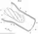
FIG. 1 is a schematic view showing a configuration of a gas turbine in an embodiment according to the present disclosure.
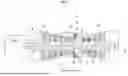
FIG. 2 is a cross-sectional view showing the gas turbine around a combustor in the embodiment according to the present disclosure.
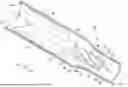
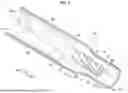
FIG. 3 is a cut out perspective view showing a burner in the embodiment according to the present disclosure.
FIG. 4 is a cross-sectional view showing the burner in the embodiment according to the present disclosure.
FIG. 5 is a cut out perspective view showing a main part of the burner in the embodiment according to the present disclosure.
FIG. 6 is a view for describing a fuel-air ratio distribution in a mixing space in a reference example.
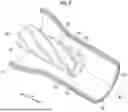
FIG. 7 is a view for describing a fuel-air ratio distribution in a mixing space in the embodiment according to the present disclosure.
FIG. 8 is a cut out perspective view showing a main part of a burner in a first modification example according to the present disclosure.
FIG. 9 is a cut out perspective view showing a main part of a burner in a second modification example according to the present disclosure.
FIG. 10 is a cross-sectional view showing a burner in a third modification example according to the present disclosure.
DESCRIPTION OF EMBODIMENTS
Hereinafter, embodiments of a burner according to the present disclosure, a combustor including the burner, and a gas turbine including the combustor will be described in detail with reference to the drawings, and a modification example of the burner will be further described.
As shown in FIG. 1, a gas turbine in the present embodiment includes a compressor 10 that can compress air A to generate compressed air Acom, a plurality of combustors 20 that can combust a fuel F in the compressed air Acom to generate a combustion gas G, and a turbine 15 that can be driven by the combustion gas G.
The compressor 10 has a compressor rotor 11 that rotates around a rotor axis Ar and a compressor casing 12 that covers the compressor rotor 11. The turbine 15 has a turbine rotor 16 that is rotated around the rotor axis Ar and a turbine casing 17 that covers the turbine rotor 16. In addition, in the following, a direction in which the rotor axis Ar extends is referred to as a rotor axis direction Da, one side of both sides of the rotor axis direction Da is referred to as an axial upstream side Dau, and the other side is referred to as an axial downstream side Dad.
The compressor 10 is disposed on the axial upstream side Dau with respect to the turbine 15. The compressor rotor 11 and the turbine rotor 16 are located on the same rotor axis Ar, and are connected to each other to form a gas turbine rotor 1. For example, a rotor of a generator GEN is connected to the gas turbine rotor 1. The gas turbine further includes an intermediate casing 4 disposed between the compressor casing 12 and the turbine casing 17. The compressed air Acom from the compressor 10 flows into the intermediate casing 4. The plurality of combustors 20 are arranged in a circumferential direction with respect to the rotor axis Ar, and are attached to the intermediate casing 4. The compressor casing 12, the intermediate casing 4, and the turbine casing 17 are connected to each other to form a gas turbine casing 2.
A fuel line is connected to the combustor 20. The combustor 20 can generate the combustion gas G by combusting the fuel F from the fuel line in the compressed air Acom from the compressor 10.
As shown in FIG. 2, the combustor 20 includes a pipe 21 that forms a combustion space Sc in which the fuel F can be combusted, a plurality of burners 30 that eject a premixed gas Gpm in which the fuel F and the compressed air Acom are mixed inside the combustion space Sc, and a burner support frame 25 that supports the plurality of burners 30.
The pipe 21 is sometimes referred to as a transition piece or a combustion pipe. The pipe 21 has a tubular shape around a combustor axis Ac. Here, a direction in which the combustor axis Ac extends is referred to as an extending direction De. In addition, one side of both sides in the extending direction De is referred to as an upstream side Deu, and the other side is referred to as a downstream side Ded. An end of the pipe 21 on the upstream side Deu and an end of the pipe 21 on the downstream side Ded are open. As shown in FIG. 1, an opening on the downstream side Ded of the pipe 21 is formed so that the combustion gas G generated by the combustion of the fuel F can be sent into the turbine casing 17. On the other hand, an opening 22 on the upstream side Deu of the pipe 21 is blocked by the burner support frame 25. The plurality of burners 30 are disposed side by side in a radial direction and the circumferential direction with respect to the combustor axis Ac, and are supported by the burner support frame 25. Therefore, the combustor 20 of the present embodiment is a cluster burner combustor.
Each of the plurality of burners 30 includes a mixing pipe 31, a fuel nozzle 34, and a plurality of nozzle supports 39, as shown in FIGS. 3 and 4.
Each of the mixing pipes 31 for the plurality of burners 30 extends in the extending direction De in which the combustor axis Ac extends, and forms a cylindrical mixing space Sm in which the compressed air Acom and the fuel F are mixed. The mixing pipe 31 has an air inlet 31i through which the compressed air Acom can flow into the mixing space Sm, an ejection port 31o through which a premixed gas Gpm in which the compressed air Acom and the fuel F are mixed can be ejected from the mixing space Sm, and a fuel flow path 31p. The air inlet 31i is formed at an end of the mixing pipe 31 on the upstream side Deu, and the ejection port 31o is formed at an end of the mixing pipe 31 on the downstream side Ded. The mixing space Sm has a reduced area portion 33 in which a cross-sectional area perpendicular to the extending direction De gradually decreases toward the downstream side Ded. The reduced area portion 33 is formed between the air inlet 31i and the ejection port 310 in the extending direction De. The cross-sectional area of a portion on the upstream side Deu of the reduced area portion 33 in the mixing space Sm is larger than the cross-sectional area of a portion on the downstream side Ded of the reduced area portion 33 in the mixing space Sm. The fuel flow path 31p penetrates from an outer peripheral surface of the mixing pipe 31 to an inner peripheral surface 32, and the fuel F can flow through the fuel flow path 31p.
The fuel nozzle 34 is disposed in the mixing space Sm. The fuel nozzle 34 includes a nozzle main body 35 that extends in the extending direction De, and a plurality of protrusion portions 37 that protrude from an outer peripheral surface 36 of the nozzle main body 35 and that are separated from the inner peripheral surface 32 of the mixing pipe 31.
The nozzle main body 35 is disposed on a space central axis Ab which is a central axis of the mixing space Sm. The space central axis Ab extends in the extending direction De. The nozzle main body 35 has a large-diameter portion 35a having a cylindrical shape around the space central axis Ab, a reduced diameter portion 35b having a conical shape around the space central axis Ab, and a small-diameter portion 35c having a cylindrical shape around the space central axis Ab. The large-diameter portion 35a is formed in a portion of the nozzle main body 35 on the upstream side Deu. The reduced diameter portion 35b is connected to an end of the large-diameter portion 35a on the downstream side Ded. An outer diameter of the reduced diameter portion 35b gradually decreases toward the downstream side Ded. The small-diameter portion 35c is connected to an end of the reduced diameter portion 35b on the downstream side Ded and extends to an end of the nozzle main body 35 on the downstream side Ded. An outer diameter of the small-diameter portion 35c is smaller than an outer diameter of the large-diameter portion 35a. The nozzle main body 35 further includes a fuel flow path 35p and a fuel ejection port 350 formed at the end of the nozzle main body 35 on the downstream side Ded. The fuel flow path 35p extends in the extending direction De inside the large-diameter portion 35a, the reduced diameter portion 35b, and the small-diameter portion 35c. The fuel F can flow through the fuel flow path 35p. The fuel ejection port 350 can eject the fuel F that has flowed through the fuel flow path 35p into the mixing space Sm toward the downstream side Ded.
The protrusion portion 37 gradually extends to the downstream side Ded as the protrusion portion 37 extends in the circumferential direction with reference to the nozzle main body 35, and the entire protrusion portion 37 is spirally formed around the nozzle main body 35. In other words, the protrusion portion 37 is formed in a spiral shape as a whole around the space central axis Ab. In FIG. 4, for convenience, the protrusion portion 37 is depicted as linearly extending in the extending direction De in order to easily understand the protrusion amount of the protrusion portion 37. The protrusion portion 37 has an upstream end 37u on the most upstream side Deu in the extending direction De and a downstream end 37d on the most downstream side Ded in the extending direction De. All of the upstream ends 37u of each of the plurality of protrusion portions 37 are located at a boundary between the large-diameter portion 35a and the reduced diameter portion 35b in the extending direction De. All of the downstream ends 37d of each of the plurality of protrusion portions 37 are located at the end of the nozzle main body 35 on the downstream side Ded in the extending direction De. A distance from the space central axis Ab to an outer peripheral surface 38 of the protrusion portion 37 is the same as the outer diameter of the large-diameter portion 35a at any position in the extending direction De. For this reason, the protrusion amount, which is a distance from the outer peripheral surface 36 of the nozzle main body 35 to the outer peripheral surface 38 of the protrusion portion 37, gradually increases toward the downstream side Ded in a portion of the protrusion portion 37 that is formed in the reduced diameter portion 35b of the nozzle main body 35. In addition, the protrusion amount is a maximum protrusion amount pmax at a portion of the protrusion portion 37 that is formed in the small-diameter portion 35c of the nozzle main body 35.
The reduced area portion 33 of the mixing space Sm described above is formed in a region in which the protrusion portion 37 exists in the extending direction De. A portion of the inner peripheral surface 32 of the mixing pipe 31, which is on the downstream side Ded of the reduced area portion 33, faces the outer peripheral surface 36 of the small-diameter portion 35c of the nozzle main body 35 in the radial direction. A distance from a portion of the outer peripheral surface 36 of the nozzle main body 35, which is a portion in which the protrusion portion 37 exists in the extending direction De, to the inner peripheral surface 32 of the mixing pipe 31 is a minimum distance dmin in a distance from the outer peripheral surface 36 of the small-diameter portion 35c of the nozzle main body 35 to a portion of the inner peripheral surface 32 of the mixing pipe 31, which is a portion on the downstream side Ded of the reduced area portion 33. The maximum protrusion amount pmax of the protrusion portion 37 described above is equal to or less than 20% of the minimum distance dmin.
The plurality of nozzle supports 39 connect the outer peripheral surface 36 of the nozzle main body 35 and the inner peripheral surface 32 of the mixing pipe 31 at a position on the downstream side Ded with respect to a region in which the protrusion portion 37 exists in the extending direction De. One nozzle support 39 of the plurality of nozzle supports 39 has a fuel flow path 39p through which the fuel F can flow. The fuel flow path 39p communicates with the fuel flow path 31p of the mixing pipe 31 and the fuel flow path 35p of the nozzle main body 35.
As shown in FIG. 2, a portion of the pipe 21 on the upstream side Deu is connected to an end of the burner support frame 25 on the downstream side Ded, and the opening 22 on the upstream side Deu of the pipe 21 is closed as described above. An end of the burner support frame 25 on the upstream side Deu is connected to the intermediate casing 4. In the extending direction De, the position of the end of the mixing pipe 31 on the upstream side Deu in each of the plurality of burners 30 substantially coincides with the position of the end of the burner support frame 25 on the upstream side Deu. The burner support frame 25 has a fuel flow path 26 through which the fuel F can flow and an air flow path 27 through which the compressed air Acom can flow. The fuel flow path 26 has a main flow path 26m that receives the fuel F from the outside and through which the fuel F can flow, and a plurality of branch flow paths 26b that branch from the main flow path 26m. Each of the plurality of branch flow paths 26b communicates with the fuel flow path 31p of the mixing pipe 31 of any one of the plurality of burners 30. The air flow path 27 is formed so that the compressed air Acom from the compressor 10 can flow into the mixing space Sm for each of the plurality of burners 30.
As shown in FIG. 1, the compressor 10 compresses the air A to generate the compressed air Acom. The compressed air Acom is discharged from the compressor 10 into the intermediate casing 4. As shown in FIG. 2, the compressed air Acom discharged into the intermediate casing 4 flows into the mixing space Sm for each of the plurality of burners 30 through the air flow path 27 of the burner support frame 25. As shown in FIGS. 2 and 4, the fuel F flows into the fuel flow path 35p of the nozzle main body 35 of each of the plurality of burners 30 through the fuel flow path 26p of the burner support frame 25, the fuel flow path 31p of the mixing pipe 31 of each of the plurality of burners 30, and the fuel flow path 39p of the nozzle support 39 of each of the plurality of burners 30. The fuel F that has flowed into the fuel flow path 35p of the nozzle main body 35 is ejected from the fuel ejection port 350 formed at the end on the downstream side Ded of the nozzle main body 35, to the mixing space Sm. The fuel F ejected into the mixing space Sm is mixed with the compressed air Acom in the mixing space Sm, and is ejected into the combustion space Sc of the pipe 21 from the ejection port 310 of the mixing pipe 31 as the premixed gas Gpm. The premixed gas Gpm is combusted in the combustion space Sc to become the combustion gas G. The combustion gas G is sent from the combustor 20 into the turbine casing 17. The combustion gas G rotates the turbine rotor 16 in the process of flowing to the axial downstream side Dad in the turbine casing 17. A rotor of the generator GEN connected to the gas turbine rotor 1 is rotated by rotation of the turbine rotor 16.
As a result, the generator GEN generates electricity.
In the present embodiment, a swirling flow Fs of the compressed air Acom that has flowed into the mixing space Sm is formed by the protrusion portion 37 in the region around the vicinity of the nozzle main body 35 in the virtual plane perpendicular to the extending direction De, which is a region in which protrusion portion 37 exists in the extending direction De, and a region on the downstream side Ded of the protrusion portion 37, as shown in FIG. 5. The protrusion portion 37 is formed in a spiral shape around the space central axis Ab. Therefore, the swirling flow Fs is a flow that swirls around the space central axis Ab. In addition, since the protrusion portion 37 is separated from the inner peripheral surface 32 of the mixing pipe 31, when the compressed air Acom crosses the outer peripheral surface 38 of the protrusion portion 37, a small turbulence Ft1 of the air is generated on the downstream side Ded in the air crossing direction on the outer peripheral surface 38. Further, a small turbulence Ft2 of the air is also generated on the downstream side Ded of the downstream end 37d of the protrusion portion 37.
In a case in which the spiral-shaped protrusion portion 37 is not provided around the nozzle main body 35, the mixing of the compressed air Acom and the fuel F ejected from the nozzle main body 35 is not promoted, and in a downstream main body surrounding region Ra (shown in FIGS. 4 and 7) which is a region around the vicinity of the nozzle main body 35 in the virtual plane perpendicular to the extending direction De, a region in which a fuel-air ratio (fuel amount/air amount) is high is formed as shown in FIG. 6. In FIG. 6, and FIG. 7 to be described later, the color is depicted to be darker as the fuel-air ratio increases.
On the other hand, in the present embodiment, as described above, in the downstream main body surrounding region Ra, which is a region on the downstream side Ded of the protrusion portion 37 and which is a region around the vicinity of the nozzle main body 35 in the virtual plane perpendicular to the extending direction De. the swirling flow Fs as the main air flow is formed, and small turbulences Ft1 and Ft2 are formed. For this reason, in the present embodiment, in the downstream main body surrounding region Ra, the mixing of the compressed air Acom and the fuel F ejected from the nozzle main body 35 is promoted. In particular, in the present embodiment, the protrusion portion 37 is formed in a region including the end on the downstream side Ded of the nozzle main body 35. Therefore, in the present embodiment, the influence of the swirling flow Fs and the turbulences Ft1 and Ft2 of the compressed air Acom formed by the protrusion portion 37 can be more strongly applied to the fuel F ejected from the end of the nozzle main body 35 on the downstream side Ded than in a case in which the downstream end 37d of the protrusion portion 37 is formed on the upstream side Deu from the end of the nozzle main body 35 on the downstream side Ded. Accordingly, in the present aspect, in the downstream main body surrounding region Ra, the compressed air Acom and the fuel F can be effectively mixed. Therefore, in the present embodiment, as shown in FIG. 7, it is possible to suppress the occurrence of a region having a high fuel-air ratio (fuel amount/air amount) in the downstream main body surrounding region Ra, and to suppress the generation of NOx.
In addition, in the present embodiment, the protrusion portion 37 is separated from the inner peripheral surface 32 of the mixing pipe 31. In particular, as described above, the maximum protrusion amount pmax of the protrusion portion 37 from the outer peripheral surface 36 of the nozzle main body 35 is equal to or less than 20% of the minimum distance dmin from the outer peripheral surface 36 of the small-diameter portion 35c of the nozzle main body 35 to the inner peripheral surface 32 of the mixing pipe 31. Therefore, in the present embodiment, it is possible to reduce the area of the region in which a circumferential component flow rate Ve (FIG. 7) of the swirling flow Fs is a first flow rate or higher in the downstream main body surrounding region Ra described above in the virtual plane perpendicular to the extending direction De. On the other hand, in the present embodiment, in the region on the downstream side Ded of the protrusion portion 37, the area of the region in which the circumferential component flow rate Ve of the swirling flow Fs is equal to or less than a second flow rate which is slower than the first flow rate, can be increased in an inner peripheral surface vicinity region Rb (shown in FIGS. 4 and 7) of the mixing pipe 31 in the virtual plane perpendicular to the extending direction De. Therefore, in the present aspect, the mixing of the fuel F with the compressed air Acom flowing along the inner peripheral surface 32 of the mixing pipe 31 can be suppressed in the inner peripheral surface vicinity region Rb in which the gas flow rate is slow, and a reverse fire, which is a flame transmitted into the mixing space Sm, can be suppressed.
In the present embodiment, an air flow having a directional component toward a center of the mixing pipe 31 is generated in the region along the inner peripheral surface 32 of the mixing pipe 31 in the reduced area portion 33. Due to this air flow, in the present embodiment, the swirling flow Fs formed by the protrusion portion 37 is pushed to a center side of the mixing pipe 31. Therefore, in the present embodiment, in the downstream main body surrounding region Ra described above in the virtual plane perpendicular to the extending direction De, a region in which the circumferential component flow rate Vc of the swirling flow Fs is equal to or higher than the first flow rate is close to the center side of the mixing pipe 31. As a result, in the present embodiment, it is possible to reduce the area of the region in which the circumferential component flow rate Vc of the swirling flow Fs is equal to or higher than the first flow rate. Further, the cross-sectional area of the mixing space Sm on the downstream side Ded of the reduced area portion 33 is smaller than the cross-sectional area of the mixing space Sm on the upstream side Deu of the reduced area portion 33. For this reason, in the present embodiment, the gas flow rate in the mixing space Sm on the downstream side Ded of the reduced area portion 33 in the extending direction De is higher than the gas flow rate in a case in which the reduced area portion 33 does not exist. Therefore, in the present embodiment, the reverse fire which is the flame transmitted into the mixing space Sm can be effectively suppressed.
The air that has flowed into the mixing space Sm is subjected to a pressure loss by the nozzle support 39. Moreover, when a part of the mixing space Sm is occupied by the nozzle support 39, a region in which the compressed air Acom flows in the mixing space Sm becomes narrow, the flow rate of the compressed air Acom increases, and the pressure loss of the air increases due to the nozzle support 39. Therefore, in the present embodiment, in order to suppress the pressure loss of the compressed air Acom due to the nozzle support 39, the nozzle support 39 is disposed in a region in which the cross-sectional area of the mixing space Sm is larger than the cross-sectional area of the reduced area portion 33 on the upstream side Deu.
The protrusion portion 37 of the present embodiment does not exist on a radial outer side with respect to the space central axis Ab from the large-diameter portion 35a. For this reason, in the present embodiment, it is possible to suppress a pressure loss of the compressed air Acom due to a collision of the compressed air Acom flowing along the large-diameter portion 35a of the nozzle main body 35 with the upstream end 37u of the protrusion portion 37.
Modification Example
In the above-described embodiment, the maximum protrusion amount pmax of the protrusion portion 37 is equal to or less than 20% of the minimum distance dmin from the outer peripheral surface 36 of the small-diameter portion 35c of the nozzle main body 35 to the inner peripheral surface 32 of the mixing pipe 31. However, depending on the flow rate of the compressed air Acom flowing inside the mixing space Sm in the extending direction De, the maximum protrusion amount pmax of the protrusion portion 37 may be larger than 20% of the minimum distance dmin from the outer peripheral surface 36 of the small-diameter portion 35c of the nozzle main body 35 to the inner peripheral surface 32 of the mixing pipe 31 and may be equal to or less than half of the minimum distance dmin.
In the above-described embodiment, the protrusion portion 37 is formed in a predetermined range from the end on the downstream side Ded of the nozzle main body 35 toward the upstream side Deu. However, as shown in FIG. 8, the protrusion portion 37a may be formed in a predetermined range from a position on the upstream side Deu with respect to the end on the downstream side Ded of the nozzle main body 35 toward the upstream side Deu.
In the above-described embodiment, the protrusion portion 37 is not formed in the region including the end on the upstream side Deu of the nozzle main body 35. However, the protrusion portion may be formed in a region including the end on the upstream side Deu of the nozzle main body 35.
In the above-described embodiment, one protrusion portion 37 is formed along one virtual line having a spiral shape around the space central axis Ab. However, as shown in FIG. 9, a plurality of protrusion portions 37b and 37c may be formed along one virtual line having a spiral shape around the space central axis Ab.
In the above-described embodiment, the entire nozzle main body 35 is accommodated in the mixing space Sm. However, as shown in FIG. 10, an end of the nozzle main body 35 on the upstream side Deu may protrude to the upstream side Deu from an end of the mixing space Sm on the upstream side Deu. Even in this case, as described above, the protrusion portion 37 may be formed in a region including the end on the upstream side Deu of the nozzle main body 35. That is, a part of the protrusion portion 37 may be formed outside the mixing space Sm.
The combustor 20 in the above-described embodiment is a cluster burner combustor in which a plurality of burners 30 are disposed in the circumferential direction and the radial direction with respect to the combustor axis Ac. However, the burner structure of the present disclosure may be applied to a premixing burner in a normal combustor in which a plurality of premixing burners are not disposed in the radial direction with respect to the combustor axis Ac.
In addition, the present disclosure is not limited to the above-described embodiment and the modification example. Various additions, modifications, substitutions, partial deletions, and the like can be made without departing from the conceptual idea and gist of the present invention derived from the contents defined in the claims and equivalents thereof.
Supplementary Note
The burner in the above-described embodiment is understood as follows, for example.
-
- (1) A burner according to a first aspect includes:
- a mixing pipe 31 that extends in a predetermined extending direction De and in which a mixing space Sm for mixing air Acom and fuel F is formed; and a fuel nozzle 34 that extends in the extending direction De and of which at least a part is disposed in the mixing space Sm. The mixing pipe 31 has an air inlet 31i through which the air Acom can flow into the mixing space Sm, and an ejection port 310 through which a premixed gas Gpm in which the air Acom and the fuel F are mixed can be ejected from the mixing space Sm. The ejection port 310 is formed at an end of the mixing pipe 31 on a downstream side Ded, out of an upstream side Deu which is one side in the extending direction De and the downstream side Ded which is the other side of the extending direction De. The fuel nozzle 34 has a nozzle main body 35 that extends in the extending direction De, and protrusion portions 37,37a, 37b, and 37c that protrude from an outer peripheral surface 36 of the nozzle main body 35 and are separated from an inner peripheral surface 32 of the mixing pipe 31. The nozzle main body 35 has a fuel ejection port 350 that can eject the fuel F into the mixing space Sm from a position, which is on the downstream side Ded of the air inlet 31i and on the upstream side Deu of the ejection port 310. The protrusion portions 37,37a, 37b, and 37c gradually extend to the downstream side Ded as the protrusion portions 37,37a, 37b, and 37c extend in a circumferential direction with reference to the nozzle main body 35, and an entire portion of the protrusion portions 37,37a, 37b, and 37c is formed in a spiral shape around the nozzle main body 35.
In the present aspect, the swirling flow Fs of the air Acom that has flowed into the mixing space Sm can be formed by the protrusion portions 37, 37a, 37b, and 37c in the region around the vicinity of the nozzle main body 35 in the virtual plane perpendicular to the extending direction De, which is a region in which the protrusion portions 37, 37a, 37b, and 37c exist in the extending direction De and a region on the downstream side Ded of the protrusion portions 37, 37a, 37b, and 37c. In addition, since the protrusion portions 37, 37a, 37b, and 37c are separated from the inner peripheral surface 32 of the mixing pipe 31, when the air Acom crosses the outer peripheral surface 38 of the protrusion portions 37, 37a, 37b, and 37c, a small turbulence Ft1 of the air Acom is generated on the downstream side Ded in the air crossing direction on the outer peripheral surface 38. Further, a small turbulence Ft1 of the air Acom also occurs on the downstream side Ded of the downstream end 37d of the protrusion portions 37, 37a, 37b, and 37c. As described above, in the present aspect, the swirling flow Fs as the main air flow is formed in the downstream main body surrounding region Ra, which is a region on the downstream side Ded of the protrusion portions 37, 37a, 37b, and 37c and a region in the vicinity of the nozzle main body 35 in the virtual plane perpendicular to the extending direction De, and small turbulences Ft1 and Ft2 are formed. Therefore, in the present aspect, in the downstream main body surrounding region Ra, the mixing of the air Acom and the fuel F ejected from the nozzle main body 35 is promoted. Therefore, in the present aspect, the generation of a region having a high fuel-air ratio (fuel amount/air amount) in the mixing space Sm can be suppressed, and the generation of NOx can be suppressed.
In addition, in the present aspect, since the protrusion portions 37, 37a, 37b, and 37c are separated from the inner peripheral surface 32 of the mixing pipe 31, the influence of the swirling flow Fs in the inner peripheral surface vicinity region Rb of the mixing pipe 31, which is the region on the downstream side Ded of the protrusion portions 37, 37a, 37b, and 37c, can be suppressed in the virtual plane perpendicular to the extending direction De. Therefore, in the present aspect, the mixing of the air Acom and the fuel F in the inner peripheral surface vicinity region Rb is suppressed. Therefore, in the present aspect, the fuel-air ratio (fuel amount/air amount) can be kept low in the inner peripheral surface vicinity region Rb in which the gas flow rate is low, and a reverse fire, which is a flame transmitted into the mixing space Sm, can be suppressed.
-
- (2) In a bumer according to a second aspect,
- in the burner 30 according to the first aspect, a maximum protrusion amount pmax of the protrusion portions 37, 37a, 37b, and 37c from the outer peripheral surfaces 36, 38 of the nozzle main body 35 is equal to or less than half of a minimum distance dmin from a portion, which is a part of the outer peripheral surface 36 of the nozzle main body 35 and in which the protrusion portions 37, 37a, 37b, and 37c exist in the extending direction De, to the inner peripheral surface 32 of the mixing pipe 31.
In the present aspect, it is possible to reduce the area of the region in which the circumferential component flow rate of the swirling flow Fs is equal to or higher than the first flow rate, in the downstream main body surrounding region Ra described above in the virtual plane perpendicular to the extending direction De. On the other hand, in the present aspect, it is possible to increase the area of the region in which the circumferential component flow rate of the swirling flow Fs is equal to or lower than the second flow rate, which is slower than the first flow rate, in the inner peripheral surface vicinity region Rb described above in the virtual plane perpendicular to the extending direction De. Therefore, in the present aspect, the mixing of the fuel F with the air Acom flowing along the inner peripheral surface 32 of the mixing pipe 31 can be suppressed in the inner peripheral surface vicinity region Rb in which the gas flow rate is slow, and a reverse fire, which is a flame transmitted into the mixing space Sm, can be suppressed.
-
- (3) In a burner according to a third aspect,
- in the burner 30 according to the first aspect or the second aspect, a maximum protrusion amount pmax of the protrusion portions 37, 37a, 37b, and 37c from the outer peripheral surfaces 36, 38 of the nozzle main body 35 is equal to or less than 20% of a minimum distance dmin from a portion, which is a part of the outer peripheral surfaces 36, 38 of the nozzle main body 35 and in which the protrusion portions 37, 37a, 37b, and 37c exist in the extending direction De, to the inner peripheral surface 32 of the mixing pipe 31.
In the present aspect, it is possible to reduce the area of the region in which the circumferential component flow rate of the swirling flow Fs is equal to or higher than the first flow rate, in the downstream main body surrounding region Ra described above in the virtual plane perpendicular to the extending direction De. On the other hand, in the present aspect, it is possible to increase the area of the region in which the circumferential component flow rate of the swirling flow Fs is equal to or lower than the second flow rate, which is slower than the first flow rate, in the inner peripheral surface vicinity region Rb described above in the virtual plane perpendicular to the extending direction De. Therefore, in the present aspect, the mixing of the fuel F with the air Acom flowing along the inner peripheral surface 32 of the mixing pipe 31 can be suppressed in the inner peripheral surface vicinity region Rb in which the gas flow rate is slow, and a reverse fire, which is a flame transmitted into the mixing space Sm, can be suppressed.
-
- (4) In a burner according to a fourth aspect,
- in the burner 30 according to any one of the first aspect to third aspect, the fuel ejection port 350 is formed at an end of the nozzle main body 35 on the downstream side Ded. The protrusion portions 37, 37c are formed in a predetermined range on an outer peripheral surface 36 of the nozzle main body 35 from the end of the nozzle main body 35 on the downstream side Ded toward the upstream side Deu of the nozzle main body 35.
In the present aspect, the protrusion portions 37, 37c are formed in a region including the end of the nozzle main body 35 on the downstream side Ded. Therefore, in the present aspect, the influence of the swirling flow Fs and the turbulences Ft1 and Ft2 of the air Acom formed by the protrusion portions 37, 37c can be more strongly applied to the fuel F ejected from the end of the nozzle main body 35 on the downstream side Ded than in a case in which the downstream end 37d of the protrusion portions 37, 37c is formed on the upstream side Deu from the end of the nozzle main body 35 on the downstream side Ded. Therefore, in the present aspect, the air Acom and the fuel F can be effectively mixed in the above-described downstream main body surrounding region Ra.
-
- (5) In a burner according to a fifth aspect,
- in the burner 30 according to any one of the first aspect to the fourth aspect, the protrusion portions 37, 37a, 37b and 37c are formed only in the mixing space Sm.
- (6) In a burner according to a sixth aspect,
- in the burner 30 according to the fifth aspect, the mixing space Sm has a reduced area portion 33 of which a cross-sectional area perpendicular to the extending direction De gradually decreases toward the downstream side Ded. The reduced area portion 33 is formed in a region in which the protrusion portions 37, 37a, 37b, and 37c exist in the extending direction De.
In the present aspect, an air flow having a directional component toward the center of the mixing pipe 31 is generated in the region along the inner peripheral surface 32 of the mixing pipe 31 in the reduced area portion 33. Due to this air flow, the swirling flow Fs formed by the protrusion portions 37, 37a, 37b, and 37c is pushed to the center side of the mixing pipe 31. For this reason, in the present aspect, in the downstream main body surrounding region Ra described above in the virtual plane perpendicular to the extending direction De, a region in which the circumferential component flow rate Vc of the swirling flow Fs is equal to or higher than the first flow rate is close to the center side of the mixing pipe 31. As a result, in the present aspect, it is possible to reduce the area of the region in which the circumferential component flow rate Ve is equal to or higher than the first flow rate. Further, the cross-sectional area of the mixing space Sm on the downstream side Ded of the reduced area portion 33 is smaller than the cross-sectional area of the mixing space Sm on the upstream side Deu of the reduced area portion 33. Therefore, in the present aspect, the gas flow rate in the mixing space Sm on the downstream side Ded of the reduced area portion 33 in the extending direction De is higher than the gas flow rate in a case in which the reduced area portion 33 is not provided. Therefore, in the present aspect, the reverse fire which is the flame transmitted into the mixing space Sm can be effectively suppressed.
-
- (7) In a bumer according to a seventh aspect,
- in the burner 30 according to the sixth aspect further includes the nozzle support 39 configured to support the fuel nozzle 34 inside the mixing space Sm. The nozzle support 39 connects the outer peripheral surfaces 36, 38 of the nozzle main body 35 and the inner peripheral surface 32 of the mixing pipe 31 at a position on the upstream side Deu of a region in which the reduced area portion 33 is formed in the extending direction De.
The air Acom that has flowed into the mixing space Sm is subjected to a pressure loss by the nozzle support 39. Moreover, when a part of the mixing space Sm is occupied by the nozzle support 39, a region in which the air Acom flows in the mixing space Sm becomes narrow, the flow rate of the air Acom increases, and the pressure loss of the air Acom increases due to the nozzle support 39. Therefore, in the present aspect, in order to suppress the pressure loss of the air Acom caused by the nozzle support 39, the nozzle support 39 is disposed in a region in which the cross-sectional area of the mixing space Sm is larger on the upstream side Deu than in the reduced area portion 33.
-
- (8) In a burner according to an eighth aspect,
- in the burner 30 according to any one of the first aspect to the seventh aspect, the mixing space Sm is a space having a cylindrical shape. The nozzle main body 35 is disposed on a space central axis Ab of the mixing space Sm.
- (9) In a burner according to a ninth aspect,
- in the burner 30 according to the eighth aspect, the nozzle main body 35 has a large-diameter portion 35a having a cylindrical shape around the space central axis Ab, a reduced diameter portion 35b having a conical shape around the space central axis Ab, and a small-diameter portion 35c having a cylindrical shape around the space central axis Ab. The reduced diameter portion 35b is connected to an end of the large-diameter portion 35a on the downstream side Ded, and an outer diameter of the reduced diameter portion 35b gradually decreases toward the downstream side Ded. The small-diameter portion 35c is connected to an end of the reduced diameter portion 35b on the downstream side Ded. An upstream end 37u of the protrusion portions 37, 37a, 37b, and 37c is located at a boundary between the large-diameter portion 35a and the reduced diameter portion 35b in the extending direction De. A downstream end 37d of the protrusion portions 37, 37a, 37b, and 37c is located at an end of the small-diameter portion 35c on the downstream side Ded. A distance from the space central axis Ab to an outer peripheral surface 38 of the protrusion portions 37, 37a, 37b and 37c is equal to or smaller than an outer diameter of the large-diameter portion 35a at any position in the extending direction De.
The protrusion portions 37, 37a, 37b, and 37c according to the present aspect do not exist on the radial outer side with respect to the space central axis Ab with respect to the large-diameter portion 35a. For this reason, in the present aspect, it is possible to suppress a pressure loss of the air Acom due to a collision of the air Acom flowing along the large-diameter portion 35a of the nozzle main body 35 with the upstream end 37u of the protrusion portions 37, 37a, 37b, and 37c.
For example, the combustor in the above embodiment is understood as follows.
-
- (10) A combustor according to a tenth aspect includes:
- the burner 30 according to any one of the first aspect to the ninth aspect; and a pipe 21 in which the premixed gas Gpm ejected from the ejection port 310 of the burner 30 can be combusted.
For example, the cluster burner combustor in the above embodiment is understood as follows.
-
- (11) A cluster burner combustor according to an eleventh aspect includes:
- a plurality of the burners 30 according to any one of the first aspect to the ninth aspect; and a pipe 21 in which the premixed gas Gpm ejected from the ejection port 310 of each of the plurality of burners 30 can be combusted. The extending direction De of each of the plurality of burners 30 is the same direction as each other. Positions of the ejection ports 310 of the plurality of burners 30 in the extending direction De are aligned with each other.
For example, the gas turbine in the above-described embodiment is understood as follows.
-
- (12) A gas turbine according to a twelfth aspect includes:
- the combustor according to the tenth aspect; a compressor 10 configured to compress air A to generate compressed air Acom and supply the compressed air Acom to the burner 30; and a turbine 15 configured to be driven by a combustion gas G generated by the combustion of the premixed gas Gpm in the pipe 21 of the combustor
- (13) A gas turbine according to a thirteenth aspect includes:
- the cluster burner combustor according to the eleventh aspect; a compressor 10 configured to compress air A to generate compressed air Acom and supply the compressed air Acom to the plurality of burners 30; and a turbine 15 configured to be driven by a combustion gas G generated by the combustion of the premixed gas Gpm in the pipe of the cluster burner combustor.
INDUSTRIAL APPLICABILITY
In one aspect of the present disclosure, it is possible to suppress the generation of NOx while suppressing the reverse fire.
REFERENCE SIGNS LIST
-
- 1: gas turbine rotor
- 2: gas turbine casing
- 4: intermediate casing
- 10: compressor
- 11: compressor rotor
- 12: compressor casing
- 15: turbine
- 16: turbine rotor
- 17: turbine casing
- 20: combustor
- 21: pipe
- 22: opening on upstream side
- 25: burner support frame
- 26: fuel flow path
- 26m: main flow path
- 26b: branch flow path
- 27: air flow path
- 30: burner
- 31: mixing pipe
- 31i: air inlet
- 31o: ejection port
- 31p: fuel flow path
- 32: inner peripheral surface
- 33: reduced area portion
- 34: fuel nozzle
- 35: nozzle main body
- 35a: large-diameter portion
- 35b: reduced diameter portion
- 35c: small-diameter portion
- 35o: fuel ejection port
- 35p: fuel flow path
- 36: outer peripheral surface
- 37, 37a, 37b, 37c: protrusion portion
- 37u: upstream end
- 37d: downstream end
- 38: outer peripheral surface
- 39: nozzle support
- 39p: fuel flow path
- A: air
- Acom: compressed air
- F: fuel
- G: combustion gas
- Gpm: premixed gas
- Ar: rotor axis
- Ac: combustor axis
- Ab: space central axis
- Da: rotor axis direction
- Dau: axial upstream side
- Dad: axial downstream side
- De: extending direction
- Deu: upstream side
- Ded: downstream side
- Sc: combustion space
- Sm: mixing space
- Ra: downstream main body surrounding region
- Rb: inner peripheral surface vicinity region
- Fs: swirling flow
- Ft1, Ft2: turbulence
Claims
1. A burner comprising:
a mixing pipe that extends in a predetermined extending direction and in which a mixing space for mixing air and fuel is formed; and
a fuel nozzle that extends in the extending direction and of which at least a part is disposed in the mixing space,
wherein the mixing pipe has an air inlet through which the air can flow into the mixing space, and an ejection port through which a premixed gas in which the air and the fuel are mixed can be ejected from the mixing space,
the ejection port is formed at an end of the mixing pipe on a downstream side, out of an upstream side which is one side in the extending direction and the downstream side which is the other side of the extending direction,
the fuel nozzle has a nozzle main body that extends in the extending direction, and a protrusion portion that protrudes from an outer peripheral surface of the nozzle main body and is separated from an inner peripheral surface of the mixing pipe,
the nozzle main body has a fuel ejection port that can eject the fuel into the mixing space from a position which is on the downstream side of the air inlet and on the upstream side of the ejection port, and
the protrusion portion gradually extends to the downstream side as the protrusion portion extends in a circumferential direction with reference to the nozzle main body, and an entire portion of the protrusion portion is formed in a spiral shape around the nozzle main body.
2. The burner according to claim 1,
wherein a maximum protrusion amount of the protrusion portion from the outer peripheral surface of the nozzle main body is equal to or less than a half of a minimum distance from a portion, which is a part of the outer peripheral surface of the nozzle main body and in which the protrusion portion exists in the extending direction, to the inner peripheral surface of the mixing pipe.
3. The burner according to claim 1,
wherein a maximum protrusion amount of the protrusion portion from the outer peripheral surface of the nozzle main body is equal to or less than 20% of a minimum distance from a portion, which is a part of the outer peripheral surface of the nozzle main body and in which the protrusion portion exists in the extending direction, to the inner peripheral surface of the mixing pipe.
4. The burner according to claim 1,
wherein the fuel ejection port is formed at an end of the nozzle main body on the downstream side, and
the protrusion portion is formed in a predetermined range on an outer peripheral surface of the nozzle main body from the end of the nozzle main body on the downstream side toward the upstream side of the nozzle main body.
5. The burner according to claim 4,
wherein the protrusion portion is formed only in the mixing space.
6. The burner according to claim 5,
wherein the mixing space has a reduced area portion of which a cross-sectional area perpendicular to the extending direction gradually decreases toward the downstream side, and
the reduced area portion is formed in a region in which the protrusion portion exists in the extending direction.
7. The burner according to claim 6, further comprising:
a nozzle support configured to support the fuel nozzle inside the mixing space,
wherein the nozzle support connects the outer peripheral surface of the nozzle main body and the inner peripheral surface of the mixing pipe at a position on the upstream side of a region in which the reduced area portion is formed in the extending direction.
8. The burner according to claim 1,
wherein the mixing space is a space having a cylindrical shape, and
the nozzle main body is disposed on a space central axis of the mixing space.
9. The burner according to claim 8,
wherein the nozzle main body has a large-diameter portion having a cylindrical shape around the space central axis, a reduced diameter portion having a conical shape around the space central axis, and a small-diameter portion having a cylindrical shape around the space central axis,
the reduced diameter portion is connected to an end of the large-diameter portion on the downstream side, and an outer diameter of the reduced diameter portion gradually decreases toward the downstream side,
the small-diameter portion is connected to an end of the reduced diameter portion on the downstream side,
an upstream end of the protrusion portion is located at a boundary between the large-diameter portion and the reduced diameter portion in the extending direction,
a downstream end of the protrusion portion is located at an end of the small-diameter portion on the downstream side, and
a distance from the space central axis to an outer peripheral surface of the protrusion portion is equal to or smaller than an outer diameter of the large-diameter portion at any position in the extending direction.
10. A combustor comprising:
the burner according to claim 1; and
a pipe in which the premixed gas ejected from the ejection port of the burner can be combusted.
11. A cluster burner combustor comprising:
a plurality of the burners according to claim 1; and
a pipe in which the premixed gas ejected from of the ejection port of each of the plurality of burners can be combusted,
wherein the extending direction of each of the plurality of burners is the same direction as each other, and
positions of the ejection ports of the plurality of burners in the extending direction are aligned with each other.
12. A gas turbine comprising:
the combustor according to claim 10;
a compressor configured to compress air to generate compressed air and supply the compressed air to the burner; and
a turbine configured to be driven by a combustion gas generated by the combustion of the premixed gas in the pipe of the combustor.
13. A gas turbine comprising:
the cluster burner combustor according to claim 11;
a compressor configured to compress air to generate compressed air and supply the compressed air to the plurality of burners; and
a turbine configured to be driven by a combustion gas generated by the combustion of the premixed gas in the pipe of the cluster burner combustor.
Images & Drawings included:


Sources:
- United States Patent and Trademark Office - verify current appl. status at the USPTO↗
Similar patent applications:
Recent applications in this class:
- » 20260092706 2026-04-02
Turbine Engine and Fuel Nozzle Assembly Therefor - » 20260092705 2026-04-02
GAS TURBINE ENGINE AND FUEL INJECTOR ASSEMBLY THEREFOR - » 20260085837 2026-03-26
COAXIALLY STAGED BURNER FOR LOW-EMISSION COMBUSTION CHAMBER OF DUAL-FUEL GAS TURBINE UTILIZING GASEOUS AND LIQUID FUELS - » 20260078905 2026-03-19
TURBINE ENGINE WITH COMBUSTION SECTION AND FUEL PASSAGE THAT SUPPLIES HYDROGEN-CONTAINING FUEL TO COMBUSTION SECTION - » 20260055894 2026-02-26
COMBUSTOR WITH DISTRIBUTED AIR AND FUEL MIXING - » 20260049719 2026-02-19
Engine Fuel Nozzle with Coaxial Fuel and Air Flow - » 20260043546 2026-02-12
PERFORATED PLATE FUEL DISTRIBUTOR WITH SIMIPLIFIED SWIRLER - » 20260036300 2026-02-05
AIRCRAFT ENGINE COMBUSTOR - » 20260022839 2026-01-22
GAS TURBINE ENGINE AND FUEL NOZZLE ASSEMBLY THEREFOR - » 20260022838 2026-01-22
GAS TURBINE ENGINE AND FUEL NOZZLE ASSEMBLY THEREFOR