CONCEALMENT INSERT FOR A HOLSTER
US20260104232A1
2026-04-16
19/342,755
2025-09-29
Smart Summary: A concealment insert is designed to fit inside a holster. It has a top edge, bottom edge, and two lateral edges that match the shape of the holster. One side of the insert is sloped to blend in with the holster's exterior. The other side is flat and faces the opposite direction. This insert helps make the holster less noticeable when carrying a weapon. 🚀 TL;DR
Abstract:
A concealment insert for use with a holster is disclosed. The concealment insert includes a top edge, a bottom edge, a first lateral edge, a second lateral edge, a first side, and a second side. The first lateral edge and the second lateral edge are shaped to correspond to respective contours of exterior surfaces of the holster adjacent the attachment area. The first side is a sloped surface shaped to continue a contour of adjacent portions of an exterior side of the holster, and the second side is positioned opposite the first side.
Applicant:
Interested in similar patents?
Get notified when new applications in this technology area are published.
Classification:
F41C33/048 » CPC main
Means for wearing or carrying smallarms; Holsters, i.e. cases for pistols having means for being carried or worn, e.g. at the belt or under the arm; Special attachments therefor for concealed carrying of a small arm
F41C33/04 IPC
Means for wearing or carrying smallarms; Holsters, i.e. cases for pistols having means for being carried or worn, e.g. at the belt or under the arm Special attachments therefor
Description
CROSS-REFERENCE TO RELATED APPLICATION(S)
This application claims the benefit of U.S. Provisional Application Ser. No. 63/705,593, filed on Oct. 10, 2024, the entirety of which is incorporated herein by reference.
TECHNICAL FIELD
This disclosure relates to implementations of a concealment insert for use with a holster.
BACKGROUND
Handgun holsters are routinely used to carry handguns in a secure and accessible manner. Many holsters are design for inside-the-waistband (IWB) carry, in which the holster is positioned inside the waistband of a wearer's clothing. With IWB holsters, one side of the holster typically rests directly against the wearer's body. To reduce printing of the handgun through clothing, some holsters include concealment wings or other attachments that apply pressure to rotate the handgun grip inward, toward the body. Holsters that incorporate such attachments often include recessed attachment areas. While these attachment areas allow secure mounting of concealment wings or similar hardware, they can leave discontinuities or gaps on the body-side of the holster when the attachment area is not occupied. The discontinuities may cause discomfort.
SUMMARY
It is to be understood that this summary is not an extensive overview of the disclosure. This summary is exemplary and not restrictive, and it is intended neither to identify key or critical elements of the disclosure nor delineate the scope thereof. The sole purpose of this summary is to explain and exemplify certain concepts of the disclosure as an introduction to the following complete and extensive detailed description.
Disclosed are implementations of a concealment insert for use with a holster.
In one example implementation, a concealment insert includes a top edge, a bottom edge, a first lateral edge, a second lateral edge, a first side, and a second side. The first lateral edge and the second lateral edge are shaped to correspond to respective contours of exterior surfaces of the holster adjacent the attachment area. The first side is a sloped surface shaped to continue a contour of adjacent portions of an exterior side of the holster, and the second side is positioned opposite the first side.
In another example implementation, a holster system includes a holster having a cavity for receiving a handgun and a concealment insert coupled to an attachment area of the holster. The attachment area is defined by adjacent exterior surfaces of the holster, and the concealment insert is configured to substantially fill the attachment area.
In yet another example implementation, a holster system includes a holster having a cavity for receiving a handgun and a concealment insert coupled to an attachment area of the holster. The attachment area is defined between a trigger-guard retention surface, an external surface of the cavity, a contoured edge of the holster, and a rear edge of the holster. The concealment insert is configured to substantially fill the attachment area and to continue a contour of an exterior side of the holster adjacent the attachment area.
Any aspect of any implementation, in combination with any one or more aspects of any other implementation(s).
Any one or more of the features disclosed herein.
Any one or more of the features as substantially disclosed herein.
Any one or more of the features as substantially disclosed herein, in combination with any one or more other features as substantially disclosed herein.
Any one of the aspects, features, or implementations, in combination with any one or more other aspects, features, or implementations.
Use of any one or more of the aspects or features disclosed herein.
It should be appreciated that any feature described herein can be claimed in combination with any other feature(s) described herein, regardless of whether the features originate from the same described implementation.
The details of one or more aspects of the disclosure are set forth in the accompanying drawings and the description below. Other features, objects, and advantages of the techniques described in this disclosure will be apparent from the description and drawings, and from the claims.
Numerous additional features and advantages of the present disclosure will become apparent to those skilled in the art upon consideration of the implementation descriptions provided below.
Additional features and advantages are described herein and will be apparent from the following description and figures.
BRIEF DESCRIPTION OF THE DRAWINGS
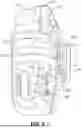
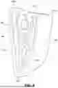
FIG. 1 is a perspective view of a concealment insert, shown coupled to a holster, in accordance with the principles of the present disclosure.
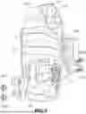
FIG. 2 is an exploded view of the concealment insert and holster shown in FIG. 1.
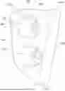
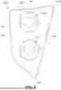
FIG. 3 is a perspective view of the concealment insert shown in FIG. 1.
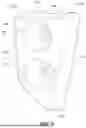
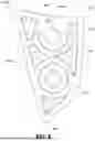
FIG. 4 is another perspective view of the concealment insert shown in FIG. 3.
FIG. 5 is a front elevational view of the concealment insert shown in FIG. 3.
FIG. 6 is a rear elevational view of the concealment insert shown in FIG. 3.
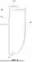
FIG. 7 is a side elevational view of the concealment insert shown in FIG. 3.
FIG. 8 is another side elevational view of the concealment insert shown in FIG. 3.
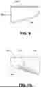
FIG. 9 is a top plan view of the concealment insert shown in FIG. 3.
FIG. 10 is a bottom plan view of the concealment insert shown in FIG. 3.
Like reference numerals refer to corresponding parts throughout the several views of the drawings.
DETAILED DESCRIPTION
FIG. 1-10 illustrate a concealment insert 100 according to the principles of the present disclosure. As shown in FIG. 1, the concealment insert 100 is configured for attachment to the body-side of the holster 102. As used herein, the term “body-side” refers to the side of the holster 102 in direct contact with the wearer. The concealment insert 100 is configured to substantially fill the attachment area 120 of the holster 102, thereby improving overall comfort for the wearer.
As shown in FIGS. 1 and 2, the example holster 102 is formed from two clamshell-type halves 110, 112 that are secured together to create a cavity 114 for a handgun. Each half 110, 112 of the holster 102 includes an exterior side 116, 118 that defines an attachment area 120 for a concealment wing, such as a ModWing 108. Each attachment area 120 is a depression positioned between a trigger-guard retention surface 122, an external surface 124 of the gun cavity shaped to accommodate the dustcover of a handgun frame, a contoured edge 126 of the integral concealment wedge, and a portion 128 of the rear edge of the holster 102. Both attachment areas 120 of the holster 102 share a pair of openings 130, which are spaced and positioned to allow the use of Chicago screws 132 to attach the concealment insert 100 to the body-side attachment area 120 and, if desired, a concealment wing 108, to the other attachment area 120 (see, e.g., FIG. 1).
As shown in FIG. 1, the concealment insert 100 is configured to substantially fill the attachment area 120 on one side of the holster 102 and, in some implementations, is shaped to continue the contour of adjacent exterior surfaces.
The concealment insert 100 includes a top edge 140, a bottom edge 142, a first lateral edge 144, a second lateral edge 146, a first side 148, and a second side 150. The first and second lateral edges 144, 146 are shaped to substantially match the contours of adjacent surfaces 124, 126, 128 of the holster 102. The first lateral edge 144 faces the adjacent surfaces 124, 126 of the holster 102. The first side 148 is shaped to continue the contour of portions of the exterior side 116 or 118 of the holster 102 that are immediately adjacent to the attachment area 120.
The first lateral edge 144 extends between an end 141A of the top edge 140 and the bottom edge 142, and is shaped to substantially match the contour of both the external surface 124 of the gun cavity and the contoured edge 126 of the concealment wedge, which together partially define the attachment area 120.
The second lateral edge 146 extends between the opposite end 141B of the top edge 140 and the bottom edge 142, and is shaped to substantially align with the portion 128 of the rear edge of the holster 102 that partially defines the attachment area 120.
The first and second lateral edges 144, 146 join at one end to form the bottom edge 142, which has a rounded corner. However, in other implementations, the bottom edge 142 may not have a rounded corner.
The first side 148 is, in some implementations, a smooth, sloped surface interrupted by two openings 152 that extend through the concealment insert 100, positioned to align with the pair of openings 130 in the attachment area 120 of the holster 102. The two openings 152 are configured to accommodate fasteners, such as the previously mentioned Chicago screws 132, used to attach the concealment insert 100 to one of the attachment areas 120.
The second side 150 is positioned opposite the first side 148 of the concealment insert 100 and is configured to rest on the base of the attachment area 120. However, in some implementations, other hardware may be positioned between the second side 150 of the concealment insert 100 and the base of the attachment area 120.
The concealment insert 100 can be made of a high-density thermoplastic polymer, such as nylon 66, which has outstanding flex life, impact resistance, and abrasion resistance. The concealment insert 100 may be formed via injection molding or additive manufacturing.
The foregoing description of the invention is intended to be illustrative; it is not intended to be exhaustive or to limit the claims to the precise forms disclosed. Those skilled in the relevant art can appreciate that many modifications and variations are possible in light of the foregoing description and associated drawings.
Reference throughout this specification to an “embodiment,” “implementation,” or words of similar import indicates that a particular described feature, structure, or characteristic is included in at least one embodiment of the present disclosure. Thus, the phrase “in some implementations,” or a phrase of similar import, as used throughout this specification, does not necessarily refer to the same embodiment.
The described features, structures, or characteristics may be combined in any suitable manner in one or more embodiments. In the above description, numerous specific details are provided for a thorough understanding of embodiments of the present disclosure. One skilled in the relevant art will recognize, however, that embodiments of the present disclosure can be practiced without one or more of the specific details, or with other methods, components, materials, etc. In other instances, well-known structures, materials, or operations may not be shown or described in detail.
Claims
1. A concealment insert for use with a holster, the concealment insert comprising:
a top edge, a bottom edge, a first lateral edge, a second lateral edge, a first side, and a second side;
the first lateral edge and the second lateral edge being shaped to correspond to respective contours of exterior surfaces of the holster adjacent the attachment area;
the first side being a sloped surface shaped to continue a contour of adjacent portions of an exterior side of the holster; and
the second side being positioned opposite the first side.
2. The concealment insert of claim 1, wherein the first lateral edge faces adjacent exterior surfaces of the holster.
3. The concealment insert of claim 1, wherein the first lateral edge extends between a first end of the top edge and the bottom edge, and the second lateral edge extends between a second end of the top edge and the bottom edge.
4. The concealment insert of claim 3, wherein the bottom edge includes a rounded corner.
5. The concealment insert of claim 1, further comprising at least one opening aligned to receive a fastener for coupling the concealment insert to the attachment area.
6. The concealment insert of claim 5, wherein the at least one opening comprises two openings aligned with corresponding openings in the attachment area.
7. The concealment insert of claim 5, wherein the fastener comprises a Chicago screw.
8. The concealment insert of claim 1, wherein the concealment insert is formed from a high-density thermoplastic polymer.
9. A holster system comprising:
a holster including a cavity for receiving a handgun, the holster having an attachment area defined by adjacent exterior surfaces of the holster; and
a concealment insert coupled to the attachment area, the concealment insert being configured to substantially fill the attachment area of the holster.
10. The holster system of claim 9, wherein the concealment insert includes an exterior surface shaped to continue a contour of adjacent portions of an exterior side of the holster.
11. The concealment insert of claim 10, wherein the concealment insert further comprises at least one opening aligned to receive a fastener for coupling the concealment insert to the attachment area of the holster.
12. The concealment insert of claim 11, wherein the at least one opening comprises two openings aligned with corresponding openings in the attachment area.
13. The concealment insert of claim 9, wherein the concealment insert is formed from a high-density thermoplastic polymer.
14. A holster system comprising:
a holster including a cavity for receiving a handgun, the holster having an attachment area defined between a trigger-guard retention surface, an external surface of the cavity, a contoured edge of the holster, and a rear edge of the holster; and
a concealment insert coupled to the attachment area, the concealment insert being configured to substantially fill the attachment area and to continue a contour of an exterior side of the holster adjacent to the attachment area.
15. The holster system of claim 14, wherein the concealment insert comprises a top edge, a bottom edge, a first lateral edge, a second lateral edge, a first side, and a second side; the first lateral edge and the second lateral edge being shaped to correspond to respective contours of adjacent exterior surfaces of the holster; the first side being a sloped surface shaped to continue the contour of the exterior side of the holster adjacent to the attachment area; and the second side being positioned opposite the first side.
16. The concealment insert of claim 15, wherein the first lateral edge faces adjacent exterior surfaces of the holster.
17. The concealment insert of claim 15, wherein the first lateral edge extends between a first end of the top edge and the bottom edge, and the second lateral edge extends between a second end of the top edge and the bottom edge.
18. The concealment insert of claim 17, wherein the bottom edge of the concealment insert includes a rounded corner.
19. The concealment insert of claim 15, wherein the concealment insert further comprises at least one opening aligned to receive a fastener for coupling the concealment insert to the attachment area of the holster.
20. The concealment insert of claim 15, wherein the concealment insert is formed from a high-density thermoplastic polymer.
Images & Drawings included:
Sources:
- United States Patent and Trademark Office - verify current appl. status at the USPTO↗
Similar patent applications:
Recent applications in this class:
- » 20260071845 2026-03-12
MAGNETIC HANDGUN HOLSTER - » 20250297831 2025-09-25
HOLSTER, HOLSTER ACCESSORY, AND RELATED METHODS - » 20250251215 2025-08-07
Conceal Carry Holster - » 20250146788 2025-05-08
DEEP CONCEALMENT HOLSTER ASSEMBLY - » 20250137749 2025-05-01
Waistband Holster Support - » 20240426572 2024-12-26
Comfort Device for Concealed Carry - » 20240191969 2024-06-13
WAISTBAND CONCEAL CARRY APPARATUS - » 20240167785 2024-05-23
Sky-La Waist Trainer - » 20240142199 2024-05-02
HANDGUN HOLSTER - » 20240125578 2024-04-18
Retention breaking device to break retention of a gun by a pocket holster within a front pants pocket and enable movement of the gun unobstructed by the front pants pocket as the gun is drawn