DRAWER SIDE WALL
US20260108059A1
2026-04-23
19/423,487
2025-12-17
Smart Summary: A drawer sidewall has a special groove that runs along its length, allowing the bottom of the drawer to fit into it. There is a claw in the groove that helps hold the bottom securely in place. This claw is tilted at an angle between 45° and 85°, which helps it grip better. The design makes it easier to assemble the drawer without needing extra tools. Overall, it ensures that the drawer bottom stays firmly attached to the sidewall. 🚀 TL;DR
Abstract:
A drawer sidewall includes a groove-shaped receiving channel extending between two substantially parallel limbs, into which an edge of a drawer bottom is insertable. At least one claw is provided on the receiving channel for fixing, preferably clamping, the edge of the drawer bottom. The at least one claw is inclined relative to one of the limbs of the receiving channel at an angle between 45° and 85°, preferably between 50° and 80°, and particularly preferably between 55° and 75°.
Inventors:
- Claudio GMEINER 7 🇦🇹 Alberschwende, Austria
- Benjamin VON DER WELLEN 4 🇦🇹 Bludenz, Austria
Applicant:
Interested in similar patents?
Get notified when new applications in this technology area are published.
Classification:
A47B88/941 » CPC main
Drawers for tables, cabinets or like furniture; Guides for drawers; Constructional details of drawers Drawers being constructed from two or more parts
A47B2210/094 » CPC further
General construction of drawers, guides and guide devices; Attachment means between side walls and drawer bottoms the side walls being metal
A47B2210/097 » CPC further
General construction of drawers, guides and guide devices; Attachment means of drawer bottoms in grooves formed in side walls or combination of side walls and slides
A47B88/90 IPC
Drawers for tables, cabinets or like furniture; Guides for drawers Constructional details of drawers
A47B88/40 » CPC further
Drawers for tables, cabinets or like furniture; Guides for drawers Sliding drawers; Slides or guides therefor
A47B88/919 » CPC further
Drawers for tables, cabinets or like furniture; Guides for drawers; Constructional details of drawers Accessories or additional elements for drawers, e.g. drawer lighting
Description
The present application is a continuation of International Application PCT/AT2024/060246 filed on Jun. 25, 2024. Thus, all of the subject matter of International Application PCT/AT2024/060246 is incorporated herein by reference.
BACKGROUND OF THE INVENTION
The invention relates to a drawer sidewall for a drawer, a drawer comprising at least two such drawer sidewalls, and a method for mounting a drawer bottom to such a drawer sidewall.
WO 2017/144521 A1 discloses a drawer sidewall, in which adaptors are to be arranged on the drawer sidewall, and a drawer bottom can be fixed to the adaptors.
A drawback is the fact that this solution is not suitable for securely fixing thin drawer bottoms, that is to say drawer bottoms with a thickness of less than 10 mm, to the drawer sidewall. In addition, the drawer sidewall is complex to manufacture, because several adaptors must be fixed to the drawer sidewall and must be aligned relative to each other.
SUMMARY OF THE INVENTION
It is an object of the present invention to at least partially resolve the disadvantages known from the prior art, and to provide a drawer sidewall that is improved over the prior art, which is characterized, in particular, by the fact that thin drawer bottoms can be fixed to the drawer sidewall in a simple and secure manner. Furthermore, a drawer comprising at least two such improved drawer sidewalls and a method for mounting a drawer bottom to such an improved drawer sidewall shall be proposed.
With the drawer sidewall for a drawer according to the invention, the drawer sidewall includes at least one groove-shaped receiving channel extending between two substantially parallel limbs, into which an edge of a drawer bottom is insertable. At least one claw is provided on the at least one receiving channel for fixing the edge of the drawer bottom, preferably in a clamping manner. The at least one claw is inclined relative to one of the limbs of the receiving channel at an angle between 45° and 85°, preferably between 50° and 80°, and particularly preferably between 55° and 75°. For example, the angle can be 60°.
In contrast to the teaching of the WO 2017/144521 A1 reference, the at least one claw has a relatively large angle. This size has proven to be ideal for securely fixing thin drawer bottoms. The core of WO 2017/144521 A1 is that the claw of the adaptor is elastically deflected about an axis extending parallel to the longitudinal axis of the receiving channel. This effect also plays a role in the present invention, but it is not the only one. Another important effect is that, when the edge of the drawer bottom is inserted into the at least one receiving channel, the at least one claw digs or bites at least partially into the material of the drawer bottom so as to achieve a retaining effect against the assembly direction. At the same time, however, the edge of the drawer must not be cut too deeply, which would be the case if the angle of the at least one claw was too large. Otherwise, the edge of the drawer bottom would break, which, in turn, would impair the hold of the drawer bottom within the receiving channel. Furthermore, an excessively large angle of the at least one claw would also be disadvantageous, because it would require too much force of the assembling person so as to insert the edge of the drawer bottom.
Based on the teaching of the prior art, it was not obvious for a person skilled in the art to find an angle range suitable for securely fixing thin drawer bottoms, especially because this step would first require the realization that the angle of at least one claw relative to one of the limbs of the receiving channel is a decisive parameter for solving the object.
As already explained, the present invention is particularly suitable for securely fixing thin drawer bottoms. In this context, it is advantageous that the at least one claw has several tips at its end, and a minimum distance between the tips and an opposite limb of the at least one receiving channel is less than 10 mm, preferably less than 8 mm, and particularly preferably less than 6 mm. For example, the minimum distance can be 4 mm.
As an alternative or in addition, a distance between the two limbs of the at least one receiving channel is less than 10 mm, preferably less than 8 mm, and particularly preferably less than 6 mm. For example, the distance can be 5 mm.
It has proven to be particularly advantageous for securely fixing thin drawer bottoms that the at least one claw has at least three, preferably four or five, tips at the end, and/or that the at least one claw has a plurality, preferably equidistant, tips at the end, and a distance of two adjacent tips is between 2 mm and 5 mm. For example, the distance can be 4 mm, and/or the at least one claw can have several tips at the end, wherein at least one of the tips is confined by two limbs that enclose an angle between 80° and 120°, preferably between 90° and 110°, and/or wherein at least one of the tips has the shape of an isosceles triangle. For example, the angle can be 100°.
The prior art discloses solutions in which claws are arranged below the at least one receiving channel. After inserting the drawer bottom, the claws are bent, for example into a groove of the drawer bottom. However, this requires an additional processing step. Compared to the prior art, the assembly of the drawer bottom can be simplified by having at least one claw projecting into the at least one receiving channel.
It has proven to be advantageous that at least one receiving channel has a plurality of claws spaced apart from each other in the longitudinal direction of the receiving channel for fixing the edge of the drawer bottom. Preferably, the claws are substantially identical in design.
As already explained, one drawback of the teaching of WO 2017/144521 is that the drawer sidewall disclosed therein is complex to manufacture. To avoid this disadvantage, the present invention may advantageously provide that at least one inner surface of the drawer sidewall, preferably an entire outer shell of the drawer sidewall, is formed from a single piece of sheet metal, and the at least one receiving channel and/or the at least one claw is or are formed together so as to have an integral one-piece configuration with the inner surface. Preferably, the drawer sidewall has an outer surface that is substantially parallel to the inner surface.
As stated in the introductory part, protection is also sought for a drawer comprising at least two drawer sidewalls according to the invention and a drawer bottom, wherein edges of the drawer bottom are inserted into the receiving channels of the at least two drawer sidewalls. Preferably, a drawer rear wall is provided which is hingedly connected to the at least one drawer bottom.
Finally, protection is sought for a method for mounting a drawer bottom to a drawer sidewall according to the invention, wherein an edge of the drawer bottom is inserted into the at least one receiving channel in a direction extending transversely to the longitudinal direction of the receiving channel, wherein the at least one claw at least partially digs into the material of the drawer bottom. Preferably, a drawer rear wall is provided which is hingedly connected to the at least one drawer bottom, and the drawer rear wall is inserted at least partially into the at least one groove-shaped receiving channel of at least one rear wall holder arranged on the drawer sidewall.
BRIEF DESCRIPTION OF THE DRAWINGS
Further details and advantages of the invention will be explained in more detail with reference to the following description with reference to the drawings, in which:
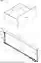
FIG. 1 is a perspective view of an embodiment of a drawer,
FIG. 2 is a perspective view of an embodiment of a drawer sidewall,
FIG. 3 shows an outer shell of the drawer sidewall according to FIG. 2 and an enlarged section thereof,
FIG. 4 shows an outer shell of the drawer sidewall according to FIG. 2 and with an enlarged section,
FIG. 5 is a side view of the section illustrated in FIG. 4, and
FIG. 6 shows an example of inserting a drawer bottom into the groove-shaped receiving channel of a drawer sidewall, together with an enlarged section of the drawer sidewall from the region of the groove-shaped receiving channel.
DETAILED DESCRIPTION OF THE INVENTION
FIG. 1 shows a drawer 2 comprising two drawer sidewalls 1 spaced apart from each other and arranged substantially parallel to each other, and a drawer bottom 7, wherein edges 6 of the drawer bottom 7 are inserted into receiving channels 5 of the drawer sidewalls 1. The drawer 2 includes a drawer rear wall 30 which can be hingedly connected to the at least one drawer bottom 7. As an alternative, it can also be a drawer rear wall 30 that is separate from the drawer bottom 7. A drawer front 29 can be arranged substantially parallel to the drawer rear wall 30.
FIG. 2 shows a drawer sidewall 1 according to an embodiment.
At least one profile body 25, 26, 27, preferably at least two profile bodies 25, 26, 27 spaced apart from each other in the longitudinal direction 17 of the drawer sidewall 1, preferably made of plastic, can be inserted into the drawer sidewall 1, the profile body 25, 26, 27 stabilizing the drawer sidewall 1 at least in a direction extending transversely to the longitudinal direction 21 of the drawer sidewall 1. The at least one profile body 25, 26, 27 can have a shape adapted to the inner shape of the drawer sidewall 1, and/or can be arranged in a front region of the drawer sidewall 1 and being configured to hold a drawer front panel 29, or can be arranged in a rear region of the drawer sidewall 1 and being configured to hold a drawer rear wall 30, or can be arranged in a middle region of the drawer sidewall 1.
In the specific case shown, the drawer sidewall 1 includes three profile bodies 25, 26, 27. A first profile body 25 is arranged in a front region of the drawer sidewall 1 and is configured to hold a drawer front panel 29. For this purpose, the profile body 25 includes a fastening device (not shown here) for fixing a panel fitting to be mounted to the drawer front panel 29 can be arrested. The profile body 25 can have an opening 37 into which the panel fitting can be inserted.
A coupling 34 may also be provided on the first profile body 25, via which the drawer sidewall 1 can be coupled to a pull-out guide.
The drawer sidewall 1 includes a second profile body 26 arranged in a central region. In FIG. 2, it is schematically indicated by dashed lines. The drawer sidewall 1 includes a third profile body 27, the third profile body 27 being arranged in a rear region of the drawer sidewall 1 and being configured to hold a drawer rear wall 30. This means that the drawer sidewall 1 includes at least one rear wall holder 31 configured to hold a drawer rear wall 30 transversely to the drawer sidewall 1. The rear wall holder 31 can include at least one clamping device 32 configured to clampingly hold the drawer rear wall 30. The clamping effect can be achieved, for example, by a pivotally mounted lever 33. Preferably, the lever 33 includes at least one cutting edge configured to be sunk into the material of the drawer rear wall 30.
FIG. 3 shows an outer shell 19 of the drawer sidewall 1 according to FIG. 2 and an enlarged section thereof.
A plurality of claws 8 spaced apart from each other in the longitudinal direction 17 of the receiving channel 5 is provided on the at least one receiving channel 5 for fixing the edge 6 of the drawer bottom 7. Preferably, the claws 8 are substantially identical in design. For example, a total of four claws 8 can be provided. The at least one groove-shaped receiving channel 5 extends in the longitudinal direction 21 of the drawer sidewall 1, and/or extends substantially over the entire length 22 of the drawer sidewall 1 (see also FIG. 2).
FIGS. 4 and 5 show further advantageous details that can be implemented individually or in combination with each other.
The groove-shaped receiving channel 5 extends between two substantially parallel limbs 3, 4, into which an edge 6 of a drawer bottom 7 is insertable. A claw 8 is provided on the receiving channel 5 for fixing, preferably clamping, the edge 6 of the drawer bottom 7. The at least one claw 8 is inclined relative to one of the limbs 3, 4 of the receiving channel 5 at an angle 9 between 45° and 85°, preferably between 50° and 80°, and particularly preferably between 55° and 75°. The receiving channel 5 can have a channel base 35. It is advantageous for the at least one claw 8 to be inclined in a direction towards the channel base 35. The at least one claw 8 can be connected to a vertical limb 36, the vertical limb 36 adjoining one of the limbs 3, 4.
The at least one claw 8 has a plurality of tips 10 at its end, and a minimum distance 11 between the tips 10 and an opposite limb 3 of the at least one receiving channel 5 is less than 10 mm, preferably less than 8 mm, and particularly preferably less than 6 mm. A distance 12 between the two limbs 3, 4 of the at least one receiving channel 5 is less than 10 mm, preferably less than 8 mm, and particularly preferably less than 6 mm.
The at least one claw 8 has at least three, preferably four or five, tips 10 at its end. The at least one claw 8 has a plurality, preferably equidistant, tips 10 at its end, preferably with a distance 13 between two adjacent tips 10 of between 2 mm and 5 mm. A width 39 of the outer tips 10 of the claw 8 can be between 10 mm and 20 mm, for example approximately 15 mm. The at least one claw 8 includes a plurality of tips 10 at its end, and at least one of the tips 10 is confined by two limbs 14, 15 that form an angle 16 between 80° and 120°, preferably between 90° and 110°, and/or wherein at least one of the tips 10 has the shape of an isosceles triangle.
The least one claw 8 projects into the at least one receiving channel 5. In this context, it is particularly advantageous for the at least one claw 8 to project between 0.5 mm and 2.0 mm, for example approximately 1.5 mm, into the receiving channel 5. The height of the projecting section of the claw 8 is indicated by the reference numeral 38.
At least one inner surface 18 of the drawer sidewall 1, preferably an entire outer shell 19 of the drawer sidewall 1, is formed from a single piece of sheet metal. The at least one receiving channel 5 and/or the at least one claw 8 is or are integrally formed into the inner surface 18. Preferably, the drawer sidewall 1 includes an outer surface 20 that is aligned substantially parallel to the inner surface 18.
The drawer sidewall 1 is substantially cuboid in shape and/or is substantially rectangular in a cross-sectional plane extending perpendicular to the longitudinal direction 21 of the drawer sidewall 1. The drawer sidewall 1 has a reduced thickness 23 in the region of the groove-shaped receiving channel 5. Preferably, the thickness 23 in the region of the groove-shaped receiving channel 5 corresponds to between 50% and 75% of a thickness 24 of the drawer sidewall 1 in a region outside the groove-shaped receiving channel 5.
The drawer sidewall 1 has a substantially constant thickness 24 in a region outside the groove-shaped receiving channel 5. An outer shell 19 of the drawer sidewall 1 is formed by a hollow profile, preferably having a substantially U-shaped cross-section.
FIG. 6 shows an example of inserting a drawer bottom 7 into the groove-shaped receiving channel 5 of a drawer sidewall 1.
To mount the drawer bottom 7 to the drawer sidewall 1, an edge 6 of the drawer bottom 7 is inserted into at least one receiving channel 5 in a direction 28 extending transversely to the longitudinal direction 17 of the receiving channel 5. The at least one claw 8 digs at least partially into the material of the drawer bottom 7 and/or the at least one claw 8 is elastically deflected about an axis extending parallel to the longitudinal direction 17 of the receiving channel 5.
The ideal solution is a combination of the two effects, that is to say that the at least one claw 8 digs at least partially into the material of the drawer bottom 7, and the at least one claw 8 is elastically deflected about an axis extending parallel to the longitudinal direction 17 of the receiving channel 5. The elastic deflection allows the drawer bottom 7 to be held in place without any play. By scratching the drawer bottom 7, an additional form-locking can be achieved.
A particularly preferred embodiment of this method provides for a drawer rear wall 30, which is hingedly connected to the at least one drawer bottom 7, and the drawer rear wall 30 is at least partially inserted into the at least one rear wall holder 31 arranged on the drawer sidewall 1 when the edge 6 of the drawer bottom 7 is inserted into the at least one groove-shaped receiving channel 5.
The drawer bottom 7 may also have at least one hinged connection 40, whereby a small packaging size can be achieved in the delivery state.
Claims
1. A drawer sidewall for a drawer, comprising:
at least one groove-shaped receiving channel extending between two substantially parallel limbs, into which an edge of a drawer bottom is insertable,
wherein at least one claw is provided on the at least one receiving channel for fixing, preferably clamping, the edge of the drawer bottom, and
wherein the at least one claw is inclined relative to one of the limbs of the receiving channel at an angle between 45° and 85°, preferably between 50° and 80°, and particularly preferably between 55° and 75°.
2. The drawer sidewall according to claim 1, wherein the at least one claw includes a plurality of tips at its end, wherein a minimum distance of the tips to an opposing limb of the at least one receiving channel is less than 10 mm, preferably less than 8 mm, and particularly preferably less than 6 mm.
3. The drawer sidewall according to claim 1, wherein a distance between the two limbs of the at least one receiving channel is less than 10 mm, preferably less than 8 mm, and particularly preferably less than 6 mm.
4. The drawer sidewall according to claim 1, wherein the at least one claw has at least three, preferably four or five, tips at its end.
5. The drawer sidewall according to claim 1, wherein the at least one claw includes a plurality, preferably equidistant, tips at its end, wherein the distance between two adjacent tips is between 2 mm and 5 mm.
6. The drawer sidewall according to claim 1, wherein the at least one claw includes a plurality of tips at its end, wherein at least one of the tips is confined by two limbs that enclose an angle between 80° and 120°, preferably between 90° and 110°, and/or wherein at least one of the tips has the shape of an isosceles triangle.
7. The drawer sidewall according to claim 1, wherein the at least one claw projects into the at least one receiving channel, and/or is configured to be elastically deflected about an axis extending parallel to the longitudinal direction of the receiving channel.
8. The drawer sidewall according to claim 1, wherein on the at least one receiving channel, a plurality of claws spaced apart from each other in the longitudinal direction of the receiving channel for fastening the edge of the drawer bottom is provided, preferably wherein the claws are substantially identical in design.
9. The drawer sidewall according to claim 1, wherein at least one inner surface of the drawer sidewall, preferably an entire outer shell of the drawer sidewall, is formed from a single piece of sheet metal, and the at least one receiving channel and/or the at least one claw is or are integrally formed into the inner surface, preferably wherein the drawer sidewall has an outer surface aligned substantially parallel to the inner surface.
10. The drawer sidewall according to claim 1, wherein:
the at least one groove-shaped receiving channel extends in the longitudinal direction of the drawer sidewall, and/or extends over the entire length of the drawer sidewall, and/or
the drawer sidewall is substantially cuboid in shape and/or is substantially rectangular in a cross-sectional plane extending perpendicular to the longitudinal direction of the drawer sidewall.
11. The drawer sidewall according to claim 1, wherein:
the drawer sidewall has a reduced thickness in a region of the groove-shaped receiving channel, preferably wherein the thickness in the region of the groove-shaped receiving channel corresponds to between 50% and 75% of a thickness of the drawer sidewall in a region outside the groove-shaped receiving channel, and/or
the drawer sidewall has a substantially constant thickness in a region outside the groove-shaped receiving channel, and/or
an outer shell of the drawer sidewall is formed by a hollow profile, preferably having a substantially U-shaped cross-section.
12. The drawer sidewall according to claim 1, wherein at least one profile body, preferably at least two profile bodies spaced apart from each other in the longitudinal direction of the drawer sidewall, preferably made of plastic, is or are inserted into the drawer sidewall for stabilizing the drawer sidewall at least in a direction extending transversely to the longitudinal direction of the drawer sidewall, preferably wherein the at least one profile body:
has a shape adapted to the inner shape of the drawer sidewall, and/or
is arranged in a front region of the drawer sidewall and is configured to hold a drawer front panel, or is arranged in a rear region of the drawer sidewall and is configured to hold a drawer rear wall, or is arranged in a middle region of the drawer sidewall.
13. The drawer sidewall according to claim 1, wherein the drawer sidewall comprises at least one rear wall holder configured to hold a drawer rear wall transversely to the drawer sidewall, and wherein the rear wall holder includes at least one clamping device configured to hold the drawer rear wall in a clamping manner.
14. A drawer comprising at least two drawer sidewalls according to claim 1, and a drawer bottom, wherein edges of the drawer bottom are inserted into the receiving channels of the at least two drawer sidewalls, preferably wherein a drawer rear wall is provided which is hingedly connected to the at least one drawer bottom.
15. A method for mounting a drawer bottom to a drawer sidewall according to claim 1, wherein an edge of the drawer bottom is inserted into at least one receiving channel in a direction extending transversely to the longitudinal direction of the receiving channel, wherein the at least one claw at partially digs into the material of the drawer bottom and/or wherein the at least one claw is elastically deflected about an axis extending parallel to the longitudinal direction of the receiving channel, preferably wherein a drawer rear wall is provided, which is hingedly connected to the at least one drawer bottom, and the drawer rear wall is inserted at least partially into at least one rear wall holder arranged on the drawer sidewall when the edge of the drawer bottom is inserted into the at least one groove-shaped receiving channel.
Images & Drawings included:


Sources:
- United States Patent and Trademark Office - verify current appl. status at the USPTO↗
Similar patent applications:
- » 20200315348
Drawer side wall having a cover profile - » 20200352328
Drawer side wall - » 20230097170
Holding device for holding a decorative panel which can be placed onto a drawer side wall - » 20200315346
Drawer side wall - » 20070228906
Drawer with at least one wooden drawer side wall - » 20250188989
METHOD FOR PRODUCING A SIDE WALL FOR A DRAWER - » 20160106211
WALL ELEMENT FOR A DRAWER SIDE AND DRAWER SIDE, DRAWER AND PIECE OF FURNITURE
Recent applications in this class:
- » 20260069034 2026-03-12
ADJUSTABLE DRAWER - » 20250151902 2025-05-15
DRAWER SIDEWALL FOR A DRAWER - » 20250143460 2025-05-08
LATERAL WALL FOR A DRAWER - » 20250143459 2025-05-08
ARRANGEMENT CONSISTING OF BODY RAIL, LOADING RAIL AND SIDE PANEL - » 20250143458 2025-05-08
SIDEWALL IN THE FORM OF A CONTAINER SIDEWALL, IN PARTICULAR A DRAWER SIDEWALL - » 20250134253 2025-05-01
CONTAINER, PREFERABLY DRAWER - » 20250072606 2025-03-06
PLASTIC DRAWER - » 20240335036 2024-10-10
DOUBLE-WALLED DRAWER FRAME - » 20240081529 2024-03-14
ASSEMBLED DRAWER - » 20240000231 2024-01-04
FURNITURE AND FURNITURE PART ASSEMBLY THEREOF