DISHWASHER WITH A TANK CLEANING SYSTEM
US20260108129A1
2026-04-23
19/361,804
2025-10-17
Smart Summary: A warewasher uses a recirculation system to clean dishes by spraying washing liquid onto them. It has a tank that collects some of this liquid and a pump that sends it back to the spray nozzles. To keep the washing tank clean, there are special nozzles that spray cleaning liquid inside the tank. This cleaning can happen whenever needed or at the end of the day. This system helps maintain cleanliness and efficiency in the warewasher. 🚀 TL;DR
Abstract:
A warewasher includes at least one washing system configured as a recirculation loop, wherein the washing system includes a nozzle system having at least one washing nozzle for spraying washing liquid onto washware, a washing tank for collecting at least a portion of the sprayed washing liquid, and a washing pump for feeding washing liquid collected in the washing tank to the at least one washing nozzle. A tank cleaning system has at least one cleaning nozzle arranged in or on the washing tank in such a way that, as needed and/or at the end of a washing shift or washing day of the warewasher, a cleaning liquid can be sprayed inside the washing tank or can be sprayed into the washing tank via the at least one cleaning nozzle of the tank cleaning system for cleaning the washing tank and/or components accommodated in the washing tank.
Applicant:
Interested in similar patents?
Get notified when new applications in this technology area are published.
Classification:
A47L15/0076 » CPC main
Washing or rinsing machines for crockery or tableware of non-domestic use type, e.g. commercial dishwashers for bars, hotels, restaurants, canteens or hospitals
A47L15/0057 » CPC further
Washing or rinsing machines for crockery or tableware; Controlling processes, i.e. processes to control the operation of the machine characterised by the purpose or target of the control Cleaning of machines parts, e.g. removal of deposits like lime scale or proteins from piping or tub
A47L15/4206 » CPC further
Washing or rinsing machines for crockery or tableware; Details; Water filter means or strainers Tubular filters
A47L15/4219 » CPC further
Washing or rinsing machines for crockery or tableware; Details; Water supply, recirculation or discharge arrangements; Devices therefor Water recirculation
A47L15/4223 » CPC further
Washing or rinsing machines for crockery or tableware; Details; Water supply, recirculation or discharge arrangements; Devices therefor Devices for water discharge, e.g. devices to prevent siphoning, non-return valves
A47L15/4225 » CPC further
Washing or rinsing machines for crockery or tableware; Details; Water supply, recirculation or discharge arrangements; Devices therefor Arrangements or adaption of recirculation or discharge pumps
A47L15/4246 » CPC further
Washing or rinsing machines for crockery or tableware; Details Details of the tub
A47L15/428 » CPC further
Washing or rinsing machines for crockery or tableware; Details; Nozzles Rotary nozzles
A47L15/00 IPC
Cleaning or polishing household articles or the like
A47L15/00 IPC
Washing or rinsing machines for crockery or tableware
A47L15/42 IPC
Washing or rinsing machines for crockery or tableware Details
Description
TECHNICAL FIELD
The present application relates to a commercial tableware or utensil washer, which is configured as a box-type warewasher or as a conveyor warewasher.
BACKGROUND
The invention is aimed at a warewasher having at least one washing zone configured as a recirculation loop. The washing zone configured as the recirculation loop comprises a nozzle system having at least one washing nozzle for spraying washing liquid onto washware, a washing tank for collecting at least a portion of the sprayed washing liquid, and a washing pump for feeding washing liquid collected in the washing tank to the at least one washing nozzle.
Optionally, the warewasher may comprise a dirt discharge system associated with the at least one washing zone, having at least one tank cover screen in order to separate dirt particles from the washing liquid flowing back into the washing tank due to gravity.
Box-type warewashers are manually loadable and unloadable warewashers. The box-type warewashers (also referred to as “batch dishwashers”) can be tableware basket sliding warewashers (“hood-type warewashers”) or front loaders (“front loader warewashers”). Front loaders can be under-counter machines, top-counter machines, or free-standing front loaders.
A warewasher configured as a box-type warewasher typically comprises a treatment chamber for the cleaning of washware. Typically, a washing tank is arranged below the treatment chamber, in which liquid can flow back from the treatment chamber due to gravity. In the washing tank, there is washing liquid, which is typically water, to which a cleaning agent may be added.
A warewasher configured as a box-type warewasher further comprises a washing system having a washing pump, a conduit system connected to the washing pump, and a nozzle system having at least one washing nozzle. The washing liquid located in the washing tank can be conveyed from the washing pump via the conduit system to the at least one washing nozzle and, through at least one washing nozzle, sprayed onto the washware in the treatment chamber. The sprayed washing liquid subsequently flows back into the washer tank due to gravity.
Conveyor warewashers are in particular flight-type warewashers or rack conveyor warewashers. Conveyor warewashers are commonly used in the commercial sector. In contrast to box-type warewashers, in which the wash items to be cleaned remain stationary in the machine during cleaning, in conveyor warewashers the washware are conveyed through different treatment zones of the conveyor warewasher.
A conveyor warewasher typically comprises at least one pre-washing zone and at least one main washing zone located downstream of the pre-washing zone(s) when viewed in the conveying direction of the washware. When viewed in the conveying direction, at least one post-washing or pre-rinsing zone and at least one rinsing zone downstream of the post-washing zone(s) are typically arranged downstream of the main washing zone(s). When viewed in the conveying direction, the washware received either directly on the conveyor belt or held by racks typically run in the conveying direction through the inlet tunnel, the subsequent pre-washing zone(s), main washing zone(s), post-washing zone(s), rinsing zone(s), a drying zone, and into an outlet path.
The aforementioned washing zones of the conveyor warewasher are each associated with a washing system comprising a washing pump and a conduit system (washing conduit system) connected to the washing pump, via which washing liquid is fed to the nozzle system or the at least one washing nozzle of the nozzle system. The washing liquid fed to the at least one washing nozzle of the nozzle system is sprayed onto the washware in the respective washing zones of the conveyor warewasher, which are conveyed by a conveyor apparatus of the conveyor warewasher through the respective washing zones. Each treatment zone is associated with a tank in which liquid sprayed by the washing nozzles is received and/or in which liquid is provided for the nozzle systems of the respective treatment zones.
In conveyor warewashers commonly known from the prior art, rinsing liquid in the form of fresh water, which can be pure or can be mixed with further additives such as a rinsing agent, is sprayed via the spray nozzles of the rinsing zone onto the washware. At least a portion of the sprayed rinsing liquid is conveyed from zone to zone in a cascading system counter to the conveying direction of the washware.
The sprayed rinsing liquid is collected in a tank (post-washing tank) of the post-washing zone, from which it is conveyed via the washing pump system of the washing system belonging to the post-washing zone to the spray nozzles (post-washing nozzles) of the post-washing zone. In the post-washing zone, washing liquid is rinsed off of the washware. The resulting liquid flows into the washing tank of the at least one main washing zone, which is upstream of the post-washing zone when viewed in the conveying direction of the washware. Here, a cleaning agent is typically added to the liquid, and then the liquid is sprayed onto the washware by a pumping system belonging to the washing system of the main washing zone (washing pump) via the nozzles (washing nozzles) of the main washing zone. From the washing tank of the main washing zone, the liquid then flows into the pre-washing tank of the pre-washing zone, unless a further main washing zone is provided. The liquid in the pre-washing tank is sprayed onto the items to be washed by a pumping system belonging to the washing system of the pre-washing zone (pre-washing pump) via the pre-washing nozzles of the pre-washing zone, in order to remove coarse impurities from the washware.
Typically, warewashers are equipped with rinsing pumps that feed the rinsing liquid to be sprayed to the conduit system of the rinsing zone. This in particular ensures a virtually constant volume flow rate of the rinsing liquid in the rinsing zone. However, it is also contemplated to use the on-site conduit pressure, for example the pressure of the fresh water supply, in order to supply the rinsing liquid to the conduit system of the rinsing zone. In the latter case, an actuatable valve can be provided between the conduit system and the spray nozzles of the rinsing zone in order to be able to achieve a temporary or complete interruption of the feeding of rinsing liquid to the spray nozzles.
Regardless of whether a warewasher is configured as a box-type warewasher or as a conveyor warewasher, commercial warewashers thus typically comprise at least one washing zone configured as a recirculation loop, which comprises a nozzle system having at least one washing nozzle for spraying washing liquid onto the washware, a washing tank for collecting at least a portion of the sprayed washing liquid, and a washing pump for feeding liquid collected in the washing tank to the at least one washing nozzle.
Because a washing zone configured as a recirculation loop is used in order to clean the items to be washed, at least a portion of the washing liquid already sprayed in the washing zone is guided in a loop, so that there is a risk that the dirt particles removed from the washware will be exponentially pulverized due to the permanent circulation of the washing liquid and thus will no longer be easily separated from the washing liquid through the use of screening apparatuses, etc. Accordingly, there is a risk that, with a washing zone configured as a recirculation cycle, the dirt load of the washing liquid in the washing zone increases with increasing washing time, so that the risk of resoiling of washware increases, and the overall washing result deteriorates.
This problem occurs in particular in the pre-washing or main washing zones of a warewasher configured as a conveyor warewasher. Because, in the case of conveyor warewashers, the flow direction of the washing liquid used is cascadingly counter to the conveying direction of the washware to be cleaned, the dirt concentration of the washing liquid in the at least one pre-washing zone is the greatest compared to the dirt concentration of the washing liquid in the remaining treatment zones, as the most dirt accrues in the pre-washing zone.
On the other hand, it cannot be avoided that, over the runtime of a warewasher configured as a conveyor warewasher, a portion of the more soiled washing liquid of the pre-washing zone is “dragged” by the conveyance of the washware into the at least one main washing zone downstream of the pre-washing zone. As a result, the dirt load of the washing liquid in the main washing zone increases, and, consequently, the rinsing result in the main washing zone can also deteriorate.
In order to separate the dirt particles introduced into the warewasher from the washing liquid used for rinsing the washware, it is well known to use screening apparatuses in the form of dirt screening baskets in which the dirt particles introduced into the warewasher are collected. In the case of warewashers configured as box-type warewashers, such a dirt screening basket is typically arranged in the sump of the treatment chamber above the washing tank.
On the other hand, with regard to warewashers configured as conveyor warewashers, it is known to equip at least the pre-washing tank associated with the pre-washing zone, and preferably also the main washing tank associated with the at least one main washing zone, with flat screens and dirt screening baskets.
In the operation of the warewasher configured as a box-type warewasher or as a conveyor warewasher, the dirt particles rinsed off of the washware with the aid of the circulating washing water fall onto the flat screens due to gravity. There, the dirt particles are separated from the washing liquid flowing back into the corresponding washing tank. The separated dirt particles are then typically flushed into a dirt screening basket.
Regardless of whether the warewasher is configured as a box-type warewasher, in particular as a hood-type warewasher or as a conveyor warewasher, the warewasher is or must be cleaned accordingly at least at the end of each commercial washing day or at the end of a washing shift. A plurality of work steps to be performed manually are involved in this process.
To clean, for example, a conveyor warewasher, the washing arms as well as the screen systems of the individual wash systems must first be removed. Since a conveyor washer typically has a plurality of wash zones arranged in series and thus a corresponding number of wash systems, these work steps must be carried out several times.
The removed screen systems are then manually sprayed with water and additionally—depending on the degree of contamination—manually scrubbed.
In particular, the corresponding washing tanks of the conveyor warewasher must also be manually sprayed with water and, if necessary, scrubbed manually. The washing tanks in the area of the loading zone of a conveyor warewasher, which are some of the most contaminated treatment zones, are sprayed with water during the cleaning process and partially cleaned manually with a cleaning wipe (if necessary) as well as, if applicable, with the aid of a cleaning solution.
After the individual treatment zones of a conveyor warewasher have been completely emptied, at the end of each washing day each treatment zone, in particular each washing tank of each treatment zone, is usually sprayed with warm water and cleaned manually (if necessary) with a cleaning wipe as well as, if applicable, with the aid of a cleaning solution.
The interior cleaning also includes corresponding inspection doors of a conveyor warewasher, which are typically designed as sliding doors or swing doors.
The total cleaning of a conveyor washer takes between 30-40 minutes, depending on the machine size, with the fresh water quantity used for machine cleaning being between 400 liters and 600 liters.
To clean a box-type warewasher, in particular a hood-type warewasher, at the end of a commercial day, at least the washing tank must be cleaned in a similar manner. Here as well, a plurality of work steps to be performed manually are involved in this process.
To clean, for example, a tableware basket sliding warewasher, you must first remove the washing and rinsing arms of the washing system as well as the screen system. The removed screen system is then manually sprayed, typically with warm water, and additionally—depending on the degree of contamination—manually scrubbed. Furthermore, after the treatment chamber of the warewasher has been completely emptied, it must generally be sprayed with warm water and cleaned manually (if necessary) with a cleaning cloth as well as, if necessary, with the aid of a cleaning solution.
The overall interior cleaning of a tableware basket sliding warewashers takes between 10 and 30 minutes, depending on the machine size, with the fresh water quantity used for machine cleaning being between 60 liters and 120 liters.
SUMMARY
The object of the present invention is to specify a warewasher of the above-mentioned type, in which the cleaning to be carried out, in particular at the end of a commercial day, can be designed more efficiently. In particular, a warewasher is to be specified, in which at least a part of the work steps required for the interior cleaning of the warewasher can be simplified or even eliminated in order to save personnel in this way and at the same time reduce the resources used for cleaning (water, energy, chemicals).
Accordingly, the invention relates in particular to a warewasher having at least one washing system configured as a recirculation loop. The warewasher according to the invention is in particular a tableware or utensil warewasher, which is configured either as a box-type warewasher or as a conveyor warewasher.
The at least one washing system of the warewasher according to the invention comprises a nozzle system having at least one washing nozzle for spraying washing liquid onto the washware to be cleaned, a washing tank for collecting at least a portion of the sprayed washing liquid, and a washing pump for feeding washing liquid collected in the washing tank to the at least one washing nozzle.
According to the invention, it is in particular provided that the warewasher comprises a tank cleaning system associated with the washing tank and having at least one cleaning nozzle disposed in or on the washing tank in such a way that, in particular as needed and preferably at the end of a washing shift or washing day of the warewasher, a cleaning liquid can be sprayed inside the washing tank or can be sprayed into the washing tank via the at least one cleaning nozzle of the tank cleaning system for cleaning the washing tank and/or components accommodated in the washing tank.
The advantages achievable with the solution according to the invention are obvious. By having a tank cleaning system associated with the washing tank, manual cleaning work in the area of the wash tank warewasher is eliminated or at least significantly reduced in an easy-to-implement, yet effective way. This significantly reduces manual cleaning for the operator of the warewasher for the overall machine.
With the solution according to the invention, the operator of the warewasher only needs to remove, empty and clean a coarse dirt collection tank of the warewasher during daily cleaning.
In a preferred implementation of the solution according to the invention, it is provided that the warewasher comprises a dirt collection system associated with the washing tank with a tank cover screen, wherein the tank cover screen is configured to separate dirt particles from the washing liquid flowing back into the washing tank by gravity. In particular, it is provided that the at least one cleaning nozzle of the tank cleaning system is disposed in the washing tank below the tank cover screen.
Preferably, the at least one cleaning nozzle of the tank cleaning system is disposed in the washing tank and/or is configured so as to apply the cleaning liquid to a bottom of the tank cover screen, at least in some regions, in particular as needed and preferably at the end of a washing shift or a washing day of the warewasher.
According to further developments of the above-mentioned design variants of the warewasher according to the invention, it is provided that the dirt collection system of the warewasher comprises a dirt collection region, which is disposed at least partially or in regions in the washing tank and open upwards, for collecting the dirt particles separated from the washing liquid by means of the tank cover screen.
It is useful for the at least one cleaning nozzle of the tank cleaning system to be disposed in the washing tank and/or configured so as to apply the cleaning liquid to the dirt collection region of the dirt collection system, at least in some regions, in particular as needed and preferably at the end of a washing shift or a washing day of the warewasher.
In a preferred further development of the above-mentioned design variant of the warewasher according to the invention, it is provided that the dirt collection region of the dirt collection system comprises a wall area permeable to washing liquid, in particular in the form of a screen and preferably in the form of a fine screen.
The at least one cleaning nozzle of the tank cleaning system should be disposed in the washing tank and/or configured so as to apply the cleaning liquid to the wall area of the dirt collection region permeable to washing liquid, at least in some regions, in particular as needed and preferably at the end of a washing shift or a washing day of the warewasher.
According to implementations of the dirt collection system associated with the washing tank of the warewasher according to the invention, it is provided that the warewasher further comprises a dirt discharge system connected to the dirt collection region of the dirt collection system with a dirt discharge pipe system via which the dirt collection region can be emptied as needed.
In particular, according to implementations of the warewasher according to the invention, it is provided that the tank cover screen is disposed over the dirt collection region and comprises a drain slope towards a feed opening. It is useful that the dirt collection region, which is formed such that it is open upwards, is disposed below the feed opening such that the dirt particles separated from the washing liquid by means of the tank cover screen pass into the dirt collection region via the feed opening.
In this context, it is particularly useful that the tank cover screen is configured in a funnel-like manner, at least in regions, and that the feed opening is configured within the funnel-like region of the tank cover screen and preferably in a tapered region of the funnel-like region of the tank cover screen.
According to implementations of the warewasher according to the invention, it is provided that at least one sensor for fill level monitoring and/or at least one heating element are/is arranged at least partially or in regions in the washing tank of the warewasher.
In this context, the at least one cleaning nozzle of the tank cleaning system should be disposed in the washing tank and/or configured so as to apply the cleaning liquid to the at least one sensor and/or the at least one heating element, at least in regions, in particular as needed and preferably at the end of a washing shift or a washing day of the warewasher.
Preferably, the at least one cleaning nozzle of the tank cleaning system is disposed, and in particular integrated in a side wall region of the washing tank. In particular, according to embodiments of the warewasher according to the invention, all of the cleaning nozzles of the tank cleaning system are disposed, and in particular integrated, in corresponding side wall regions of the washing tank.
An upper level of the washing tank may be defined by the fact that in this level there is an edge area of a tank cover screen associated with the washing tank. A lower level of the washing tank may be defined by a bottom surface of the washing tank forming the bottom of the washing tank. The distance between the lower level and the upper level defines the depth T of the washing tank.
In embodiments of the warewasher according to the present invention, it is provided that the at least one cleaning nozzle and preferably all cleaning nozzles of the tank cleaning system are disposed, and in particular integrated in an upper side wall region of the washing tank.
Particularly efficient tank cleaning can be achieved using the at least one cleaning nozzle if the at least one cleaning nozzle is disposed, and in particular integrated in a side wall region of the washing tank which—measured from the bottom surface of the washing tank forming the base—lies in a range between 55% and 85% of the depth T and in particular in a range between 60% and 75% of the depth T.
The tank cleaning system should be configured in particular to clean areas of the washing tank that are difficult to access for the operator of the warewasher. In this context, it is thus provided that the at least one washing system is at least partially or in some regions accommodated in a treatment chamber or treatment zone of the warewasher, wherein the treatment chamber or treatment zone of the warewasher has a particularly manually lockable access opening. In this context, the at least one cleaning nozzle of the tank cleaning system should be disposed in or on a side wall region of the washing tank opposite to the access opening of the warewasher or the treatment chamber or treatment zone of the warewasher.
According to one aspect of the present invention, the tank cleaning system comprises a control device. Alternatively, it is contemplated that the tank cleaning system may be associated with a control device.
The control device is configured so as to actuate the tank cleaning system as needed or according to a previously defined or definable sequence of events in such a way that the cleaning liquid is sprayed inside the washing tank or is sprayed into the washing tank via the at least one cleaning nozzle of the tank cleaning system.
A waste water pump may be associated with the washing tank of the warewasher, the suction side of which is or may be fluidly connected to the washing tank in order to pump at least a portion of the washing liquid received in the washing tank, in particular as needed or in particular after a previously defined or definable sequence of events, out of the washing tank and then to feed the at least one pumped portion of the washing liquid received in the washing tank to a heat exchanger of the warewasher or a waste water connection of the warewasher or a waste water regeneration device of the warewasher.
In this context, it is useful that the control device of the tank cleaning system is configured so as to actuate the tank cleaning system, preferably automatically and in particular selectively automatically, such that the cleaning liquid is sprayed inside the washing tank or sprayed into the washing tank via the at least one cleaning nozzle of the tank cleaning system when at least a portion of the washing liquid received in the washing tank is pumped out by means of the waste water pump.
Alternatively or additionally, it is contemplated for the warewasher to have sensors configured to sense a level of soiling of the washing liquid received in the washing tank.
In this context, the control device is configured to determine a time and/or a period of time when and/or during which the cleaning liquid is to be sprayed with the help of the at least one cleaning nozzle of the tank cleaning system, in particular as needed, depending on the detected degree of soiling of the washing liquid received in the washing tank.
Alternatively or additionally, the control device should be configured to establish an amount of cleaning liquid to be sprayed per unit of time using the at least one cleaning nozzle of the tank cleaning system, depending on the level of soiling of the washing liquid received in the washing tank.
According to design variants of the warewasher according to the invention, the washing tank is associated with a sensor which is configured so as to at least indirectly detect the level of soiling of the washing liquid received in the washing tank by means of a turbidity of the washing liquid received in the washing tank and/or by means of a washing liquid fill level of the washing liquid received in the washing tank.
The cleaning liquid, which is sprayed as needed by the at least one cleaning nozzle of the tank cleaning system, is preferably fresh water, in particular cool fresh water, heated water, in particular heated fresh water, or regenerated washing liquid from the washing tank. A cleaning chemical may optionally be added to the cleaning liquid.
The tank cleaning system preferably comprises a liquid feed that is or can be fluidly connected to the at least one cleaning nozzle, via which the at least one cleaning nozzle can be supplied as needed with the cleaning liquid to be sprayed by the cleaning nozzle.
In this context, it is useful that the liquid feed of the tank cleaning system comprises at least one valve that can be actuated via a control device of the warewasher and/or at least one cleaning liquid pump that can be actuated via a control device of the warewasher, via which an amount of cleaning liquid to be fed or supplied per unit of time to the at least one cleaning nozzle of the tank cleaning system can be set.
With respect to the at least one cleaning nozzle of the tank cleaning system, it has been shown to be particularly advantageous if the cleaning nozzle is embodied as a rotary nozzle and configured to produce a rotating spray jet.
According to implementations of the at least one cleaning nozzle of the tank cleaning system, it is provided that the at least one cleaning nozzle comprises a housing with a fluid inlet and a rotor rotatably supported in or on the housing with two exit openings at least partially opposite one another.
Of course, other embodiments for the tank cleaning system cleaning nozzle are also conceivable.
BRIEF DESCRIPTION OF THE DRAWINGS
The invention is described in further detail below with reference to the accompanying drawings.
The following are shown:
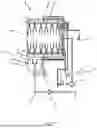
FIG. 1 is a hydraulic diagram of an exemplary embodiment of the warewasher according to the present invention;
FIG. 2A shows schematically and in an exploded view, an exemplary embodiment of a screen system used in the warewasher according to the invention;
FIG. 2B shows schematically and in an isometric view, the screen system according to FIG. 2A in the assembled state;
FIG. 3 shows schematically, and in an isometric view, an exemplary embodiment of a warewasher designed as a hood-type warewasher with an exemplary embodiment of a tank cleaning system, without a corresponding screen system;
FIG. 4 shows schematically and in a plan view from above, the washing tank of the warewasher according to FIG. 3;
FIG. 5 shows schematically and in a partially sectional side view, the lower region of the warewasher according to FIG. 3 having the washing tank, a dirt collection system at least partially or in some regions received in the washing tank, and the tank cleaning system; and
FIG. 6 shows schematically and in a side view, the lower region of the warewasher according to FIG. 5, without the dirt collection region of the dirt collection system.
DETAILED DESCRIPTION
Commercial warewashers 1 are designed for cleaning large quantities of washware in as short a time as possible. In a hood-type warewasher from the present applicant, the duration of the preset standard program, which is typically used for normally soiled washware such as plates, bowls, cups, and glasses, is only 70 seconds. This means that the theoretical capacity of the hood-type warewasher is up to 52 baskets per hour.
Almost without exception, commercial warewashers 1 are equipped with rotating washing-and-rinsing systems. A washing-and-rinsing system typically consists of a washing arm and a rinsing arm 6, 7.
For example, as shown in FIG. 1, a commercial warewasher 1 has an upper as well as a lower washing and rinsing system.
During operation, the washing liquid (detergent solution) is pumped from the washing tank of the warewasher 1 to the washing arms 6 via a pipe system using a washing pump 4. The washing arms 6 are used in order to apply the washing liquid (detergent solution) to the washware to be cleaned. The dirt is removed from the washware and integrated into the washing liquid. As shown in FIG. 1, the washing liquid then flows back into the washing tank 3 of the warewasher 1 via a screen system (tank cover screen 14) that retains coarse dirt residues.
As shown in FIG. 2, the screen system of a commercial warewasher 1 typically comprises a flat screen (tank cover screen 14), a fine screen 16, and a collection tank (dirt collection region 15) for coarse food residues. The collection tank is also commonly referred to as the dirt collection region 15.
However, systems are also known in which the collection tank (dirt collection region 15) and the fine screen 16 are combined in one part.
Typically, the flat screen (tank cover screen 14) is formed as a perforated sheet. However, flat screens (tank cover screens 14) without perforations are also known.
Typically, the flat screen (tank cover screen 14) comprises perforations of 1.5 mm to 3.0 mm in diameter. However, this means that dirt particles that are less than 1.5 mm to 3.0 mm cannot be filtered out of the detergent solution. In subsequent wash programs, these are repeatedly pumped by the washing pump 4 via the washing arms 6. This allows these dirt particles to disperse and settle in the machine interior.
Coarser dirt particles (3.0 mm to 7.0 mm) are filtered out via the flat screen (tank cover screen 14) and the fine screen 16. The particles of this size are supplied via the drain pump (waste water pump 25), for example, to a waste water system. Dirt residues larger than 7.0 mm are collected in a collection tank (dirt collection region 15). This must be manually removed and cleaned at the end of the washing shift.
At the end of the washing shift, a special draining program is typically used in which the dirty water is pumped from the machine via the waste water pump 25 and flushed out of the machine interior and the top of the flat screen 14 via the rinsing system. Systems are also known in which the dirty water is drained only by removal of the respective standpipe.
During the draining program, the top side of the flat screen 14 is cleaned at least in regions and the dirt is rinsed into the collection tank (dirt collection region 15). The flat screen 14 covers the washing tank 3 during the draining program, whereby the washing tank 3 and the bottom of the flat screen 14 are not rinsed.
After the draining program, the operator is required to clean the warewasher 1 manually. To this end, the washing and rinsing arms and the components of the screen system (flat screen 14, fine screen 16 and dirt collection containers) are usually removed from the warewasher 1 and cleaned manually.
Furthermore, the machine interior including the washing tank 3 is cleaned with a relatively high manual effort. To this end, the operator usually cleans the interior including the washing tank 3 with a sponge. In the case of stubborn soiling, a brush is first used. Depending on the installation, manual spraying of the machine interior with a water hose/handheld shower is also a common practice.
The objective of the invention is to eliminate the manual cleaning effort in the area of washing tank 3 and thus significantly reduce the manual cleaning effort for the operator for the entire warewasher 1.
With the invention, the operator only has to remove, empty and clean the coarse dirt collection tank (dirt collection region 15) during the daily cleaning of the warewasher 1. This is to be implemented by a special cleaning program, which is used at the end of the washing shift in place of the previous draining program.
The aforementioned particles, which have been deposited on the surfaces, in particular of the washing tank 3, are dissolved and rinsed in the washing tank 3 and from parts of the screen system via cleaning nozzles 20 of a tank cleaning system, so that they can be conveyed from the warewasher 1 via the draining system.
In the following detailed description of the figures, the same or similarly acting components are provided with the same reference characters.
In FIG. 1, an exemplary embodiment of the warewasher 1 according to the invention is illustrated. It should be noted that this comprises only the components required for understanding the invention. Details of the warewasher 1 are subsequently illustrated with reference to the illustrations in FIG. 2A, B, and FIG. 3 through FIG. 6.
The warewasher 1 according to FIG. 1 is in particular a commercial table or utensil washer, which is configured as a hood-type warewasher.
Of course, it is also possible to configure the warewasher 1 according to the invention as a box-type warewasher or as a conveyor warewasher. The structural changes necessary for this are of course known to the person skilled in the art.
The warewasher 1 shown in FIG. 1 comprises a treatment chamber 2 with an associated wash tank 3. The wash tank 3 serves to receive a treatment liquid, which can be conveyed to a plurality of washing nozzles 5 via a washing pump 4. In particular, according to the illustrated embodiment, the wash nozzles 5 are located in the upper and lower regions of the treatment chamber 2, where a wash/rinse system with an associated washing arm 6 and a rinsing arm 7 is provided.
The upper and lower washing arms 6 are connected to the washing tank 3 via a wash line. Because the wash tank 3 is located in the lower region of the treatment chamber 2, this can result in a recirculation of the treatment liquid (wash liquid) after the spraying of the washware.
The warewasher 1 shown in FIG. 1 further comprises at least one rinsing system for providing a rinsing liquid. In the illustrated embodiment, the rinsing system consists of a reservoir 9 that contains a rinsing concentrate.
As can be seen from the illustration in FIG. 1, the reservoir 9 of the rinsing system is connected to a water heater (boiler 10) via a fluid line. The boiler 10 comprises a fresh water connection 11 through which fresh water (e.g. tap water) can be introduced into the boiler 10. The fresh water located in the boiler 10 is heated by a heating device and mixed with the rinsing concentrate of the reservoir 9. For this purpose, the rinsing concentrate is conveyed through a dosing pump from the reservoir 9 to the boiler 10. The rinsing liquid resulting from a combination of fresh water and rinsing concentrate can be conveyed to a plurality of rinsing nozzles 13 via a rinsing pump 12 and the associated rinsing lines. Similar to the washing nozzles 5, the rinsing nozzles 13 are also located inside the treatment chamber 2 of the warewasher 1, namely in an upper and lower rinsing arm 7, respectively.
As can in particular be seen in the illustrations in FIG. 3 to FIG. 6, the exemplary embodiment of the warewasher 1 according to the invention shown schematically in the drawings comprises a tank cleaning system associated with the washing tank 3.
The tank cleaning system comprises a plurality of cleaning nozzles 20 disposed in the washing tank 3, which are configured, in particular as needed and preferably at the end of a washing shift or a washing day of the warewasher 1 to spray cleaning liquid into the washing tank 3 or to spray the washing tank 3 to clean the washing tank 3 and components accommodated in the washing tank 3 accordingly.
In so doing, the cleaning nozzles 20 of the tank cleaning system are preferably disposed below the tank cover screen 14, as indicated in FIG. 5 and FIG. 6. Thus, with the aid of the cleaning nozzles 20, the cleaning liquid is applied to a bottom side of the tank cover screen 14 at least in regions.
The dirt collection region 15 of the dirt collection system can be seen in a side view in FIG. 5.
The dirt collection region 15 is open towards the top and serves to collect the dirt particles separated from the washing liquid by means of the tank cover screen 14. It is provided that the cleaning nozzles 20 of the tank cleaning system are disposed and configured in the washing tank 3 in order to also apply the cleaning liquid to the dirt collection region 15, if necessary.
It can also be seen in the illustration in FIG. 5 that the dirt collection region 15 comprises a wall area in the form of a fine screen 16. Cleaning liquid is also applied to this fine screen 16 if necessary using the cleaning nozzle 20 of the tank cleaning system.
The hydraulic diagram according to FIG. 1 shows that a dirt discharge pipe system 17 can be fluidly connected to the dirt collection region 15, via which the dirt collection region 15 can be emptied as needed. In this respect, the tank cover screen 14 (not shown in FIG. 1) is disposed over the dirt collection region 15 and—as shown in FIG. 2A and FIG. 2B—comprises a drain slope towards a feed opening 18. The dirt collection region 15 is disposed below the feed opening 18 such that the dirt particles separated from the washing liquid via the feed opening 18 enter the dirt collection region 15 with the aid of the tank cover screen 14.
At least one sensor 19 for level monitoring and at least one heating element can be disposed at least partially or in regions in the washing tank 3 of the warewasher 1. The cleaning nozzles 20 of the tank cleaning system should also be disposed and configured in the washing tank 3 in order to be able to also apply cleaning liquid to the at least one sensor 19 or the at least one heating element as needed.
In the embodiment shown in the drawings (cf. in particular FIG. 3 to FIG. 6) of the warewasher 1 according to the invention, the cleaning nozzles 20 of the tank cleaning system are disposed or integrated in corresponding side wall areas of the washing tank 3. The cleaning nozzles 20 are in particular disposed in an upper level of the corresponding side wall region of the washing tank 3.
In FIG. 6, a top level A of the washing tank 3, in which an edge area of a tank cover screen 14 associated with the washing tank 3 lies, is shown, along with a bottom level B, in which a bottom surface of the washing tank 3, which forms the base of the washing tank 3. The distance between these two levels defines the depth T of the washing tank 3.
In particular, it is provided that the cleaning nozzles 20 are disposed and particularly integrated in a side wall region of the washing tank 3, which lies in a range between 55% and 85% of the depth T and in particular between 60% and 75% of the depth T, as measured from the bottom surface of the washing tank 3 forming the base of the washing tank 3.
At least some of the cleaning nozzles 20 of the tank cleaning system should be disposed in a side wall region of the washing tank 3, which is disposed opposite an access opening of the warewasher 1 (cf. the top plan view in FIG. 4).
The tank cleaning system comprises a control device 50 (e.g., any circuit (e.g., solid state, application specific integrated circuit (ASIC), an electronic circuit, a combinational logic circuit, a field programmable gate array (FPGA)), processor(s) (e.g., shared, dedicated, or group—including hardware or software that executes code), software, firmware and/or other components, or a combination of some or all of the above, that carries out the control functions of the machine or the control functions of any component thereof) indicated on the schematic drawing, which is configured so as to actuate the tank cleaning system as needed or according to a previously defined or definable sequence of events in such a way that the cleaning liquid is sprayed inside the washing tank 3 via the cleaning nozzles 20 of the tank cleaning system.
As already indicated in connection with the hydraulic diagram in FIG. 1, the washing tank 3 is associated with a waste water pump 25, the suction side of which is fluidly connected or connectable to the washing tank 3 in order to pump at least a portion of the washing liquid accommodated in the washing tank 3, in particular as needed, or in particular after a previously defined or devinable sequence of events, from the washing tank 3. The drained washing liquid is supplied to either a heat exchanger of the warewasher 1 (not shown in the drawings) or a drainage connection of the warewasher 1 or a drainage regeneration device of the warewasher 1.
The control device 50 of the tank cleaning system is in particular configured so as to actuate the tank cleaning system, in particular automatically and preferably selectively automatically, such that the cleaning liquid is sprayed into the washing tank 3 via the cleaning nozzles 20 of the tank cleaning system when at least a portion of the washing liquid received in the washing tank 3 is pumped out by means of the waste water pump 25.
Alternatively or additionally, the control device 50 is configured to determine a time or a time period for when or during which the cleaning liquid in washing tank 3 is to be sprayed with the aid of the cleaning nozzles 20 of the tank cleaning system, depending on a degree of soiling of the washing fluid received in the washing tank 3 detected using sensors.
The control device 50 may also be configured to establish an amount of cleaning liquid to be sprayed per unit of time using the cleaning nozzles 20 of the tank cleaning system, depending on the degree of soiling of the washing liquid received in washing tank 3 detected using sensors.
The soiling or degree of soiling of the washing liquid received in the washing tank 3 can be detected, for example with the aid of a turbidity sensor.
Alternatively or additionally, the washing liquid level of the washing liquid received in the washing tank 3 may also be used to infer the degree of soiling of the washing liquid received in the washing tank 3.
Although this is not explicitly illustrated in the drawings, the tank cleaning system comprises a liquid feed that is or can be fluidly connected to the cleaning nozzles 20 of the tank cleaning system, via which the cleaning nozzles 20 of the tank cleaning system can be supplied as needed with the cleaning liquid to be sprayed.
The cleaning liquid is preferably fresh water, particularly cold fresh water. Alternatively, of course, it is also contemplated to use heated water as the cleaning liquid, in particular heated fresh water, or regenerated washing liquid from the washing tank 3. A cleaning chemical may also be added to the cleaning liquid, if necessary.
The cleaning nozzles 20 of the tank cleaning system are preferably designed as rotary nozzles and are configured so as to generate a rotating spray jet.
In particular, the cleaning nozzle 20 comprises a housing 21 having a fluid inlet 22 and a rotor 23 rotatably mounted in or on the housing 21, comprising two outlet openings 24 lying at least partially opposite one another.
The invention is not limited to the embodiments shown in the drawings, but results when all of the features disclosed herein are considered together.
LIST OF REFERENCE NUMERALS
-
- 1 Warewasher
- 2 Treatment chamber
- 3 Washing tank
- 4 Washing pump
- 5 Wash nozzle
- 6 Washing arm
- 7 Rinsing arm
- 9 Reservoir for rinsing concentrate
- 10 Water heater/boiler
- 11 Water heater fresh water connection
- 12 Rinsing pump
- 13 Rinsing nozzle
- 14 Tank cover screen
- 15 Dirt collection region
- 16 Fine screen
- 17 Dirt discharge pipe system
- 18 Feed opening
- 19 Fill level monitoring sensor
- 20 Cleaning nozzle
- 25 Wastewater pump
- 50 Control device 50
- A Upper level of wash tank
- B Ground surface/lower level of wash tank
- T Depth of wash tank
Claims
1. A warewasher having at least one washing system configured as a recirculation loop, wherein the at least one washing system comprises a nozzle system having at least one washing nozzle for spraying washing liquid onto the washware, a washing tank for collecting at least a portion of the sprayed washing liquid, and a washing pump for feeding washing liquid collected in the washing tank to the at least one washing nozzle,
wherein the warewasher comprises a tank cleaning system associated with the washing tank and having at least one cleaning nozzle arranged in or on the washing tank in such a way that, as needed and/or at the end of a washing shift or a washing day of the warewasher, a cleaning liquid can be sprayed inside the washing tank or can be sprayed into the washing tank via the at least one cleaning nozzle of the tank cleaning system for cleaning the washing tank and/or components accommodated in the washing tank.
2. The warewasher according to claim 1, wherein the warewasher comprises a dirt collection system associated with the washing tank and having a tank cover screen, wherein the tank cover screen is configured so as to separate dirt particles from the washing liquid that has been sprayed and flows back into the washing tank due to gravity, wherein the at least one cleaning nozzle of the tank cleaning system is arranged in the washing tank below the tank cover screen .
3. The warewasher according to claim 2, wherein the at least one cleaning nozzle of the tank cleaning system is arranged in the washing tank and/or is configured so as to apply the cleaning liquid to a bottom of the tank cover screen, at least in some regions, as needed and at the end of the washing shift or the washing day of the warewasher.
4. The warewasher according to claim 2, wherein the dirt collection system comprises a dirt collection region that is arranged at least partially or regionally in the washing tank and opens upwardly for collecting the dirt particles separated from the washing liquid by means of the tank cover screen, and wherein the at least one cleaning nozzle of the tank cleaning system is arranged in the washing tank and/or configured so as to apply the cleaning liquid to the dirt collection region, at least in some regions, as needed and at the end of the washing shift or the washing day of the warewasher.
5. The warewasher according to claim 4, wherein the dirt collection region comprises a wall region that is permeable to the washing liquid, and wherein the at least one cleaning nozzle of the tank cleaning system is arranged in the washing tank and/or configured so to apply the cleaning liquid to the washing liquid-permeable wall region of the dirt collection region, at least in some regions, as needed and at the end of the washing shift or the washing day of the warewasher.
6. The warewasher according to claim 4, wherein the warewasher further comprises a dirt discharge system fluidly connected to the dirt collection region and having a dirt discharge pipe system, via which the dirt collection region of the warewasher can be emptied as needed.
7. The warewasher according to claim 4, wherein the tank cover screen is arranged over the dirt collection region and comprises a discharge slope towards a feed opening, wherein the dirt collection region which is configured so as to open upwardly is arranged below the feed opening of the tank cover screen, such that the dirt particles separated from the washing liquid by means of the tank cover screen arrive at the dirt collection region via the feed opening.
8. The warewasher according to claim 7, wherein the tank cover screen is configured with a funnel-like region, at least regionally, and wherein the feed opening is configured within the funnel-like region of the tank cover screen.
9. The warewasher according to claim 1, wherein at least one sensor for monitoring the fill plane and/or at least one heating element are arranged at least partially or regionally in the washing tank, and wherein the at least one cleaning nozzle of the tank cleaning system is arranged in the washing tank and/or configured so as to apply cleaning liquid to the at least one sensor and/or the at least one heating element, at least regionally, as needed and at the end of the washing shift or the washing day of the warewasher.
10. The warewasher according to claim 1, wherein the at least one cleaning nozzle of the tank cleaning system or all cleaning nozzles of the tank cleaning system, is/are integrated or arranged in at least one side wall region of the washing tank.
11. The warewasher according to claim 10, wherein the washing tank has a depth that is defined between an upper plane, in which an edge region of a tank cover screen associated with the washing tank lies, and a lower plane, in which a bottom surface of the washing tank forming the floor of the washing tank lies, and wherein the at least one cleaning nozzle, and the side wall region is an upper side wall region of the washing tank.
12. The warewasher according to claim 11, wherein the upper side wall region. lies in a range between 55% and 85% of the depth
13. The warewasher according to claim 1, wherein the at least one washing system is at least partially or regionally accommodated in a treatment chamber or in a treatment zone of the warewasher, wherein the treatment chamber or treatment zone of the warewasher comprises an access opening that is manually lockable, and wherein at least one cleaning nozzle of the tank cleaning system is arranged in or at a side wall region of the washing tank lying opposite the access opening.
14. The warewasher according to claim 1, wherein the tank cleaning system comprises a control device, or wherein a control device is associated with the tank cleaning system, wherein the control device is configured so as to actuate the tank cleaning system as needed or according to a previously defined or definable sequence of events in such a way that the cleaning liquid is sprayed inside the washing tank or is sprayed into the washing tank via the at least one cleaning nozzle of the tank cleaning system.
15. The warewasher according to claim 1, wherein a waste water pump is associated with the washing tank of the warewasher, the suction side of which is or can be fluidly connected to the washing tank in order to pump at least a portion of the washing liquid received in the washing tank, as needed and/or after a previously defined or definable sequence of events, out of the washing tank and then to feed the at least one pumped portion of the washing liquid received in the washing tank to a heat exchanger of the warewasher or a waste water port of the warewasher or a waste water regeneration device of the warewasher.
16. The warewasher according to claim 14, wherein the control device is configured so as to actuate the tank cleaning system, such that the cleaning liquid is sprayed inside the washing tank or sprayed into the washing tank via the at least one cleaning nozzle of the tank cleaning system when at least a portion of the washing liquid received in the washing tank is pumped out by means of the waste water pump.
17. The warewasher according to claim 14, wherein the warewasher comprises a sensor, which is configured so as to detect a level of soiling of the washing liquid received in the washing tank, wherein the control device is configured so as to determine, as a function of the detected level of soiling of the washing liquid received in the washing tank, a time and/or a time period when or during which, by means of the at least one cleaning nozzle of the tank cleaning system, the cleaning liquid is to be sprayed, and/or an amount of cleaning liquid to be sprayed per unit of time by means of the at least one cleaning nozzle of the tank cleaning system.
18. The warewasher according to claim 17, wherein the washing tank is associated with a sensor which is configured so as to at least indirectly detect the level of soiling of the washing liquid received in the washing tank by means of a turbidity of the washing liquid received in the washing tank and/or by means of a washing liquid fill level of the washing liquid received in the washing tank.
19. The warewasher according to claim 1, wherein the cleaning liquid to be sprayed as needed by the at least one cleaning nozzle of the tank cleaning system comprises fresh water or fresh water and a correspondingly metered cleaning chemical.
20. The warewasher according to claim 1, wherein the tank cleaning system comprises a liquid feed that is or can be fluidly connected to the at least one cleaning nozzle of the tank cleaning system, via which the at least one cleaning nozzle of the tank cleaning system can be supplied as needed with the cleaning liquid to be sprayed.
21. The warewasher according to claim 20, wherein the liquid feed of the tank cleaning system comprises at least one valve that can be actuated via a control device of the warewasher and/or at least one cleaning liquid pump that can be actuated via a control device of the warewasher, via which an amount of cleaning liquid to be fed or supplied per unit of time to the at least one cleaning nozzle of the tank cleaning system can be set.
22. The warewasher according to claim 1, wherein the at least one cleaning nozzle of the tank cleaning system is designed as a rotary nozzle and is configured so as to generate a rotating spray jet.
23. The warewasher according to claim 22, wherein the at least one cleaning nozzle comprises a housing having a fluid inlet and a rotor rotatably mounted in or on the housing, having two outlet openings lying at least partially opposite one another.
Images & Drawings included:


Sources:
- United States Patent and Trademark Office - verify current appl. status at the USPTO↗
Recent applications in this class:
- » 20220211243 2022-07-07
Real-time single dish cleaner - » 20220183534 2022-06-16
Straw washer system, device, and method - » 20210274994 2021-09-09
Straw washer system, device, and method - » 20200281437 2020-09-10
CLEANING DEVICE AND METHOD FOR CLEANING ARTICLES TO BE CLEANED - » 20200281436 2020-09-10
Dish washing apparatus and dish drying apparatus - » 20200000308 2020-01-02
Cleaning device and method for cleaning articles to be cleaned - » 20190298144 2019-10-03
Warewasher and associated spray arm assembly - » 20190090718 2019-03-28
Pan cleaner system and method - » 20180228341 2018-08-16
Reprocessing apparatus and a method of reprocessing a load in a reprocessing apparatus - » 20180020899 2018-01-25
Batch-type warewasher with energy retaining curtain