SOFT-ACTUATED NOZZLE ADJUSTING DEVICE FOR ABRASIVE WATER JET POLISHING
US20260109003A1
2026-04-23
19/344,463
2025-09-29
Smart Summary: A device helps adjust nozzles used in abrasive water jet polishing. It has several parts, including joints that can move, a soft sleeve connecting them, and a nozzle at the end. The soft sleeve allows flexibility between the moving parts, making adjustments easier. An abrasive hose runs through the device and connects to the nozzle for water jet polishing. Additionally, there are soft filaments around the joints to aid in the adjustment process. 🚀 TL;DR
Abstract:
A soft-actuated nozzle adjusting device for abrasive water jet polishing is provided, including an actuated joint, a soft connecting sleeve, a nozzle, an abrasive hose, and a soft adjusting filament, and at least two actuated joints are arranged. Each actuated joint includes a base body, a moving body, and an actuator element. The soft connecting sleeve is provided between two adjacent actuated joints, and two ends of the soft connecting sleeve are fixedly connected to the base body and the moving body, respectively. The nozzle is detachably connected to the moving body that is located at an end. The abrasive hose is threaded through the soft connecting sleeve and the actuated joint, and one end of the abrasive hose is provided in connection with the nozzle. A plurality of soft adjusting filaments is provided along a circumferential direction of the actuated joint.
Inventors:
- Chuanzhen HUANG 6 🇨🇳 Jinan, China
- Hongtao ZHU 19 🇨🇳 Jinan, China
- Peng YAO 18 🇨🇳 Jinan, China
- Dun LIU 12 🇨🇳 Jinan, China
- Zhaolei SONG 1 🇨🇳 Jinan, China
- Huaihao KOU 1 🇨🇳 Jinan, China
Assignee:
- SHANDONG UNIVERSITY 301 🇨🇳 Jinan, China
Applicant:
Interested in similar patents?
Get notified when new applications in this technology area are published.
Classification:
B24C5/04 » CPC main
Devices or accessories for generating abrasive blasts; Blast guns, e.g. for generating high velocity abrasive fluid jets for cutting materials Nozzles therefor
B24C3/06 » CPC further
Abrasive blasting machines or devices; Plants characterised by the arrangement of the component assemblies with respect to each other movable; portable
Description
CROSS-REFERENCE TO RELATED APPLICATIONS
This application claims priority to Chinese Application No. 202411479203.3 filed on Oct. 23, 2024, the entire contents of which are hereby incorporated by reference.
TECHNICAL FIELD
The present disclosure relates to the computer field, and in particular, to a soft-actuated nozzle adjusting device for abrasive water jet polishing.
BACKGROUND
Abrasive water jet polishing technology is a precision machining technology with the advantages of a wide range of machining materials, the absence of thermal machining effects, and the ability to meet the high shape accuracy and high surface roughness requirements needed for non-linear and complex curved parts. The technology utilizes high-speed spraying of polishing slurry mixed with fine abrasive particles to act on the surface of the workpiece, which achieves the grinding and removal of materials through the high-speed collision and shearing effect of abrasive particles. This technology, by controlling process parameters such as the pressure, angle, and spray time of the polishing slurry spray, quantitatively corrects the surface roughness of the workpiece polishing process.
However, the use of abrasive water jet polishing technology in the polishing process of the hydraulic valve body, pump casing, and other parts with a cavity structure, especially in the polishing process of the cavity structure with a smaller structural size, due to the narrow and complex cavity space, only the water jet nozzle can reach into the cavity, which leads to the need for artificial adjustment of the water jet nozzle. Thus, the polishing efficiency of the cavity is affected and the workload of the staff is increased. Additionally, the artificial adjustment of the water jet nozzle has defects of poor adjusting precision, which then affects the quality of polishing the cavity.
The present disclosure provides a soft-actuated nozzle adjusting device for abrasive water jet polishing, which improves the polishing efficiency of the inner surface of the cavity, reduces the workload of the staff member, and improves the quality of polishing the cavity.
SUMMARY
Embodiments of the present disclosure provide a soft-actuated nozzle adjusting device for abrasive water jet polishing, including an actuated joint, a soft connecting sleeve, a nozzle, an abrasive hose, and a plurality of soft adjusting filaments. At least two actuated joints may be arranged, each actuated joint may include a base body, a moving body, and an actuator element configured to drive the moving body in a direction proximate to or away from the base body. The soft connecting sleeve may be provided between two adjacent actuated joints, and two ends of the soft connecting sleeve may be fixedly connected to the base body and the moving body, respectively. The nozzle detachably may be connected to the moving body that is located at an end and may follow the moving body that is located at the end to move. The abrasive hose may be threaded through the soft connecting sleeve and the actuated joint, and one end of the abrasive hose may be provided in connection with the nozzle. The plurality of soft adjusting filaments may be provided along a circumferential direction of the actuated joint, each soft adjusting filament may be threaded through the multiple actuated joints, and each soft adjusting filament may have a stop end that abuts against the moving body that is located at the end. The actuator element may include an electromagnet provided in one of the base body and the moving body, a mating piece provided in the other of the base body and the moving body with ferromagnetic in character, and an elastic portion provided between the base body and the moving body. When the electromagnet is in an energized state, the electromagnet may generate a magnetic suction force on the mating piece to cause the moving body to overcome an elasticity of the elastic portion and move in a direction close to the base body.
In some embodiments, the moving body may be provided with a receiving cavity whose opening faces toward the base body. The base body may be provided with a guiding section extending into the receiving cavity, the guiding section may be provided with an installation cavity whose opening faces toward the moving body, and at least a portion of the elastic portion may be located in the installation cavity.
In some embodiments, a blocking portion may be provided at the opening of the receiving cavity, a limiting portion may be provided at an end of the guiding section, and the limiting portion may abut against the blocking portion in an axial direction of the moving body.
In some embodiments, the electromagnet may be provided on a side of the limiting portion towards the opening of the receiving cavity, and the mating piece may be provided on a side of the moving body back away from the receiving cavity.
In some embodiments, a plurality of limiting portions may be provided at intervals along a circumferential direction of the guiding section, a plurality of blocking portions may be provided at intervals along a circumferential direction of the receiving cavity, and a passage opening for the limiting portion to pass through may be formed between two adjacent blocking portions.
In some embodiments, the base body and the moving body may be respectively provided with a fixing bracket configured to fix an end of the elastic portion.
In some embodiments, the actuator element may include a first electromagnet and a second electromagnet provided opposite to each other, the first electromagnet and the second electromagnet may be provided in the base body and the moving body, respectively, and the first electromagnet and the second electromagnet may include a first energized state of repulsion and a second energized state of attraction, respectively.
In some embodiments, the moving body that is located at the end may be provided with a fixing tube, the nozzle may be threadedly connected to an outer end of the fixing tube, and the abrasive hose may be connected to an inner end of the fixing tube.
BRIEF DESCRIPTION OF THE DRAWINGS
The present disclosure is further described in terms of exemplary embodiments. These exemplary embodiments are described in detail with reference to the drawings. These embodiments are non-limiting exemplary embodiments, in which like reference numerals represent similar structures, and wherein:
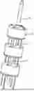
FIG. 1 is a schematic diagram illustrating an exemplary soft-actuated nozzle adjusting device according to some embodiments of the present disclosure;
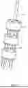
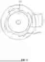
FIG. 2 is a schematic diagram illustrating a portion of the soft-actuated nozzle adjusting device according to some embodiments of the present disclosure;
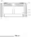
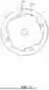
FIG. 3 is a schematic diagram illustrating an exemplary actuated joint according to some embodiments of the present disclosure;
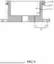
FIG. 4 is a schematic diagram illustrating another actuated joint according to some embodiments of the present disclosure;
FIG. 5 is a schematic diagram illustrating a moving body according to some embodiments of the present disclosure;
FIG. 6 is a schematic diagram illustrating a base body according to some embodiments of the present disclosure;
FIG. 7 is a schematic diagram illustrating another view of the moving body according to some embodiments of the present disclosure;
FIG. 8 is a schematic diagram illustrating another view of the base body according to some embodiments of the present disclosure; and
FIG. 9 is a schematic diagram illustrating another actuated joint according to some embodiments of the present disclosure.
REFERENCE SIGNS
1, actuated joint; 11, base body; 111, guiding section; 112, exposed section; 113, installation cavity; 114, limiting portion; 12, moving body; 121, receiving cavity; 122, blocking portion; 123, passage opening; 124, fixing bracket; 125, fixing tube; 126, clamp; 13, actuator element; 131, electromagnet; 132, mating piece; 133, elastic portion; 134, first electromagnet; 135, second electromagnet; 2, soft connecting sleeve; 3, nozzle; 4, abrasive hose; 5, soft connecting sleeve.
DETAILED DESCRIPTION
To more clearly illustrate the technical solutions related to the embodiments of the present disclosure, a brief introduction of the drawings referred to the description of the embodiments is provided below. Obviously, the drawings described below are only some examples or embodiments of the present disclosure. Those having ordinary skills in the art, without further creative efforts, may apply the present disclosure to other similar scenarios according to these drawings. Unless obviously obtained from the context or the context illustrates otherwise, the same numeral in the drawings refers to the same structure or operation.
As shown in the present disclosure and claims, the words “one”, “a”, “a kind” and/or “the” are not especially singular but may include the plural unless the context expressly suggests otherwise. In general, the terms “comprise”, “comprises”, “comprising”, “include”, “includes”, and/or “including”, merely prompt to include operations and elements that have been clearly identified, and these operations and elements do not constitute an exclusive listing. The methods or devices may also include other operations or elements.
Many specific details are set forth in the following description in order to facilitate a full understanding of the present disclosure, but the present disclosure may be implemented in other ways than those described herein. Therefore, the scope of protection of the present disclosure is not limited by the specific embodiments disclosed below. It should be noted that the embodiments of the present disclosure and the features in each embodiment may be combined without conflict.
In addition, in the description of the present disclosure, it is to be understood that the terms “top”, “bottom”, “inside”, “outside”, “axial”, “radial”, “circumferential”, or the like, indicate orientations or positional relationships according to the accompanying drawings, which are intended only to facilitate and simplify the description of the present disclosure, and do not indicate or imply that the device or element referred to must have a particular orientation and be constructed and operated with a particular orientation, and therefore are not to be construed as a limitation of the present disclosure.
It will be understood that unless otherwise expressly specified and qualified, the terms “on”, “connected”, “fixed”, “coupled”, etc., are to be understood in a broad sense, e.g., as a fixed connection, a removable connection, or as a single unit; as a mechanical connection, an electrical connection, or a communication; as a direct connection, an indirect connection through an intermediate medium, or as a connection between two devices, or as an indirect connection through an intermediate medium, and can be a connectivity within the two elements or an interactive relationship between the two elements. To one of the ordinary skill in the art, the specific meaning of the above terms in the present disclosure may be understood on a case-by-case basis.
In the present disclosure, unless otherwise expressly provided and limited, the first feature “over” or “under” the second feature may indicate a direct contact between the first and second features or an indirect contact between the first and second features through an intermediate medium. Moreover, certain terminology has been used to describe embodiments of the present disclosure. For example, the terms “one embodiment”, “an embodiment”, and/or “some embodiments” mean that a particular feature, structure, or characteristic described in connection with the embodiment is in at least one embodiment of the present disclosure. Therefore, it is emphasized and should be appreciated that two or more references to “an embodiment”, or “one embodiment”, or “an alternative embodiment” in various portions of the present disclosure are not necessarily all referring to the same embodiment. Furthermore, the particular features, structures, or characteristics may be combined as suitable in one or more embodiments of the present disclosure.
FIG. 1 is a schematic diagram illustrating an exemplary soft-actuated nozzle adjusting device according to some embodiments of the present disclosure. FIG. 2 is a schematic diagram illustrating a portion of the soft-actuated nozzle adjusting device according to some embodiments of the present disclosure.
Referring to FIGS. 1 and 2, the embodiments of the present disclosure provide a soft-actuated nozzle adjusting device for abrasive water jet polishing, including an actuated joint 1, a soft connecting sleeve 2, a nozzle 3, an abrasive hose 4, and a soft adjusting filament 5. At least two actuated joints 1 are provided, each actuated joint including a base body 11, a moving body 12, and an actuator element 13 (see FIG. 3) configured to drive the moving body 12 in a direction proximate to or away from the base body 11. A soft connecting sleeve 2 is provided between two adjacent actuated joints 1, and two ends of the soft connecting sleeve 2 are fixedly connected to the base body 11 and the moving body 12, respectively. A nozzle 3 is detachably connected to the moving body 12 at an end and follows the moving body 12 that is located at an end. An abrasive hose 4 is threaded through the soft connecting sleeve 2 and the actuated joints 1, and one end of the abrasive hose 4 is disposed in connection with the nozzle 3; a plurality of the soft adjusting filament 5 is provided along a circumferential direction of the actuated joints 1, and each of the soft adjusting filament 5 has a stop end stop-fitting with the moving body 12 that is located at the end.
The actuated joint 1 refers to a structure for driving the nozzle 3. The base body 11 refers to a fixed portion of the actuated joint 1, and the moving body 12 refers to a motion portion of the actuated joint 1.
The soft connecting sleeve 2 refers to a connecting sleeve for connecting adjacent actuated joints 1. The nozzle 3 refers to a structure for adjusting the flow velocity, flow rate, and injection direction of the polishing slurry. The abrasive hose 4 refers to a hose for conveying the polishing slurry with abrasive to the nozzle 3. The soft adjusting filament 5 refers to a structure for adjusting the direction of drive.
It should be noted that “two ends of the soft connecting sleeve 2 are fixedly connected to the base body 11 and the moving body 12, respectively” described above indicates that a plurality of actuated joints 1 are set up in sequence, such that the moving body 12 of one actuated joint 1 of two adjacent actuated joints 1 is provided opposite to the base body 11 of the other actuated joint 1 and two ends of the soft connecting sleeve 2 are connected to the moving body 12 and the base body 11 that are oppositely provided on the two adjacent actuated joints 1, respectively, so that motion strokes of a plurality of moving bodies 12 can be superimposed, thereby increasing an adjustable range of the nozzle 3. In the present disclosure, the term “moving body 12 that is located at the end” indicates that, among the plurality of the moving bodies 12, the one that deviates from the direction of the base body 11 does not have the actuated joint 1, and the term “the base body 11 that is located at the end” indicates that, among the plurality of base bodies 11, the one that deviates from the direction of the moving body 12 does not have the actuated joint 1.
When a cavity is polished using the soft-actuated nozzle adjusting device of the present disclosure, a suitable count of the actuated joint 1 is first selected according to a length of the cavity, and then the soft-actuated nozzle adjusting device is assembled according to the selected count of actuated joint 1 so that the nozzle 3 is provided to the moving body 12 that is located at the end. One end of the abrasive hose 4 is connected to the nozzle 3, then the end of the soft adjusting filament 5 away from the stop end is connected to rewinding equipment, the other end of the abrasive hose 4 is connected to abrasive supplying equipment, and the base body 11 that is located at the end is connected to the abrasive supplying equipment or the rewinding equipment, so as to cause the abrasive supplying equipment or the rewinding equipment to support the base body 11 that is located at the end. Then the soft-actuated nozzle adjusting device is extended into the cavity to be polished. When the soft-actuated nozzle adjusting device is extended into the cavity, the rewinding equipment rewinds the soft adjusting filament 5 on the corresponding side according to the shape of the cavity, and the two adjacent actuated joints 1 are moved relative to each other under the action of the soft adjusting filament 5, so that an angle is formed between the two adjacent actuated joints 1 that is matched to the cavity, thereby causing the nozzle 3 to move to the desired polishing position of the cavity. When the nozzle 3 moves to the position where the cavity is to be polished, the abrasive supplying equipment transports the polishing slurry to the abrasive hose 4, so that the polishing slurry is ejected from the nozzle 3 after passing through the abrasive hose 4, to realize the polishing operation of the cavity.
When the polishing position is adjusted, the actuator element 13 is started, and the actuator element 13 drives the moving body 12, so that the moving body 12 is moved relative to the base body 11 and the moving body 12 drives the nozzle 3 to the next position to be polished. This process does not require staff operation, the whole process is automated, thereby improving the polishing efficiency of the cavity, reducing the workload of the staff, and at the same time, ensuring the accuracy of the adjustment of the position of the nozzle 3, thereby improving the polishing quality of the cavity.
When the soft adjusting filament 5 is rewound, the soft connecting sleeve 2 undergoes an elastic deformation under the action of the actuated joint 1 and bends toward the side where the rewound soft adjusting filament 5 is located. When the rewound soft adjusting filament 5 is unwound, the two adjacent actuated joints 1 may move toward the coaxial position under the action of the soft connecting sleeve 2. When the soft adjusting filament 5 on the other side is rewound, the soft connecting sleeve 2 may be bent toward the other side under the action of the actuated joints 1, and the two adjacent actuated joints 1 form an angle on the other side, to enable the soft-actuated nozzle adjusting device to move forward and carry out the polishing operation in the multi-curved cavity, and to carry out the adjustment of the nozzle 3 in the multi-curved cavity, which greatly improves the polishing efficiency and the polishing quality of the cavity, and also greatly reduces the difficulty of polishing the multi-curved cavity.
Additionally, since the nozzle 3 is detachably connected to the moving body 12 at the end, the nozzle 3 may be selected according to the shape of the cavity, thereby increasing the flexibility of the soft-actuated nozzle adjusting device and improving the polishing quality of the cavity by using the soft-actuated nozzle adjusting device.
FIG. 3 is a schematic diagram illustrating an exemplary actuated joint according to some embodiments of the present disclosure. FIG. 4 is a schematic diagram illustrating another actuated joint according to some embodiments of the present disclosure.
In some embodiments, the actuator element 13 includes an electromagnet 131 provided in one of the base body 11 and the moving body 12, a mating piece 132 provided in the other of the base body 11 and the moving body 12, and an elastic portion 133 provided between the base body 11 and the moving body 12. When the electromagnet 131 is in an energized state, the electromagnet 131 generates a magnetic suction force on the mating piece 132 to cause the moving body 12 to overcome the elasticity of the elastic portion 133 and move in a direction close to the base body 11.
Exemplarily, referring to FIG. 3, the electromagnet 131 is provided at a position of the base body 11 proximate to the moving body 12, the mating piece 132 is provided on a side of the moving body 12 back away from the base body 11, a portion of the base body 11 and the moving body 12 may be spaced between the electromagnet 131 and the mating piece 132. Such a setting may better protect the electromagnet 131 and reduce the risk of damage to the electromagnet 131.
Exemplarily, referring to FIG. 4, the electromagnet 131 is provided on a side of the base body 11 near the moving body 12, the mating piece 132 is provided on a side of the moving body 12 near the base body 11, and the electromagnet 131 and the mating piece 132 may be in direct contact. Such a setting may increase the magnetic attraction effect between the electromagnet 131 and the mating piece 132.
Exemplarily, in the setting of FIG. 3, the mating piece 132 may also be set on the side of the moving body 12 facing toward the base body 11, and in FIG. 3 and FIG. 4, a position of the electromagnet 131 may be exchanged with a position of the mating piece 132. The setting of the electromagnet 131 and the mating piece 132 is sufficient to realize the movement of the moving body 12 by energizing or de-energizing.
The elastic portion 133 refers to a component for resetting the moving body 12 by elastic force.
Exemplarily, when the electromagnet 131 is energized, the electromagnet 131 generates a magnetic field and produces a magnetic suction force on the mating piece 132, which then causes the moving body 12 to overcome the elastic force of the elastic portion 133 in a direction close to the base body 11. When the electromagnet 131 is de-energized, the electromagnet 131 loses the magnetic field and thus loses the magnetic suction force on the mating piece 132, so that the moving body 12 moves in a direction away from the base body 11 under the action of the elastic portion 133. When the moving body 12 moves in a direction close to the base body 11, and when the moving body 12 moves in a direction away from the base body 11, the nozzle 3 may be driven in an extension direction of the cavity, thus realizing the adjustment of the position of the nozzle 3. At the same time, by adjusting the current of the electromagnet 131, it is possible to adjust the magnitude of the magnetic suction force exerted by the electromagnet 131 on the mating piece 132, to realize the precise control and adjustment of the distance between the moving body 12 and the base body 11, thereby further improving the precision of adjusting the position of the nozzle 3 and further improving the polishing effect on the cavity.
In some embodiments, the mating piece 132 is a structure made of an iron material, which ensures that the mating piece 132 can be magnetically attracted to the electromagnet 131 when the electromagnet 131 is energized. In other embodiments, the mating piece 132 may also be a structure made of a ferromagnetic material such as cobalt, nickel, or the like.
FIG. 5 is a schematic diagram illustrating a moving body according to some embodiments of the present disclosure. FIG. 6 is a schematic diagram illustrating a base body according to some embodiments of the present disclosure.
In some embodiments, referring to FIGS. 5 and 6, the moving body 12 is provided with a receiving cavity 121 whose opening facing toward the base body 11, the base body 11 is provided with a guiding section 111 extending into the receiving cavity 121, the guiding section 111 is provided with an installation cavity 113 whose opening facing toward the moving body 12, and at least a portion of the elastic portion 133 is located in the installation cavity 113.
The receiving cavity 121 refers to a cavity for holding the guiding section 111 and guiding with the guiding section 111. The installation cavity 113 refers to a cavity for providing the elastic portion 133. It will be appreciated that the orientation of the opening of the receiving cavity 121 is reversed to the orientation of the opening of the installation cavity 113.
Exemplarily, during the relative movement of the moving body 12 and the base body 11, the guiding section 111 slides relative to a wall of the cavity of the receiving cavity 121, such that the fit of the guiding section 111 with the receiving cavity 121 may guide the movement of the moving body 12 to limit the direction of the movement of the moving body 12 and increase the stability of the movement of the moving body 12, and at the same time, ensure the efficiency and accuracy of the adjustment of the nozzle 3.
Since at least a portion of the elastic portion 133 is located in the installation cavity 113, the stability of the elastic portion 133 is increased, and at the same time, the elastic portion 133 and the side wall of the receiving cavity 121 are formed to avoid the elastic portion 133 from contacting the side wall of the receiving cavity 121 and affecting the relative movement of the moving body 12 and the base body 11, ensuring normal adjustment of the nozzle 3, and increasing the working stability of the soft-actuated nozzle adjusting device.
In some embodiments, referring to FIG. 6, the base body 11 further includes an exposed section 112 located outside the receiving cavity 121. When the elastic portion 133 is compressed to the limit position, the exposed section 112 is pressed against an end of the moving body 12 near the exposed section 112 to provide a stopping fit between the moving body 12 and the exposed section 112, thereby avoiding the deformation transition of the elastic portion 133 that affects the ability to deform again.
FIG. 7 is a schematic diagram illustrating another view of the moving body according to some embodiments of the present disclosure. FIG. 8 is a schematic diagram illustrating another view of the base body according to some embodiments of the present disclosure.
Exemplarily, referring to FIGS. 5-8, a blocking portion 122 is provided at the opening of the receiving cavity 121, a limiting portion 114 is provided at an end of the guiding section 111, and the limiting portion 114 may abut against the blocking portion 122 in an axial direction of the moving body 12. The axial direction of the moving body 12 refers to a direction in which the center axis of the moving body is located, with reference to the Y direction in FIG. 5.
It will be appreciated that the blocking portion 122 is provided in the interior of the receiving cavity 121, and the limiting portion 114 is provided in the exterior of the guiding section 111.
Exemplarily, after the electromagnet 131 is de-energized, the elastic portion 133 gradually resumes deformation, causing the moving body 12 to move in a direction away from the base body 11 under the action of the elastic portion 133. When the blocking portion 122 moves to a position where the limiting portion 114 is located, the blocking portion 122 abuts against the limiting portion 114, so that the moving body 12 cannot continue to move in the direction away from the base body 11, so as to limit a range of motion of the moving body 12, preventing the guiding section 111 from detaching from the receiving cavity 121 and causing the elastic portion 133 to be dislodged from the installation cavity 113, thus increasing the stability of the elastic portion 133. Furthermore, it is avoided that the guiding section 111 is unable to move into the receiving cavity 121 when the electromagnet 131 is energized again.
In some embodiments, referring to FIGS. 3, 5, and 6, the electromagnet 131 is provided on a side of the limiting portion 114 towards the opening of the receiving cavity 121, i.e., the electromagnet 131 is provided in the receiving cavity 121, greatly reduce the risk of the electromagnet 131 coming into contact with the liquid, thereby reducing the requirement for s waterproof performance of the electromagnet 131, and reducing a production cost of the soft-actuated nozzle adjusting device. At the same time, the occurrence of the cavity wall of the cavity to be polished scraping against the electromagnet 131 is avoided, reducing the risk of the electromagnet 131 being damaged, and thereby reducing the failure rate of the soft-actuated nozzle adjusting device. Furthermore, when the electromagnet 131 generates a magnetic suction force on the mating piece 132, the limiting portion 114 may block and support the electromagnet 131, reducing the requirement for the fixing strength of the electromagnet 131, and thus reducing the production difficulty of the soft-actuated nozzle adjusting device.
In some embodiments, the mating piece 132 is provided on a side of the moving body 12 back away from the receiving cavity 121, so that when the electromagnet 131 exerts magnetic suction on the mating piece 132, the moving body 12 may block and support the mating piece 132, which also greatly reduces the need for fixing strength of the mating piece 132 to further reduce the production difficulty of the soft-actuated nozzle adjusting device. At the same time, the mating piece 132 may also block the protection of the moving body 12 to a certain extent, to reduce the risk of damage to the moving body 12, thus ensuring the service life of the soft-actuated nozzle adjusting device.
Additionally, by setting the electromagnet 131 on the side of the limiting portion 114 toward the opening of the receiving cavity 121, and setting the mating piece 132 on the side of the moving body 12 back away from the receiving cavity 121, the distance between the electromagnet 131 and the mating piece 132 can also be greatly reduced to increase the magnetic attraction effect of the electromagnet 131 on the mating piece 132 when the electromagnet 131 is energized.
In other embodiments, the electromagnet 131 may also be provided on the side of the base body 11 back away from the moving body 12. Alternatively, the electromagnet 131 is provided on the side of the moving body 12 back away from the base body 11, and the mating piece 132 is provided on the side of the base body 11 back away from the moving body 12.
In some embodiments, referring to FIGS. 7 and 8, a plurality of limiting portions 114 are provided at intervals along a circumferential direction of the guiding section 111, a plurality of blocking portions 122 are provided at intervals along a circumferential direction of the receiving cavity 121, and a passage opening 123 for the limiting portion 114 to pass through is formed between two adjacent blocking portions 122. The circumferential direction of the guiding section 111 refers to a circumferential direction around a central axis of the guiding section 111 (i.e., an axis corresponding to the center of the circle in FIG. 8).
In other words, the limiting portions 114 and the blocking portions 122 are of a block structure to reduce production costs of the base body 11 and the moving body 12.
Exemplarily, when assembling the moving body 12 and the base body 11 together, the limiting portion 114 is first aligned with the passage opening 123, then the moving body 12 or the base body 11 is pressed to cause the limiting portion 114 to enter the receiving cavity 121 through the passage opening 123. Then, the moving body 12 or the base body 11 is rotated so that the limiting portion 114 is misaligned with the passage opening 123 and has an overlapping portion with the blocking portion 122, so as to assemble the moving body 12 and the base body 11 together, greatly reducing the difficulty of assembling the moving body 12 and the base body 11 together, thereby increasing the productivity of the soft-actuated nozzle adjusting device. After the soft adjusting filament 5 is threaded through the moving body 12 and the base body 11, the soft adjusting filament 5 may limit the moving body 12 and the base body 11, which may prevent the moving body 12 and the base body 11 from rotating relative to each other, thereby avoiding alignment between the limiting portion 114 and the passage opening 123. Consequently, it eliminates the risk that the moving body 12 may separate from the base body 11 during the operation of the soft-actuated nozzle adjusting device.
In some other embodiments, the limiting portion 114 may also be an annular structure encircling the guiding section 111, and the blocking portion 122 may be a screw or rod structure threaded through the moving body 12.
In some embodiments, referring to FIG. 3, the base body 11 and the moving body 12 are respectively provided with a fixing bracket 124 configured to fix two ends of the elastic portion 133, so that the two ends of the elastic portion 133 are fixedly connected to the base body 11 and the moving body 12, respectively. On the one hand, the stability of the connection between the base body 11 and the moving body 12 is increased, and on the other hand, the fixing bracket 124 may restrain the elastic portion 133 in order to increase the stability of the elastic portion 133 as well as to ensure the elastic driving effect of the elastic portion 133 on the moving body 12.
In some embodiments, referring to FIG. 4, the base body 11 and the moving body 12 are hemispherical structures, and the base body 11 and the moving body 12 are provided with placement cavities relative to each other. One end of the elastic portion 133 is located in the placement cavity of the base body 11, and the other end of the elastic portion 133 is located in the placement cavity of the base body 11, so as to reduce the friction between the actuated joint 1 and the cavity to be polished, and at the same time to avoid the occurrence of the actuated joint 1 being stuck with an inner wall of the cavity, so as to ensure the smoothness of the actuated joint 1 when entering or exiting the cavity.
In some embodiments, the opposite end surfaces of the base body 11 and the moving body 12 are relatively provided with holding grooves, and the electromagnet 131 and the mating piece 132 are provided in two holding grooves respectively, so as to reduce the distance between the electromagnet 131 and the mating piece 132, thereby increasing the magnetic attraction effect of the electromagnet 131 on the mating piece 132.
In some embodiments, the elastic portion 133 is a spring to reduce the production cost of the soft-actuated nozzle adjusting device, as well as to ensure the elastic actuation effect of the elastic portion 133 on the moving body 12. In other embodiments, the elastic portion 133 may also be an elastic sheet or an elastic post, etc., or other elastic structures.
FIG. 9 is a schematic diagram illustrating another structure of the actuated joints according to some embodiments of the present disclosure.
In some embodiments, referring to FIG. 9, the actuator element 13 includes a first electromagnet 134 and a second electromagnet 135 provided opposite to each other, the first electromagnet 134 and the second electromagnet 135 are provided in the base body 11 and the moving body 12, respectively, and the first electromagnet 134 and the second electromagnet 135 include a first energized state of repulsion and a second energized state of attraction, respectively.
Exemplarily, in the first energized state, the first electromagnet 134 and the second electromagnet 135 generate a mutually repulsive force such that the moving body 12, under an action of the first electromagnet 134 and the second electromagnet 135, moves in a direction away from the base body 11. In the second energized state, the first electromagnet 134 and the second electromagnet 135 generate a mutually attractive force such that the moving body 12, under the action of the first electromagnet 134 and the second electromagnet 135, moves in a direction proximate to the base body 11, so as to achieve movement of the moving body 12 in a direction proximate to or away from the base body 11. In addition, by adjusting currents of the first electromagnet 134 and the second electromagnet 135, it is possible to realize the adjustment of the size of the magnetic suction force or the size of the magnetic repulsion force between the first electromagnet 134 and the second electromagnet 135, thus realizing a precise control of the distance of movement of the moving body 12, thereby realizing the precise adjustment of the position of the nozzle 3.
It should be noted that, in the first energized state, both first electromagnet 134 and second electromagnet 135 generate a magnetic field, and the first electromagnet 134 and the second electromagnet 135 are set up with the same poles opposite to each other so that the first electromagnet 134 and the second electromagnet 135 repel. In the second energized state, both first electromagnet 134 and second electromagnet 135 generate a magnetic field, and the first electromagnet 134 and the second electromagnet 135 are set up with the opposite magnetic poles opposite to each other so as to cause the first electromagnet 134 and the second electromagnet 135 to attract.
The setting manner of the first electromagnet 134 and the second electromagnet 135, reference may be referred to FIGS. 3, 5, and 6, and to the foregoing description regarding the setting manner of the electromagnet 131 and the mating piece 132.
In some embodiments, referring to FIG. 2, the moving body 12 that is located at the end is provided with a fixing tube 125, the nozzle 3 is threadedly connected to an outer end of the fixing tube 125, thereby decreasing the difficulty of replacing the nozzle 3 to improve the replacement efficiency the nozzle 3, while increasing the stability of the connection between the nozzle 3 and the moving body 12. The abrasive hose 4 is connected to an inner end of the fixing tube 125.
In some embodiments, one end of the abrasive hose 4 is set on the outside of the fixing tube 125 to connect the abrasive hose 4 and the fixing tube 125. The abrasive hose 4 is provided with a clamp 126 on the outside of the abrasive hose 4, and the clamp 126 is capable of applying a force to the abrasive hose 4 against the fixing tube 125 to increase the stability of the abrasive hose 4 and the fixing tube 125, while facilitating replacement of the abrasive hose 4.
In some embodiments, the stop end is formed as a block structure provided at the end of the soft adjusting filament 5, which reduces the difficulty of producing the soft adjusting filament 5. In other embodiments, the stop end may be formed as a rod-like structure provided at the end of the soft adjusting filament 5.
In some embodiments, the soft adjusting filament 5 is a steel wire threaded through the moving body 12 and the base body 11 to ensure the adjustability of the actuated joint 1. In other embodiments, the soft adjusting filament 5 may also be a structure made of other materials having flexibility.
In some embodiments, the soft connecting sleeve 2 is a hose. In other embodiments, the soft connecting sleeve 2 may also be a corrugated tube.
It will be appreciated that the base body 11 and the moving body 12 in the present disclosure are made of a material that is not ferromagnetic, such as plastic, aluminum material, or the like.
The present disclosure also provides a manner for using the above-described soft-actuated nozzle adjusting device, including following operations.
In S1, a count of actuated joints 1 is determined and a suitable nozzle 3 is selected.
In S2, the soft-actuated nozzle adjusting device is assembled. The soft-actuated nozzle adjusting device is assembled according to the selected count of actuated joints 1, and the selected nozzle 3 is mounted to the moving body 12 that is located at the end, i.e., the nozzle 3 is threadedly connected to the fixing tube 125.
In S3, the abrasive supplying equipment and the rewinding equipment are connected. The end of the abrasive hose 4 away from the nozzle 3 is connected to the abrasive supplying equipment, and the soft adjusting filament 5 is connected to the rewinding equipment, so that the rewinding equipment can wind or unwind the soft adjusting filament 5, and the abrasive supplying equipment may transport the polishing slurry into the abrasive hose 4 and dispense it through the nozzle 3.
In S4, the soft-actuated nozzle adjusting device is extended into the cavity. The soft-actuated nozzle adjusting device is extended into the cavity, and the soft adjusting filament 5 is rewound by the rewinding equipment during the extension operation, so as to form a pinch angle between the two adjacent actuated joints 1 to match the shape of the cavity, so that the nozzle 3 moves to the position to be polished, then the abrasive supplying equipment delivers the polishing slurry into the abrasive hose 4, so as to cause the polishing slurry to be shot through the nozzle 3 to the position to be polished.
In S5, the nozzle 3 is adjusted. While the position to be polished is adjusted, the actuator element 13 is started to adjust the distance between the actuator element 13 to the base body 11 and the moving body 12, so that the moving body 12 drives the movement of the nozzle 3 and realizes the adjustment of the nozzle 3.
By utilizing the above-described manner for using the soft-actuated nozzle adjusting device to polish the cavity, the operations of polishing the cavity are simplified, the time required to polish the cavity is shortened, and the polishing efficiency of the cavity is improved. At the same time, the position of the nozzle 3 can be precisely adjusted, thereby improving the polishing quality of the cavity.
By utilizing the above-described technical manner, the soft-actuated nozzle adjusting device provided by the embodiments of the present disclosure includes but is not limited to the following beneficial effects.
First, the soft-actuated nozzle adjusting device of the present disclosure includes the actuated joint, the soft connecting sleeve, the nozzle, the abrasive hose, and the soft connecting sleeve. At least two actuated joints are arranged, each actuated joint includes the base body, the moving body, and the actuator element configured to drive the moving body in a direction proximate to or away from the base body. A soft connecting sleeve is provided between two adjacent actuated joints, and two ends of the soft connecting sleeve are fixedly connected to the base body and the moving body, respectively. The nozzle is detachably connected to the moving body that is located at the end and follows the moving body that is located at the end. The abrasive hose is threaded through the soft connecting sleeve and the actuated joint, and one end of the abrasive hose is provided in connection with the nozzle. The plurality of soft connecting filaments are provided along the circumferential direction along the actuated joint, each soft adjusting filament being threaded through a plurality of actuated joints, and each soft adjusting filament having the stop end that abuts against the moving body that is located at the end. Therefore, the whole process of polishing the cavity is carried out without the need for staff, and the whole process is automatically operated, thus improving the polishing efficiency of the cavity, reducing the workload of the staff, and at the same time guaranteeing the accuracy of the adjustment of the nozzle position, thereby improving the polishing quality of the cavity.
Second, the actuator element in the present disclosure includes the electromagnet provided in one of the base body and the moving body, the mating piece provided in the other of the base body and the moving body with ferromagnetism in character, and the elastic portion provided between the base body and the moving body. When the electromagnet is in the energized state, the electromagnet generates the magnetic suction force on the mating piece to cause the moving body to overcome the elasticity of the elastic portion and move in the direction close to the base body, thereby realizing the adjustment of the position of the nozzle. At the same time, it is also possible to realize the regulation of the magnitude of the magnetic suction force that the electromagnet is able to exert on the mating piece by regulating the current of the electromagnet, thereby realizing the precise control and adjustment of the distance between the moving body and the base body, thus further improving the precision of the adjustment of the position of the nozzle, and further improving the polishing effect of the cavity.
Third, the moving body in the present disclosure is provided with the receiving cavity whose opening faces toward the base body, the base body is provided with the guiding section extending into the receiving cavity, which in turn allows the guiding section and the receiving cavity to be coordinated to guide the moving body to limit the direction of motion of the moving body and increase the stability of the moving body, and at the same time, ensures the adjustment efficiency and accuracy of the nozzle. The guiding section is provided with the installation cavity whose opening facing toward the moving body, and at least a portion of the elastic portion is located in the installation cavity, thereby increasing the stability of the elastic portion, and at the same time making the elastic portion and the side wall of the installation cavity form an avoidance. Thus, the elastic portion is avoided from contacting with the side wall of the installation cavity, which affects the relative movement of the moving body and the base body, thereby ensuring the normal adjustment of the nozzle and increasing the stability of the soft-actuated nozzle adjusting device.
Anything not described in the present disclosure can be realized by adopting or borrowing existing technology.
Each embodiment in the present disclosure is described in a progressive manner, and it is sufficient to refer to each embodiment for the same and similar parts of each embodiment to each other, and each embodiment focuses on the differences with other embodiments.
The above description is only an example of the embodiments of the present disclosure and is not intended to limit the present disclosure. The present disclosure is subject to various changes and variations for those skilled in the art. Any modifications, equivalent substitutions, improvements, etc., which are made within the spirit and principles of the present disclosure shall be included within the scope of the claims of the present disclosure.
Each of the patents, patent applications, publications of patent applications, and other material, such as articles, books, specifications, publications, documents, things, and/or the like, referenced herein is hereby incorporated herein by this reference in its entirety for all purposes. History application documents that are inconsistent or conflictive with the contents of the present disclosure are excluded, as well as documents (currently or subsequently appended to the present specification) limiting the broadest scope of the claims of the present disclosure. By way of example, should there be any inconsistency or conflict between the description, definition, and/or the use of a term associated with any of the incorporated material and that associated with the present document, the description, definition, and/or the use of the term in the present document shall prevail.
Claims
What is claimed is:1. A soft-actuated nozzle adjusting device for abrasive water jet polishing, comprising:
an actuated joint, at least two actuated joints being arranged, each actuated joint including a base body, a moving body, and an actuator element configured to drive the moving body in a direction proximate to or away from the base body;
a soft connecting sleeve provided between two adjacent actuated joints, and two ends of the soft connecting sleeve being fixedly connected to the base body and the moving body, respectively;
a nozzle detachably connected to the moving body that is located at an end and follows the moving body that is located at the end to move;
an abrasive hose threaded through the soft connecting sleeve and the actuated joint, and one end of the abrasive hose being provided in connection with the nozzle; and
a plurality of soft adjusting filaments provided along a circumferential direction of the actuated joint, each soft adjusting filament being threaded through a plurality of actuated joints, and each soft adjusting filament having a stop end that abuts against the moving body that is located at the end, wherein
the actuator element includes an electromagnet provided in one of the base body and the moving body, a mating piece provided in the other of the base body and the moving body with ferromagnetic in character, and an elastic portion provided between the base body and the moving body, and when the electromagnet is in an energized state, the electromagnet generates a magnetic suction force on the mating piece to cause the moving body to overcome an elasticity of the elastic portion and move in a direction close to the base body.
2. The soft-actuated nozzle adjusting device according to claim 1, wherein the moving body is provided with a receiving cavity whose opening faces toward the base body, the base body is provided with a guiding section extending into the receiving cavity, the guiding section is provided with an installation cavity whose opening faces toward the moving body, and at least a portion of the elastic portion is located in the installation cavity.
3. The soft-actuated nozzle adjusting device according to claim 2, wherein a blocking portion is provided at the opening of the receiving cavity, a limiting portion is provided at an end of the guiding section, and the limiting portion is able to abut against the blocking portion in an axial direction of the moving body.
4. The soft-actuated nozzle adjusting device according to claim 3, wherein the electromagnet is provided on a side of the limiting portion towards the opening of the receiving cavity, and the mating piece is provided on a side of the moving body back away from the receiving cavity.
5. The soft-actuated nozzle adjusting device according to claim 3, wherein a plurality of limiting portions are provided at intervals along a circumferential direction of the guiding section, a plurality of blocking portions are provided at intervals along a circumferential direction of the receiving cavity, and a passage opening for the limiting portion to pass through is formed between two adjacent blocking portions.
6. The soft-actuated nozzle adjusting device according to claim 1, wherein the base body and the moving body are respectively provided with a fixing bracket configured to fix an end of the elastic portion.
7. The soft-actuated nozzle adjusting device according to claim 1, wherein the actuator element includes a first electromagnet and a second electromagnet provided opposite to each other, the first electromagnet and the second electromagnet are provided in the base body and the moving body, respectively, and the first electromagnet and the second electromagnet include a first energized state of repulsion and a second energized state of attraction, respectively.
8. The soft-actuated nozzle adjusting device according to claim 1, wherein the moving body that is located at the end is provided with a fixing tube, the nozzle is threadedly connected to an outer end of the fixing tube, and the abrasive hose is connected to an inner end of the fixing tube.
Images & Drawings included:


Sources:
- United States Patent and Trademark Office - verify current appl. status at the USPTO↗
Recent applications in this class:
- » 20250282025 2025-09-11
MODULAR FLAT WETBLAST NOZZLE - » 20250187143 2025-06-12
ROTATABLE CARRIER ASSEMBLY AND RELATED SYSTEMS AND METHODS - » 20240100651 2024-03-28
ABRASIVE WATERJET CUTTING NOZZLE WITH A RESISTIVE STRAIN GAUGE SENSOR - » 20240025016 2024-01-25
SILENCER FOR A BLAST NOZZLE - » 20240009806 2024-01-11
THRUST REDUCTION SYSTEM FOR A BLAST NOZZLE - » 20240009805 2024-01-11
Spray Head Device and Sandblasting Device for Automobile Part Processing - » 20240001509 2024-01-04
DAMAGE TOLERANT CAVITATION NOZZLE - » 20230330813 2023-10-19
ABRASIVE WATER JET NOZZLE FOR STRENGTHENING - » 20230286109 2023-09-14
AN IMPROVED BLAST NOZZLE - » 20230150089 2023-05-18
FOCUSING TUBE, AND USE THEREOF
Recent applications for this Assignee:
- » 20260106442 2026-04-16
BROADBAND INTELLIGENT VIBRATION DAMPER FOR POWER TRANSMISSION LINES AND OPTIMIZATION DESIGN METHOD THEREFOR - » 20260103981 2026-04-16
PRESSURE-CONTROLLED TUNNEL DIRECTIONAL GROUTING-BASED REINFORCEMENT DEVICES - » 20260086151 2026-03-26
RAPID PREDICTION METHOD AND SYSTEM FOR COMMUTATION FAILURE IN HVDC BASED ON COMMUTATION FAILURE RISK FACTOR - » 20260075429 2026-03-12
RADIO FREQUENCY FINGERPRINTING METHOD AND SYSTEM BASED ON CONVOLUTION-ATTENTION MECHANISM AND MULTI-PACKET INFERENCE - » 20260074604 2026-03-12
Non-circulating-current phase-shift control method for dual active bridge converter - » 20260037699 2026-02-05
METHOD FOR DESIGING CAPACITY OF COMPRESSED GAS ENERGY STORAGE SYSTEM - » 20260029290 2026-01-29
METHOD, APPARATUS AND SYSTEM FOR TESTING INERTIA COEFFICIENT AND DAMPING COEFFICIENT OF GRID-FORMING CONVERTER - » 20260028453 2026-01-29
FLUOROSILICONE RAW RUBBER WITH HIGH ISOTACTICITY AND PREPARATION METHOD THEREFOR, AND HIGH-STRENGTH OIL-RESISTANT FLUOROSILICONE SEALING MATERIAL FOR ENGINE AND PREPARATION METHOD THEREFOR - » 20260009829 2026-01-08
METHOD, DEVICE, APPARATUS, AND STORAGE MEDIUM FOR DETERMINING OVERLOAD BOUNDARY OF MMC - » 20260009444 2026-01-08
NEGATIVE POISSON'S RATIO VIBRATION ABSORBING BASE AND MILLING DEVICE FOR MILLING THIN-WALLED PARTS