APPARATUS FOR MOUNTING A LINER COMPRISING A LINER DISCHARGE COMPONENT TO A CONTAINER
US20260109534A1
2026-04-23
19/364,747
2025-10-21
Smart Summary: A new device helps attach a liner to a container that has a solid outer wall and a space inside. The container has a discharge nipple at the bottom that connects to this space. The device includes a liner discharge fitment with openings for input and output, along with a flange that fits securely around the output opening. It also has a nipple adapter and an elbow adapter, both of which have their own openings and seats for proper connection. The flange of the fitment is designed to sit firmly against the seats of both adapters, ensuring a secure and efficient setup. 🚀 TL;DR
Abstract:
Apparatus for mounting a liner to a container comprising a rigid outer wall, a top surface, and a bottom surface defining a cavity, the container further comprising a discharge nipple formed in the bottom surface and fluidically connected to the cavity, the apparatus comprising: a liner discharge fitment comprising a discharge fitment input opening, a discharge fitment output opening and a passageway extending therethrough, wherein a radially extending flange extends about a perimeter of the discharge fitment output opening; and a discharge element comprising: a nipple adapter comprising a nipple adapter body having a nipple adapter input opening, a nipple adapter output opening and a nipple adapter central lumen extending therebetween, and further wherein the nipple adapter body comprises a nipple adapter seat; and an elbow adapter comprising an elbow adapter body having an elbow adapter input opening, an elbow adapter output opening and an elbow adapter passageway extending therebetween, wherein the elbow adapter body comprises an elbow adapter seat; wherein the flange of the liner discharge fitment is configured to be seated against (i) the nipple adapter seat, and (ii) the elbow adapter seat.
Inventors:
- Joseph Sullivan 12 🇺🇸 Plymouth, MA, United States
- John Buchenan 1 🇺🇸 Winchendon, MA, United States
Applicant:
Interested in similar patents?
Get notified when new applications in this technology area are published.
Classification:
B65D88/54 » CPC main
Large containers characterised by means facilitating filling or emptying
B65D2588/125 » CPC further
Large container rigid specially adapted for transport Intermediate bulk container [IBC]
Description
REFERENCE TO PENDING PRIOR PATENT APPLICATION
This patent application claims benefit of pending prior U.S. Provisional Patent Application Ser. No. 63/709,610, filed Oct. 21, 2024 by CDF Corporation and Joseph Sullivan et al. for APPARATUS FOR MOUNTING A LINER COMPRISING A LINER DISCHARGE COMPONENT TO A CONTAINER (Attorney's Docket No.: CDF-4 PROV).
The above-identified patent application is hereby incorporated herein by reference.
FIELD OF THE INVENTION
This invention relates to containers and liners for lining containers in general, and more particularly to a novel discharge component for facilitating the mounting of a liner comprising a liner discharge component to a container.
BACKGROUND OF THE INVENTION
Containers, specifically rigid intermediate bulk containers (IBCs) are widely used in industry for storing liquids (e.g., chemicals, food stuffs, etc.). In order to maximize storage capacity and to facilitate vertical storage (i.e., stacking) of containers, IBCs are frequently manufactured in standardized sizes (e.g., to fit in existing warehouse space, to be movable via forklift/crane, etc.). Thus, thousands of standard-sized IBCs exist in industry today.
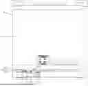
By way of example but not limitation, and looking now at FIG. 1, there is shown a generally rectangular IBC 5 of the sort known in the container arts. IBC 5 generally comprises a rigid outer wall 10, a top surface 15, and a bottom surface 20. Outer wall 10, top surface 15, and bottom surface 20 collectively enclose a cavity 25 for storing a liquid.
A top access port 30 is formed in top surface 15 of IBC 5 to permit access to cavity 25. A two inch (2″) NPT standardized, National Pipe Thread (NPT) discharge nipple 35 fluidically connected to cavity 25 is welded to bottom surface 20 of IBC 5 to permit selective discharge of the contents of cavity 25, as will hereinafter be discussed in further detail.
IBC 5 is typically provided with a plurality of legs 40 (e.g., four legs) disposed at the corners of IBC 5 which slightly raise cavity 25 of IBC 5 above the surface (e.g., the floor) upon which IBC 5 is disposed so that discharge nipple 35 can be accessed. In order to maximize the size of cavity 25 (and hence, the volume capacity of IBC 5), legs 40 typically extend only a very short distance (e.g., approximately 6 inches) from bottom surface 20 of IBC 5 to the surface (e.g., the floor) upon which IBC 5 is placed, providing a small gap 45 between bottom surface 20 and the floor.
It is known in the container arts to mount a discharge element 50 to discharge nipple 35 to permit selective discharge of material contained in cavity 25 through discharge element 50, as will hereinafter be discussed in further detail.
More particularly, and looking now at FIG. 2, prior art discharge element 50 generally comprises a standard 2 inch, 90 degree NPT elbow 55 mounted to discharge nipple 35 (e.g., by threading an end of elbow 55 onto discharge nipple 35), a 2 inch pipe nipple 60 mounted to the free end of elbow 55, and a 2 inch ball valve 65 mounted to the free end of pipe nipple 60. A user can selectively discharge the contents of cavity 25 of IBC 5 via discharge element 50 by opening ball valve 65, whereby to cause the contents of cavity 25 of IBC 5 to flow out discharge nipple 35, and through discharge element 50.
While the foregoing prior art discharge element 50 works to provide IBCs in which the contents can be selectively discharged, there are significant drawbacks to these prior art systems.
Specifically, in many applications, a user may desire to maintain the cleanliness/sterility of the contents of cavity 25 of IBC 5, (e.g., if the IBC is to contain food stuffs, pharmaceuticals, sensitive chemicals, etc.). Cavity 25 and/or discharge element 50 of IBC 5 are generally challenging to clean thoroughly and/or to sterilize, particularly in instances such as those present with discharge element 50 in which a fluid flows through, and contacts, a screw-and-thread connection (e.g., the interface of nipple 35 and elbow 55, the interface of elbow 55 and pipe nipple 60, and/or the interface between pipe nipple 60 and ball valve 65).
In practice, it is frequently necessary to completely disassemble discharge element 50 to effectively clean the components of discharge element 50. It can also be challenging to completely clean cavity 25 (e.g. via flushing the cavity, etc.) and even more challenging, if not impossible, to sterilize cavity 25 between applications of IBC 5. In order to address these limitations of IBC 5, it has been suggested that a disposable liner (e.g., in the form of a fluidically sealed bag) may be disposed within the interior of cavity 25 so as permit the end user to store liquids inside of the liner “bag” without allowing the liquid to contact the inner surface of outer wall 10 (and/or the inner surface of top surface 15, bottom surface, 20, etc.). When it is desired to re-use IBC 5, the user merely removes the liner from cavity 25 and replaces the liner with a new, unused liner. However, it has been found that it is extraordinarily difficult to provide a liner comprising an element that can be passed through the tortuous, confined pathway of discharge element 50 without exposing at least some of the components of discharge element 50 to contact with the material contained within the liner. Specifically, such systems generally require liners comprising an elaborate multi-part discharge structure that can be fed through the tortuous path of discharge element 50, making manufacture of the liner both more expensive and technically challenging. And it can be significantly challenging to pass an elaborate multi-part discharge structure mounted at one end to a liner disposed in cavity 25 through the tortuous path of discharge element 50 because gap 45 provides only a very limited workspace.
One significant issue is that existing IBCs 5 cannot be easily modified because of the very limited workspace provided by gap 45, and there are over 100,000 such IBCs currently in use in the United States. Hence, retrofitting existing IBCs is both expensive and technically challenging.
Thus there is a need for a new and improved discharge element that can be mounted to the existing discharge nipple 35 of an existing IBC 5, which can fit within the limited workspace provided by gap 45, and which can easily accommodate a novel one-piece liner discharge fitting in a manner that reduces the number of elements to be cleaned/sterilized when the discharge element/liner is removed and replaced, and which facilitates quick and easy removal and replacement of the liner.
SUMMARY OF THE INVENTION
The present invention comprises the provision and use of a new and improved discharge element that can be mounted to the existing discharge nipple 35 of an existing IBC 5, which can fit within the limited workspace provided by gap 45, and which can easily accommodate a novel one-piece liner discharge fitting in a manner that reduces the number of elements to be cleaned/sterilized when the discharge element/liner is removed and replaced, and which facilitates quick and easy removal and replacement of the liner.
In one preferred form of the invention, there is provided apparatus for mounting a liner to a container comprising a rigid outer wall, a top surface, and a bottom surface defining a cavity, the container further comprising a discharge nipple formed in the bottom surface and fluidically connected to the cavity, the apparatus comprising:
-
- a liner discharge fitment comprising a discharge fitment input opening, a discharge fitment output opening and a passageway extending therethrough, wherein a radially extending flange extends about a perimeter of the discharge fitment output opening; and
- a discharge element comprising:
- a nipple adapter comprising a nipple adapter body having a nipple adapter input opening, a nipple adapter output opening and a nipple adapter central lumen extending therebetween, and further wherein the nipple adapter body comprises a nipple adapter seat; and
- an elbow adapter comprising an elbow adapter body having an elbow adapter input opening, an elbow adapter output opening and an elbow adapter passageway extending therebetween, wherein the elbow adapter body comprises an elbow adapter seat;
- wherein the flange of the liner discharge fitment is configured to be seated against (i) the nipple adapter seat, and (ii) the elbow adapter seat.
In another preferred form of the invention, there is provided a method for mounting an adapter to a discharge nipple of a container comprising a rigid outer wall, a top surface, and a bottom surface defining a cavity, the method comprising:
-
- mounting a nipple adapter to the discharge nipple of the container, wherein the nipple adapter comprises a nipple adapter body having a nipple adapter input opening, a nipple adapter output opening and a nipple adapter central lumen extending therebetween, and wherein the nipple adapter body comprises a nipple adapter seat;
- disposing a liner discharge fitment comprising a discharge fitment input opening, a discharge fitment output opening and a passageway extending therethrough in the discharge nipple of the container such that a radially extending flange extending about a perimeter of the discharge fitment output opening is disposed against the nipple adapter seat; and
- mounting an elbow adapter comprising an elbow adapter input opening, an elbow adapter output opening and an elbow adapter passageway extending therebetween to the nipple adapter, wherein the elbow adapter body comprises an elbow adapter seat for engaging the flange of the liner discharge fitment against the nipple adapter seat.
In another preferred form of the invention, there is provided a discharge element for selectively discharging the contents of a container comprising an outer wall, a top surface, and a bottom surface defining a cavity, the container further comprising an outlet formed in the bottom surface and fluidically connected to the cavity, the discharge element comprising:
-
- a nipple adapter comprising a nipple adapter body having a nipple adapter input opening, a nipple adapter output opening and a nipple adapter central lumen extending therebetween, and further wherein the nipple adapter body comprises a nipple adapter seat; and
- an elbow adapter comprising an elbow adapter body having an elbow adapter input opening, an elbow adapter output opening and an elbow adapter passageway extending therebetween, wherein the elbow adapter body comprises an elbow adapter seat;
- a discharge fitment configured to be received in the nipple adapter central lumen, the discharge fitment comprising an inlet, an outlet, and a neck portion having a passageway extending therethrough, the neck portion extending through the nipple adapter central lumen and terminating at the outlet in a radially-extending outlet flange;
- wherein the flange of the discharge fitment is configured to be seated against (i) the nipple adapter seat, and (ii) the elbow adapter seat, whereby to form a fluidic seal between the nipple adapter output opening and the elbow adapter input opening.
BRIEF DESCRIPTION OF THE DRAWINGS
These and other objects and features of the present invention will be more fully disclosed or rendered obvious by the following detailed description of the preferred embodiments of the invention, which is to be considered together with the accompanying drawings wherein like numbers refer to like parts, and further wherein:
FIGS. 1 and 2 are schematic views showing a prior art intermediate bulk container (IBC) comprising a prior art discharge element;
FIG. 3 depicts a novel discharge element for attachment to a NPT discharge nipple;
FIG. 4 is a schematic view showing further details of the novel discharge element formed in accordance with the present invention;
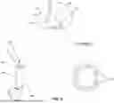
FIG. 5 is a schematic view showing a novel nipple adapter of the novel discharge element of FIGS. 3 and 4;
FIG. 6 is a schematic view showing a novel elbow adapter of the novel discharge element of FIGS. 3 and 4;
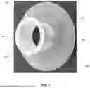
FIG. 7 is a schematic view showing a novel liner discharge fitment for use with the novel discharge element of FIGS. 3 and 4;
FIG. 7A is a schematic view showing a novel liner comprising the novel discharge fitment of FIG. 7 for use with an intermediate bulk container (IBC);
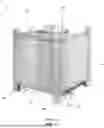
FIG. 8 is a schematic view showing the novel discharge element of FIGS. 3 and 4 mounted to an intermediate bulk container (IBC); and
FIG. 9 is a schematic view showing an IBC comprising a prior art discharge element and an IBC comprising the novel discharge element of FIGS. 3 and 4.
DETAILED DESCRIPTION OF THE PREFERRED EMBODIMENTS
The present invention comprises the provision and use of a new and improved discharge element that can be mounted to the existing discharge nipple 35 of an existing IBC 5, which can fit within the limited workspace provided by gap 45, and which can easily accommodate a novel one-piece liner discharge fitting in a manner that reduces the number of elements to be cleaned/sterilized when the discharge element/liner is removed and replaced, and which facilitates quick and easy removal and replacement of the liner.
More particularly, and looking now at FIGS. 3 and 4, there is shown a novel discharge element 105 formed in accordance with the present invention. Discharge element 105 generally comprises a nipple adapter 110, an elbow adapter 115, a ball valve 120, and a clamp ring 125. It will be appreciated that where ball valve 120 is formed as an element separate from elbow adapter 115 (see below), ball valve 120 may be identical to prior art ball valve 65. Novel discharge element 105 is configured to be mounted to an existing IBC 5 so as to accommodate a novel liner discharge fitting of a liner disposed in cavity 25 of IBC 5, as will hereinafter be discussed in further detail.
In one preferred embodiment of the invention, and looking now at FIG. 5, nipple adapter 110 comprises a circumferentially-extending sidewall 130 defining a central lumen 135 having an input opening 140 and an output opening 145. The output opening end of sidewall 130 defines a fitment engagement surface 147 for engaging a fitment of a liner, as will hereinafter be discussed in further detail. A thread 150 is formed on the inner surface of sidewall 130 so as to facilitate mounting of nipple adapter 110 to discharge nipple 35 of an IBC 5, as will hereinafter be discussed in further detail. A radially-extending flange 155 extends about the circumference of sidewall 130 so as to extend radially outboard therefrom. Flange 155 comprises an input-side-facing chamfer 160 and an output-side-facing seat 165 for mating with a counterpart flange formed on elbow adapter 115, as will hereinafter be discussed in further detail. If desired, one or more slots 170 may be formed in sidewall 130 and/or flange 155 to accommodate a spanner wrench, whereby to facilitate mounting of nipple adapter 110 to discharge nipple 35.
Looking now at FIG. 6, elbow adapter 115 comprises a body 175 defining a generally L-shaped passageway 180. Passageway 180 is characterized by an input opening 185 and an output opening 190. A flange 195 is formed on body 175 extending radially outboard of body 175 at input opening 185. Flange 195 comprises a counterbored, circumferentially-extending opening 200 having a diameter that is greater than the diameter of input opening 185. It will be appreciated that, as a result of forming flange 195 with counterbored, circumferentially-extending opening 200 in this manner, a circumferentially-extending seat 205 is provided which extends about the perimeter of opening 185. The output-side-facing side of flange 195 preferably comprises a chamfered surface 210 for facilitating mounting of clamp ring 125 to elbow adapter 115, as will hereinafter be discussed in further detail.
Body 175 of elbow adapter 115 preferably also comprises a thread 215 extending circumferentially about the outer surface of body 175 in the region of output opening 190 to facilitate mounting of ball valve 120 to elbow adapter 115, as will hereinafter be discussed in further detail. However, it should also be appreciated that, if desired, elbow adapter 115 and ball valve 120 may be formed as a single integral sub-assembly (in which case thread 215 may be omitted).
Alternatively, elbow adapter 115 and ball valve 120 may be formed as two separate elements that are permanently mounted together (e.g., welded together) to form a single integral sub-assembly.
Looking now at FIGS. 7 and 7A, there is shown a novel liner discharge fitment 220 formed in accordance with the present invention. Liner discharge fitment 220 is preferably formed out of a resilient, flexible material, and is configured to be mounted (e.g., heat-welded) to a liner 222 (FIG. 7A) sized to fit within cavity 25 of IBC 5 such that liner discharge fitment 220 is received within a portion of discharge element 105, as will hereinafter be discussed in further detail.
Liner discharge fitment 220 generally comprises a body 225 having a liner-mating, radially-extending flange 230 formed on a first end of body 225, a neck portion 235 extending generally perpendicular to flange 230, and a discharge element-mating, radially-extending flange 240 formed on a second end of body 225 opposite flange 230. As a result of this construction, a passageway 245 extends through the center of body 225. Liner 222 is formed out of a suitable material so as to be able to conform to the geometry of cavity 25 of IBC 5 when disposed within cavity 25 and filled, as will be apparent to one of skill in the art in view of the present disclosure. Neck portion 235 of liner discharge fitment 220 is sized to be received in, and pass through, discharge nipple 35 (e.g., a 2″ NPT standardized discharge nipple) of IBC 5, as will also be apparent to one of skill in the art in view of the present disclosure.
Looking now at FIGS. 4, 5, 7, 7A and 8, a liner 222 comprising liner discharge fitting 220 is disposed within cavity 25 of an IBC 5 (e.g., via accessing cavity 25 through access port 30) such that neck portion 235 and flange 240 of liner discharge fitting 220 extend through, and project out of, discharge nipple 35 of IBC 5 and through nipple adapter 110 mounted to discharge nipple 35 (FIG. 4).
To assemble discharge element 105 for use with linear discharge fitting 220 of liner 222 disposed within cavity 25 of IBC 5, nipple adapter 110 is first mounted to discharge nipple 35 of IBC 5 (e.g., by mating thread of nipple adapter 110 to a counterpart thread formed on the exterior of discharge nipple 35, as will be apparent to one of ordinary skill in the art in view of the present disclosure). It will be appreciated that the step of mounting nipple adapter 110 to discharge nipple 35 need only be performed one time in order to convert an existing IBC 5 for use with the novel discharge element of the present invention.
A ball valve 120 (e.g., a ball valve which may be identical to prior art ball valve 65) may be mounted to elbow adapter 115 (i.e., by threadingly engaging a thread formed on an interior surface of a passageway passing through ball valve 120 with thread 215 of elbow adapter 115, as will be apparent to one of ordinary skill in the art in view of the present disclosure), whereby to result in a semi-permanent sub-assembly. As discussed above, elbow adapter 115 and ball valve 120 may alternatively be formed as an integral sub-assembly, or as two separate pieces permanently mounted together as a sub-assembly.
Next, the sub-assembly of elbow adapter 115 and ball valve 120 is, in turn, mounted to nipple adapter 110 such that flange 240 of liner discharge fitting 220 is received in counterbored, circumferentially-extending opening 200 of elbow adapter 115 and sits flush within seat 205 extending about perimeter of input opening 185 of passageway 180 of elbow adapter 115.
It will be appreciated that as elbow adapter 115 is moved towards output opening 145 of nipple adapter 110, flange 240 of liner discharge fitment 220 is received by seat 205 within counterbored, circumferentially-extending opening 200. In this way, when elbow adapter 115 is mounted to nipple adapter 110, flange 240 is “pinched” between fitment-engaging surface 147 of nipple adapter 110 and seat 205 of elbow adapter 115 in the manner of a sealing gasket. A clamp ring 125 (e.g., a clamp ring of the sort known in the plumbing arts) is then passed around and over flange 155 of nipple adapter 110 and flange 195 of elbow adapter 115 so as to maintain the “pinching force” exerted on flange 240 of liner discharge fitting 220 and releasably mount elbow adapter 115 to nipple adapter 110.
When it is desired to remove discharge element 105 and/or liner discharge fitment 220 from IBC 5 (e.g., such as may be desired when removing the liner from cavity 25 of IBC 5), a user merely needs to remove clamp ring 125, whereupon flange 240 is released and the liner (and liner discharge fitment 220) may be removed from cavity 25 of IBC 5 via access port 30. It will be appreciated that in a preferred form of the invention, the combination of elbow adapter 115 and ball valve 120 constitute a single permanent (or semi-permanent) sub-assembly, facilitating easy removal of the portion of discharge element 105 that must be removed to install a new liner in an IBC 5 in the manner discussed above.
It will be appreciated that, as a result of the construction and arrangement of the elements of discharge element 105 and liner discharge fitment 220, no material contained within the liner comes into contact with any element of nipple adapter 110. Inasmuch as elbow adapter 115 and ball valve 120 have been exposed to material passed through passageway 245 of liner discharge fitment 220, elbow adapter 115 and ball valve 120 can be replaced (e.g., after cleaning) for use with a new liner comprising a new liner discharge fitment 220. And it should be appreciated that nipple adapter 110 may remain mounted to discharge nipple 35, thus greatly simplifying further mounting/dismounting of the remaining elements (i.e., elbow adapter 115 and ball valve 120, which may be formed as separate elements or as a single sub-assembly) when IBC 5 is to be used again with a new liner.
It will be appreciated that the foregoing construction of novel discharge element 105 provides numerous advantages over the prior art discharge element 50.
First, since liner discharge fitment 220 prevents contact between the material flowing through the liner discharge fitting and nipple adapter 110, it is not necessary to remove nipple adapter 110 from discharge nipple 35 of IBC 5 between uses, or to clean nipple adapter 110 between uses. This eliminates the need to unscrew nipple adapter 110 from discharge nipple 35 in the limited workplace provided by gap 45, saving significant labor and cost.
Second, by utilizing flange 240 of liner discharge fitment 220 as a single-use sealing gasket, it is possible to eliminate a screw-thread interface between nipple adapter 110 and elbow adapter 115, utilizing clamp ring 125 to generate the desired clamping force and flange 240 of liner discharge fitment 220 to maintain fluidic integrity. Hence, it is significantly less labor-intensive to remove elbow adapter 115 from nipple adapter 110 than it is to remove NPT elbow 55 from discharge nipple 35 when threaded together in the manner of prior art assembles.
Finally, since liner discharge fitment 220 need only pass through central lumen 135 of nipple adapter 110, liner discharge fitting 200 can be formed (e.g., injection molded) as a one-piece fitment that is mounted (e.g., heat-welded) to a liner, eliminating the complex 3D geometry of prior art liner discharge fittings that must be formed by welding multiple elements together, thereby also reducing the cost of producing liner discharge fitment 220.
As discussed above, the present invention encompasses the provision of elbow adapter 115 and ball valve 120 as a single sub-assembly, whereby to permit easy removal of the portion of discharge element 105 that must be removed in order to install a new liner in IBC 5.
However, it should also be appreciated that the present invention may be employed without installing a new liner in IBC 5. Specifically, as noted above, the distance between the bottom surface 20 of an IBC 5 and the surface upon which the IBC 5 sits is quite restricted (e.g., approximately 6 inches). Installing/removing hardware (e.g., discharge element 105) in such a confined space can be challenging, even when a liner is not to be installed in cavity 25 of IBC 5. That is, it should be appreciated that the present invention also finds utility in converting the discharge element of an existing IBC 5 even when no liner is installed in cavity 25 of IBC 5.
With this form of the invention, discharge element 105 is typically provided in the form of a first sub-assembly comprising nipple adapter 110 (which is permanently/semi-permanently mounted to NPT discharge nipple 35 of IBC 5), and a second sub-assembly comprising elbow adapter 115 and ball valve 120 (which may be provided as a single unit). Clamp ring 125 is used to secure the second sub-assembly (i.e., the sub-assembly comprising elbow adapter 115 and ball valve 120) to the first sub-assembly (i.e., nipple adapter 110). In this form of the invention where the liner is omitted, an appropriate seal (e.g., a washer) is preferably installed in seat 205 in order to fluidically seal the connection between elbow adapter 115 and nipple adapter 110 when connected together using clamp ring 125.
This form of the invention allows for quicker and easier removal and installation of discharge element 105 (or a portion thereof) to, and from, an existing IBC 5.
MODIFICATIONS OF THE PREFERRED EMBODIMENTS
It should be understood that many additional changes in the details, materials, steps and arrangements of parts, which have been herein described and illustrated in order to explain the nature of the present invention, may be made by those skilled in the art while still remaining within the principles and scope of the invention.
Claims
What is claimed is:1. Apparatus for mounting a liner to a container comprising a rigid outer wall, a top surface, and a bottom surface defining a cavity, the container further comprising a discharge nipple formed in the bottom surface and fluidically connected to the cavity, the apparatus comprising:
a liner discharge fitment comprising a discharge fitment input opening, a discharge fitment output opening and a passageway extending therethrough, wherein a radially extending flange extends about a perimeter of the discharge fitment output opening; and
a discharge element comprising:
a nipple adapter comprising a nipple adapter body having a nipple adapter input opening, a nipple adapter output opening and a nipple adapter central lumen extending therebetween, and further wherein the nipple adapter body comprises a nipple adapter seat; and
an elbow adapter comprising an elbow adapter body having an elbow adapter input opening, an elbow adapter output opening and an elbow adapter passageway extending therebetween, wherein the elbow adapter body comprises an elbow adapter seat;
wherein the flange of the liner discharge fitment is configured to be seated against (i) the nipple adapter seat, and (ii) the elbow adapter seat.
2. The apparatus according to claim 1 further comprising a ball valve.
3. The apparatus according to claim 2 wherein the ball valve is mounted to the elbow adapter.
4. The apparatus according to claim 2 wherein the ball valve is formed integral with the elbow adaptor.
5. The apparatus according to claim 1 further comprising a clamp ring configured to fit over the nipple adapter and the elbow adapter, whereby to secure the nipple adapter to the elbow adapter.
6. The apparatus according to claim 1 wherein the central lumen of the nipple adapter comprises threads for mating with counterpart threads on the discharge nipple of the container.
7. The apparatus according to claim 1 wherein the nipple adapter comprises at least one flat for mating with a tool to mount the nipple adapter to the discharge nipple of the container.
8. The apparatus according to claim 1 wherein the nipple adapter seat is formed by a radially-extending flange.
9. The apparatus according to claim 1 wherein the elbow adapter further comprises a radially-extending elbow adapter flange extending radially outboard of the elbow adapter seat.
10. The apparatus according to claim 5 wherein the elbow adapter comprises an elbow adapter flange chamfered surface, the nipple adapter comprises a nipple adapter flange chamfered surface, and further wherein the clamp ring engages the nipple adapter flange chamfered surface and the elbow adapter flange chamfered surface.
11. The apparatus according to claim 1 wherein the elbow adapter passageway comprises a generally L-shaped passageway.
12. The apparatus according to claim 1 wherein the liner discharge fitment comprises a flexible material.
13. The apparatus according to claim 1 wherein the discharge fitment input opening of the liner discharge fitment comprises a flange for securing the liner discharge fitment to the liner.
14. The apparatus according to claim 1 wherein the liner is sized to fit in the cavity of the container so as to form a liner cavity and the passageway of the liner discharge fitment is configured to extend through the central lumen of the nipple adapter so as to fluidically connect the liner cavity to the discharge element.
15. The apparatus according to claim 1 wherein the container comprises a plurality of supports for supporting the container on a surface, and further wherein the discharge element is sized to fit in a gap between the bottom surface of the container and the surface upon which the container is supported.
16. The apparatus according to claim 1 wherein the liner discharge fitment is heat-welded to the liner.
17. A method for mounting an adapter to a discharge nipple of a container comprising a rigid outer wall, a top surface, and a bottom surface defining a cavity, the method comprising:
mounting a nipple adapter to the discharge nipple of the container, wherein the nipple adapter comprises a nipple adapter body having a nipple adapter input opening, a nipple adapter output opening and a nipple adapter central lumen extending therebetween, and wherein the nipple adapter body comprises a nipple adapter seat;
disposing a liner discharge fitment comprising a discharge fitment input opening, a discharge fitment output opening and a passageway extending therethrough in the discharge nipple of the container such that a radially extending flange extending about a perimeter of the discharge fitment output opening is disposed against the nipple adapter seat; and
mounting an elbow adapter comprising an elbow adapter input opening, an elbow adapter output opening and an elbow adapter passageway extending therebetween to the nipple adapter, wherein the elbow adapter body comprises an elbow adapter seat for engaging the flange of the liner discharge fitment against the nipple adapter seat.
18. The method according to claim 17 further comprising mounting a clamp ring over the nipple adapter and the elbow adapter, whereby to secure the nipple adapter to the elbow adapter.
19. The method according to claim 17 further comprising disposing a liner in the cavity of the container so as to form a liner cavity.
20. The method according to claim 19 wherein the liner comprises the liner discharge fitment and the passageway of the liner discharge fitment is configured to extend through the central lumen of the nipple adapter so as to fluidically connect the liner cavity to the nipple adapter.
21. A discharge element for selectively discharging the contents of a container comprising an outer wall, a top surface, and a bottom surface defining a cavity, the container further comprising an outlet formed in the bottom surface and fluidically connected to the cavity, the discharge element comprising:
a nipple adapter comprising a nipple adapter body having a nipple adapter input opening, a nipple adapter output opening and a nipple adapter central lumen extending therebetween, and further wherein the nipple adapter body comprises a nipple adapter seat; and
an elbow adapter comprising an elbow adapter body having an elbow adapter input opening, an elbow adapter output opening and an elbow adapter passageway extending therebetween, wherein the elbow adapter body comprises an elbow adapter seat;
a discharge fitment configured to be received in the nipple adapter central lumen, the discharge fitment comprising an inlet, an outlet, and a neck portion having a passageway extending therethrough, the neck portion extending through the nipple adapter central lumen and terminating at the outlet in a radially-extending outlet flange;
wherein the flange of the discharge fitment is configured to be seated against (i) the nipple adapter seat, and (ii) the elbow adapter seat, whereby to form a fluidic seal between the nipple adapter output opening and the elbow adapter input opening.
22. A discharge element according to claim 21 further comprising a radially-extending inlet flange extending around the inlet of the discharge fitment.
23. A discharge element according to claim 22 wherein the inlet flange is mounted to a liner enclosing a volume, such that the inlet of the discharge fitment is fluidically connected to the volume enclosed by the liner.
Images & Drawings included:


Sources:
- United States Patent and Trademark Office - verify current appl. status at the USPTO↗
Recent applications in this class:
- » 20260048931 2026-02-19
IMPROVEMENTS IN RELATION TO DRAINAGE OF CONTAINMENT TANKS - » 20260015159 2026-01-15
INLINER, COMPOSITE PACKAGE AND TRANSPORT CONTAINER WITH AN INLINER, AND ASSOCIATED METHOD - » 20250382125 2025-12-18
LIQUID STORAGE TANK AND METHOD OF PRODUCING THE SAME - » 20250333237 2025-10-30
Closure unit for a bulk material container, container system, emptying station and container emptying system - » 20250187818 2025-06-12
Reloadable Containerized System for Wet and Dry Proppants and Methods of Making and Using Same - » 20250136357 2025-05-01
Closing device for a container and container having such a device - » 20250019155 2025-01-16
AUTOMOTIVE SURGE TANK WITH SUBMERGED SWIRL CHAMBER - » 20240417161 2024-12-19
Liquid storage tank and method of producing the same - » 20240327110 2024-10-03
Drainage system for draining viscous liquids from containers - » 20240308756 2024-09-19
DISPENSING PORT ADAPTER DEVICE AND METHOD