APPLICATION DEVICE FOR THE APPLICATION OF WEB-SHAPED ADHESIVE ELEMENTS
US20260109565A1
2026-04-23
19/472,056
2024-03-01
Smart Summary: An application device is designed to use web-shaped adhesive elements. It has a place to hold a reel of adhesive tape that can spin. There are two rollers: a pre-feed roller that prepares the tape and an application roller that applies it. The application roller has a groove on its surface to help guide the adhesive. When the application roller turns, it also makes the pre-feed roller turn, ensuring smooth operation. 🚀 TL;DR
Abstract:
Application devices for the application of web-shaped adhesive elements are disclosed and comprise a first reel receptacle configured such that an adhesive tape reel filled with a web-shaped adhesive element may be arranged rotatably in the first reel receptacle The application devices further comprise a rotatable pre-feed roller and a rotatable application roller, wherein a lateral surface of the application roller has a depression running along the circumferential direction, wherein a web-shaped adhesive element may be guided via the pre-feed roller to the application roller, wherein the application roller and the pre-feed roller are coupled to a first coupling mechanism such that rotation of the application roller brings about rotation of the pre-feed roller.
Assignee:
- tesa SE 331 🇩🇪 Norderstedt, Germany
Applicant:
Interested in similar patents?
Get notified when new applications in this technology area are published.
Classification:
B65H35/0033 » CPC main
Delivering articles from cutting or line-perforating machines; Article or web delivery apparatus incorporating cutting or line-perforating devices, e.g. adhesive tape dispensers; Article or web delivery apparatus incorporating cutting or line-perforating devices; Hand-held or table apparatus for delivering pressure-sensitive adhesive tape and affixing it to a surface
B65H27/00 » CPC further
Special constructions, e.g. surface features, of feed or guide rollers for webs
B65H2403/40 » CPC further
Power transmission; Driving means Toothed gearings
B65H2701/194 » CPC further
Handled material; Storage means; Handled articles or webs; Specific article or web Web supporting regularly spaced adhesive articles, e.g. labels, rubber articles, labels or stamps
B65H35/00 IPC
Delivering articles from cutting or line-perforating machines; Article or web delivery apparatus incorporating cutting or line-perforating devices, e.g. adhesive tape dispensers
Description
The invention relates to an application device for the application of web-shaped adhesive elements and to a corresponding method for the application of web-shaped adhesive elements by means of a corresponding application device.
Joining separate elements is one of the central methods of manufacturing technology. Alongside other methods, e.g. welding and brazing, adhesive bonding in particular, i.e. joining using an adhesive, is nowadays acquiring major significance in this context. One alternative to the use of shapeless adhesives, which are applied from a tube for example, is provided by so-called adhesive tapes, the adhesive effect of which is based on the adhesive compounds employed. The use of adhesive tapes is associated with many advantages, which destine this technology for use in many branches of industry, e.g. in the electronics or automotive industry.
For many applications, so-called pressure-sensitive adhesive tapes, in particular, are of relevance in this context, where a pressure-sensitive adhesive compound provides the adhesive effect, being permanently adhesive and capable of adhesion in normal environmental conditions. Corresponding pressure-sensitive adhesive tapes can be applied to a substrate by pressure and remain stuck there, but can subsequently be removed again more or less without residues.
To join two separate elements at an adhesive surface, so-called double-sided adhesive tapes, in particular, have proven their worth, these being adhesive, in particular exhibiting pressure-sensitive adhesion, on both sides. Such double-sided adhesive tapes are known to those skilled in the art in many embodiments and can, for example, comprise a support which is provided with an adhesive compound on both sides, or may also be embodied without a support as so-called transfer tapes. These double-sided adhesive tapes can be applied, for example, to a surface to be bonded in order subsequently to position a second element on the adhesive surface thus formed.
To improve the handling properties of such double-sided adhesive tapes and to ensure adequate capacity for unrolling, at least one release layer, which is also referred to as a release liner, is applied to at least one side of the adhesive tape. This release layer, which generally exhibits low adhesion to the pressure-sensitive adhesive compound covered, e.g. on account of the siliconized surface, can be removed after the application of the adhesive tape, for example, in order to expose the second adhesive side of the adhesive tape.
Corresponding double-sided adhesive tapes are known from everyday use, wherein in this case application is generally performed manually and using what are usually rudimentary tools, in particular cutting tools. However, corresponding manual application of double-sided adhesive tapes has proven too inefficient or too prone to error for many industrial uses. Given this background, application devices with which double-sided adhesive tapes can be applied as reliably as possible and in a reproducible manner to substrates to be bonded have been developed. These application devices are often designed not only to be able to apply the web-shaped adhesive element to a substrate but also in many cases promote or perform the removal of the release liner positioned on the adhesive element.
In industrial production, use is made not only of traditional double-sided adhesive tapes but also of web-shaped adhesive elements, which, in respect of their handling and/or adhesive properties, are matched specifically to particular purposes. Such specialized web-shaped adhesive elements included, for example, adhesive tapes of which the adhesive compound is in the form of a foam, e.g. in the form of a foamed (meth)acrylate-based adhesive compound. Corresponding adhesive tapes with foamed adhesive compounds have particularly advantageous adhesive properties in combination with favourable mechanical properties for many uses.
One particular type of adhesive tape which is based on foamed adhesive compounds has a passivating layer on one side of the adhesive layer instead of a traditional release liner, the said adhesive layer consisting of polyurethane for example, which reduces the adhesiveness of the corresponding surfaces. Even without the use, this gives an adhesive tape with good handling properties which can be arranged by means of the exposed adhesive layer of the non-passivated side on a release liner and is therefore only slightly adhesive on both sides, if at all. During the application of corresponding adhesive tapes, the release liner covering the non-passivated side is removed, and the web-shaped adhesive tape is applied by means of the exposed side to a substrate. Corresponding adhesive tapes with a foamed adhesive compound and a passivating surface coating, which are also referred to below for short as passivated foamed adhesive elements, can be configured in such a way that, when pressure is applied, the adhesive compound passes through the passivated layer, with the result that the adhesive tape behaves like a double-sided adhesive tape only after such pressure application, in particular only after a relatively long time. Such passivated foamed adhesive tapes can be obtained commercially from various suppliers, e.g. under the trade name “ACXplus 76730 Box Seal” from tesa, and they are often used for sealing containers, with the resulting advantage that the cohesively bonded connection is formed only after a certain time, and the containers can still be opened relatively easily immediately after sealing. Further information on the use of adhesive elements in the sealing of containers is disclosed in DE102020200450 B4, DE 102020200452 A1 and WO2021144306 A1, for example.
One industrial sector in which double-sided adhesive tapes in general and passivated foamed adhesive tapes in particular are often used is the automotive industry. For example, corresponding adhesive tapes are employed in sealing batteries in vehicles, where they serve, in particular, to fix battery lids on corresponding battery housings. In this use, there are advantages in use, especially when employing passivated foamed adhesive tapes, wherein pressing the battery lid onto the housing prepared in this way induces or promotes the passage or diffusion of the foamed adhesive compound through the passivating layer, and a correspondingly stress-resistant connection between the two components is obtained over time.
Adhesive tapes including foamed adhesive compounds, in particular those with a passivating surface coating, are generally particularly susceptible to acting mechanical loads, in particular to compression along the thickness and also tensile loads along the web direction. Accordingly, it is important in practice, when applying corresponding adhesive tapes with foamed adhesive compounds, especially if these have a passivating coating, to ensure that the adhesive tape is not stretched too much during application so as to prevent tearing of the foamed adhesive layer and/or of the passivation layer arranged thereon. Moreover, it should be ensured that the application pressure is not too high, making it possible to avoid unwanted compression of the adhesive tape during application, which results in local stretching of the passivating layer and may destroy it, even before the subsequent desired controlled pressure application, which can be exerted by means of a pressure roller for example, is supposed to implement the actual adhesive behaviour.
In the large-scale industrial production of corresponding vehicle components, e.g. battery boxes, sufficiently gentle application can be ensured in most cases by the use of a high degree of automation. In this case, the application of corresponding adhesive tapes is performed by an application device embodied as an end effector, which can be mounted on a sensor-controlled industrial robot, for example. Here, an appropriate configuration on the one hand allows precise guidance of the application device relative to the substrate, thus making it possible to avoid excessive compression, which would result in unwanted stretching of the passivating layer. In addition, corresponding application devices often have driven guide elements and rollers, which bring about the advance of the adhesive tape in the application device and the winding up of the separated release liner, thus enabling the stretching undergone by the adhesive tape to be controlled in such a way that it remains within a tolerance interval.
Even if the gentle application of corresponding high-performance adhesive tapes in the context of an automated production line is usually unproblematic thanks to modern robot control, this results in practice in a problem that it may be necessary to open containers closed in this way and then to close them again in the event of servicing or repair in the workshop. In relatively small enterprises, however, it is often not possible, for lack of the necessary equipment, to close opened battery cases, for example, using a corresponding industrial robot. On the contrary, the reapplication of such adhesive tapes must be performed by the workers employed without recourse to precisely adjusted automated application devices. For this purpose, the prior art has seen the development of “manual applicators” in which a corresponding adhesive tape can be provided and which serve the purpose of improving the application of adhesive tapes in the context of servicing or repair work in workshops in respect of their time and/or cost efficiency and the reproducibility of the result.
Even if many of the manual applicators known from the prior art achieve good results in the processing of conventional double-sided adhesive tapes, their suitability for the application of adhesive tapes that are sensitive to pressure and/or stretching, in particular adhesive tapes with foamed adhesive compounds and/or passivation layers, is often felt to be inadequate. Particularly when used by workers who have not been trained specifically for this, there may be excessive compression of the applied adhesive tapes with such manual applicators when applying pressure. Moreover, the unrolling of the adhesive tape from the adhesive tape reel in the absence of a motor in the manual applicators known from the prior art is generally accomplished merely by pulling, which is effected by the adhesion of the adhesive tape to the substrate to be bonded when the manual applicator is guided over the substrate. Thus, the force that brings about unrolling acts via the adhesive tape and accordingly results in unwanted stretching of the adhesive tape, which entails the risk, in the case of many high-performance adhesive tapes, that their functionality will be impaired, e.g. because a passivation layer applied thereto is damaged. In many cases, the manual applicators known from the prior art are thus felt to be unsuitable for the application of certain high-performance adhesive tapes, in particular passivated foamed adhesive tapes.
The primary object of the present invention was to eliminate or at least mitigate the disadvantages of the prior art.
In particular, it was the object of the present invention to specify an application device, in particular a manual applicator, and an application method to be carried out by the said device for the application of web-shaped adhesive elements, by means of which the application of web-shaped adhesive elements could be carried out in a particularly time-and/or cost-efficient manner.
At the same time, it was an object of the present invention that the application device to be specified should be configured in such a way that excessive compression of the adhesive tape during application could be prevented.
In addition, it was an object of the present invention that it should be possible with the application device to be specified to avoid excessive stretching of the adhesive tape during the application process.
To this extent, it was an object of the present invention that the application device to be specified should ensure particularly high process reliability and should allow the application of adhesive elements in a particularly reproducible manner, while it was a desirable aim to be able to reduce the requirements on the training and instruction of the workers employed.
It was a particular object of the present invention that the application device to be specified should be particularly suitable for processing modern high-performance adhesive tapes, in particular adhesive tapes with foamed adhesive compounds, very particularly adhesive tapes which are provided on at least one side with a passivating layer and consequently provide two-sided adhesiveness only after the application of pressure.
It was a further object of the present invention that it should be possible to make the application device to be specified as robust and unsusceptible to faults as possible and that it should enable application of adhesive tapes as far as possible without stretching, in particular even without drive units such as electric motors.
The inventors of the present invention have now found that the objects described above can be achieved if an application device for the application of web-shaped adhesive elements is provided in which a rotatable application roller provided for the application of the adhesive tape has an encircling depression and is coupled by a coupling mechanism to a pre-feed roller, such that rotation of the application roller, such as that which occurs when rolling over a substrate to be bonded for example, brings about rotation of the pre-feed roller, which can convey the adhesive tape to be applied in the direction of the application roller, as defined in the claims.
Here, the encircling depression, e.g. in the form of an encircling groove, advantageously ensures that a cavity, in which the adhesive tape to be applied can be guided at the moment of rolling on, is formed between the substrate to be bonded and the application roller used for application. By virtue of the dimensioning of the encircling depression, it is thereby possible, given a knowledge of the thickness of the adhesive tape to be applied, to specify a desired or maximum compression of the adhesive tape, even in the absence of sensors or an automatic control system. The coupling of the application roller to the pre-feed roller makes it possible for the rotary movement of the application roller performed during the rolling on of the adhesive tape to be applied to be converted into an additional movement of the pre-feed roller, which assists the provision of additional adhesive tape in the direction of the application roller and thus reduces the stretching undergone by the adhesive tape.
The reduction, achievable by means of the pre-feed roller, in the stretching acting on the adhesive tape during application can be particularly enhanced if the pre-feed roller makes contact with the release liner arranged on the adhesive tape, such that the pre-feed roller exerts a force on the release liner and does not itself cause any additional stretching in the adhesive compound and/or a passivation layer covering the adhesive compound. In a particularly advantageous refinement, this first coupling is combined with a further coupling, such that the rotation of the application roller additionally also brings about rotation of the liner winding system, with the result that the latter exerts a tension on the release liner separated before application, which additionally promotes the advance of the adhesive tape through the application device and prevents the winding up of the liner from also having to be brought about solely by the tension in the adhesive tape.
The abovementioned objects are thus achieved by the subject matter of the invention as defined in the claims. Preferred refinements according to the invention will become apparent from the dependent claims and the following explanations.
In particularly preferred embodiments, embodiments which are referred to as preferred below are combined with features of other embodiments referred to as preferred. Combinations of two or more of the embodiments referred to below as particularly preferred are therefore very particularly preferred. Likewise preferred are embodiments in which a feature of an embodiment which is referred to as preferred to any extent is combined with one or more further features of other embodiments which are referred to as preferred to any extent. Features of preferred methods will become apparent from the features of preferred application devices.
The invention relates in particular to an application device for the application of web-shaped adhesive elements, comprising:
-
- i) a first reel receptacle, wherein the first reel receptacle is configured in such a way that an adhesive tape reel filled with a web-shaped adhesive element can be arranged rotatably in the first reel receptacle,
- ii) a rotatable pre-feed roller, and
- iii) a rotatable application roller, wherein the lateral surface of the application roller has a depression running along the circumferential direction,
- wherein the application device is configured in such a way that a web-shaped adhesive element provided by an adhesive tape reel arranged in the first reel receptacle can be guided via the pre-feed roller to the application roller,
- wherein the application roller and the pre-feed roller are coupled by a first coupling mechanism, such that rotation of the application roller brings about rotation of the pre-feed roller.
The application device according to the invention is used to apply web-shaped adhesive elements, in particular adhesive tapes. In this context, the application device according to the invention is suitable particularly for the application of web-shaped adhesive elements which have a low tolerance for excessive application pressure and/or excessive stretching of the adhesive tape during application, especially passivated foamed adhesive tapes.
A person skilled in the art will understand that it is expedient for the understanding of the invention to define and describe the application device with reference to the web-shaped adhesive element to be applied by means of the application device. At the same time, however, a person skilled in the art will understand that the web-shaped adhesive element itself as well as the adhesive tape reel on which the web-shaped adhesive element is provided are not part of the application device according to the invention.
It may be regarded as an advantage of the application devices according to the invention that, at least theoretically, they can also be embodied as an end effector on an automated movement device, e.g. a robot arm. In these refinements, advantages are obtained from the fact that it is possible to dispense with the use of separate drive units, e.g. electric motors, and furthermore that the control complexity can be reduced since ensuring a correct application pressure to avoid unwanted compression of the adhesive tape can be implemented even with installations that involve less precise control. However, an application device according to the invention which is configured for manual use, e.g. in the context of servicing and/or repair work in a workshop, is very particularly advantageous and preferred for substantially all the embodiments of the invention. Accordingly, there is a particular preference for an application device according to the invention wherein the application device is a manual applicator. In addition or as an alternative, there is a particular preference here for an application device according to the invention wherein the application device comprises a handle.
The application device according to the invention comprises a first reel receptacle. An adhesive tape reel filled with an adhesive tape can be inserted into this reel receptacle, wherein the configuration of the first reel receptacle ensures that the adhesive tape reel is rotatable in the application device, e.g. by virtue of a corresponding rotatable mounting. This makes it possible, by means of tension on the web-shaped adhesive element, to unwind this element from the adhesive tape reel arranged in the reel receptacle and to guide it via the further components of the application device to the substrate to be bonded.
In addition to the reel receptacle, the application device according to the invention also comprises at least one rotatable pre-feed roller and a rotatable application roller, wherein the application device can additionally also comprise further guide elements, by means of which more complex path routing of the adhesive tape in the application device can be implemented. In this case, the individual components can expediently be fixed relative to one another on a carrier plate, wherein a housing can also be provided in addition. In these cases, it is therefore, for example, a matter of an application device according to the invention wherein the application device additionally comprises one or more further guide elements, preferably guide rollers, for guiding the web-shaped adhesive element and/or the web-shaped release material. In addition or as an alternative, it is a matter of an application device according to the invention wherein the application device comprises a base plate, wherein the first reel receptacle, the pre-feed roller and the application roller as well as optionally the further components of the application device are arranged on the base plate and/or connected to the base plate.
The reel receptacle, the pre-feed roller and the application roller are arranged in the application device in such a way that the adhesive tape provided by the adhesive tape reel in the reel receptacle can be guided via the pre-feed roller to the application roller, wherein the arrangement of the elements is advantageously such that the web-shaped adhesive elements provided by the adhesive tape reel can be guided via the pre-feed roller by means of the side which is occupied by a web-shaped release layer, in particular a release liner, in order to transmit the conveying effect exerted by the pre-feed roller to the web-shaped release layer and to exert as little as possible tension on the adhesive compound present in the web-shaped adhesive element.
In application devices according to the invention, the additional conveying effect of the pre-feed roller is ensured by the fact that this pre-feed roller is coupled via a first coupling mechanism to the application roller, such that rotation of the application roller brings about rotation of the pre-feed roller. This means that the application roller can be rolled over the substrate during application, and, via the coupling mechanism, the resulting rotation brings about rotation of the pre-feed roller, which conveys the web-shaped adhesive element in the direction of the application roller.
Through the use of the pre-feed roller coupled to the application roller, it is possible, at least in principle, to achieve an improvement even if the pre-feed roller makes contact with the adhesive compound of the web-shaped adhesive element. In the estimation of the inventors, a corresponding configuration is less preferred, however, since, in this case, the pre-feed roller may exert an unwanted strain on the adhesive layer present in the web-shaped adhesive elements or on any passivation layer. A more advantageous configuration is obtained if the pre-feed roller is used to provide the desired conveying effect in the direction of the application roller by acting on the release liner, i.e. the web-shaped release material. The release liner, which is present in any case in the vast majority of corresponding adhesive tapes, is generally relatively insensitive to tensile forces and makes it possible to guide the more susceptible parts of the web-shaped adhesive element, in particular a foamed adhesive compound and a passivating layer arranged thereon, through the application device in a manner which is as gentle as possible. Accordingly, it is particularly preferred for substantially all the embodiments if the—ultimately necessary—separation of the release liner in the application device takes place only downstream of the pre-feed roller, relative to the web path of the adhesive tape in the application device. Accordingly, there is a preference for an application device according to the invention wherein the application device is configured so that a web-shaped release material arranged on a web-shaped adhesive element guided in the application device is separated from the web-shaped adhesive element upstream of the application roller and downstream of the pre-feed roller, relative to the web path in the application device, preferably at a separating edge, in particular a knife edge, wherein the web-shaped release material is deflected at the separating edge relative to the web path of the web-shaped adhesive element, particularly preferably by 90° or more, preferably by 110° or more.
At least in theory, it is conceivable for the release liner separated from the web-shaped adhesive element in the application device to be removed in a largely uncontrolled manner, e.g. by being discharged loosely from the application device. In the estimation of the inventors, however, it is particularly advantageous if the release liner removed is instead wound up directly on a suitable take-up reel. It is thereby possible, in particular, to facilitate the disposal or recycling of the wound-up release liner.
In the estimation of the inventors, two different possibilities, in particular, are suitable for the implementation of this configuration. On the one hand, a rotatable take-up reel that is installed in a largely fixed manner, to which the release liner separated from the web-shaped adhesive element can be guided, can be provided in the application device. A corresponding construction can be embodied in a particularly robust way. As an alternative, there is a configuration in which the application device according to the invention has a second reel receptacle, in which an empty take-up reel for winding up the release liner can be arranged in a reversible and nondestructively exchangeable manner, making the exchange of a reel which is completely filled with unwound release liner particularly easy. Consequently, there is a preference for an application device according to the invention wherein the application device additionally comprises:
-
- iv. a) a rotatable take-up reel, or
- iv. b) a second reel receptacle, wherein the second reel receptacle is configured in such a way that a take-up reel can be arranged rotatably in the second reel receptacle,
- wherein the application device is configured to enable a web-shaped release material separated from a web-shaped adhesive element guided in the application device to be wound up on the take-up reel.
It is conceivable, at least in theory, that the take-up reel can be operated manually at regular intervals in order to wind up the separated release liner. It is likewise conceivable, at least in principle, for the take-up reel to be set to pre-tension, for example, and/or by way of an electric motor, to exert a continuous tension, resulting in partially automated rolling up of the separated release liner. In the estimation of the inventors, however, corresponding configurations are less advantageous since they are associated either with a higher manual effort or increased complexity of the application device or an increased energy requirement and potentially an increased maintenance effort. Given this background, the inventors propose that, in a synergistic manner, the take-up reel can likewise be coupled to the application roller, via a second coupling mechanism, such that rotation of the application roller also brings about rotation of the take-up reel. A particularly advantageous configuration is thereby obtained, in which the rotation of the application roller brought about by the rolling contact not only brings about a conveying movement of the pre-feed roller but also a tension on the web-shaped release material, by means of which it is possible to convey the adhesive tape through the application device with particularly little stretch. There is a particular preference for an application device according to the invention wherein the application roller and the take-up reel are coupled by a second coupling mechanism, such that rotation of the application roller brings about rotation of the take-up reel.
In order to further minimize the tension to which the adhesive tape is subjected during application, it is possible, in addition or as an alternative, to add a drive for the adhesive tape reel used to supply the adhesive tape in the first reel receptacle. As a result, the unrolling movement is assisted, and the rotation of the adhesive tape reel in the first reel receptacle does not have to be brought about exclusively by means of the tension on the web-shaped adhesive element or the web-shaped release material thereof. Here too, it would be conceivable, at least in theory, to provide an electric motor, which ensures the rotation necessary for this purpose. With this configuration, however, there would once again be a disadvantageous increase in the complexity of the application device, the energy requirement thereof and the potential maintenance requirement. Accordingly, the inventors propose that any desired driving of the adhesive tape reel in the first reel receptacle can once again be effected in a synergistic manner by means of a coupling mechanism, by which the application roller and the first reel receptacle can be coupled to one another. For certain uses, particularly in the application of particularly strain-sensitive adhesive tapes, there is a preference for an application device according to the invention wherein the application roller and the first reel receptacle are coupled by a third coupling mechanism, such that rotation of the application roller brings about rotation of an adhesive tape reel arranged in the first reel receptacle.
A person skilled in the art will understand that, in application devices according to the invention, the pre-feed roller serves to exert a tension on the web-shaped adhesive element or, as a particular preference, on a web-shaped release material arranged on the web-shaped adhesive element and that, for this purpose, it is necessary that there should be a certain amount of friction between the surface of the pre-feed roller and the web-shaped adhesive element or release material, which can ensure corresponding driving. Particularly in application devices according to the invention in which the pre-feed roller engages on the web-shaped release material, which is additionally held in tension by a likewise driven take-up reel, it is possible in many cases, by virtue of the contact pressure of the web-shaped release material against the pre-feed roller which prevails as a result, to achieve adequate forward drive with the pre-feed roller, even without further refinement of the design.
However, to improve the force effect of the pre-feed roller on the web-shaped adhesive element, it is also possible here to provide a so-called counter roller, such that a nip is formed between the pre-feed roller and the counter roller, through which the web-shaped adhesive element is guided, wherein it is possible, in particular by means of a spring-mounted counter roller, to ensure that the web-shaped adhesive tape is pressed against the pre-feed roller, as a result of which good force transmission from the pre-feed roller to the web-shaped adhesive element or release material can be ensured. In the estimation of the inventors, the use of a corresponding counter roller is also advantageous because, even apart from any driven linear take-up, it is thereby possible to ensure advantageous fixing of the web-shaped material within the application device, thus ensuring that additional stabilization of the guide path of the web-shaped adhesive element is achieved in the application device according to the invention. Accordingly, there is a particular preference for an application device according to the invention wherein the application device additionally comprises:
-
- v) a rotatable counter roller,
- wherein the counter roller, together with the pre-feed roller, forms a roller nip arranged between the counter roller and the pre-feed roller, wherein the application device is configured to enable the web-shaped adhesive element guided in the application device to be passed through the roller nip to the application roller. There is a very particular preference for an application device according to the invention wherein the counter roller is spring-mounted, such that the roller nip can be widened against the spring force of the spring mounting, and/or such that the counter roller exerts a predetermined contact pressure against the pre-feed roller on the web-shaped adhesive element guided in the roller nip.
In the estimation of the inventors, it is often sufficient when using a corresponding counter roller if it is mounted so as to be rotatable with as little resistance as possible and, accordingly, leads to as low as possible energy losses during the guidance of the web-shaped adhesive element. Dispensing with a drive for the counter roller reduces the energy and maintenance requirement and allows a particularly robust embodiment of the application device.
In such configurations, in which—unlike in the case of passivated adhesive tapes—the counter roller engages on an adhesive layer, it is expedient to equip the counter roller with a reduced-adhesion surface. Particularly in configurations in which the counter roller makes contact with an at least partially adhesive surface, it is furthermore expedient in the estimation of the inventors to embody the counter roller as a driven roller, thereby advantageously making it possible to achieve a particularly efficient pre-feed effect in interaction with the pre-feed roller. Even if, at least theoretically, the use of an electric motor or of some other drive would be conceivable in this case, the inventors propose that, here too, it is expediently possible to rely on coupling to the application roller, which can be accomplished by means of a fourth coupling mechanism. For certain uses, there is thus a preference for an application device according to the invention wherein the application roller and the counter roller are coupled by a fourth coupling mechanism, such that rotation of the application roller brings about rotation of the counter roller.
In light of the above statements, it becomes clear that, in addition or as an alternative, not only the pre-feed roller but also respectively the liner take-up system and/or the adhesive tape reel providing the supply, and/or the counter roller can be driven via a corresponding coupling mechanism. In the case where there are two or more of the coupling mechanisms, it is preferred here if these are formed by an overall coupling mechanism, such that the individual components of the application device according to the invention are coupled in series, e.g. via intermediate wheels, wherein, in particular, the application roller, the pre-feed roller and the take-up reel can be coupled to one another in an advantageous manner. Accordingly, there is a preference for an application device according to the invention wherein the first coupling mechanism and the second coupling mechanism are formed by an overall coupling mechanism, such that rotation of the application roller brings about rotation of the pre-feed roller and of the take-up reel, wherein the overall coupling mechanism preferably additionally comprises the third coupling mechanism and/or the fourth coupling mechanism.
The question of the extent to which a coupling mechanism must maintain or invert the direction of rotation of the respective elements in order to ensure adequate functionality depends decisively on the positioning of the corresponding elements in the application device according to the invention but can be easily set by a person skilled in the art in consideration of the invention. In the estimation of the inventors, the direction of rotation in particularly preferred configurations is inverted for the pre-feed roller and the take-up reel in relation to the application roller, while it could be expedient to maintain the same direction of rotation for the counter roller and the supplying adhesive tape reel, the coupling of which is less preferred. There is a preference for an application device according to the invention wherein the application roller and the pre-feed roller are coupled in such a way that rotation of the application roller brings about rotation of the pre-feed roller in the opposite direction of rotation. In addition or as an alternative, there is a preference for an application device according to the invention wherein the application roller and the take-up reel are coupled in such a way that rotation of the application roller brings about rotation of the take-up reel in the opposite direction of rotation. In addition, or as an alternative, there is a preference for an application device according to the invention wherein the application roller and the counter roller are coupled in such a way that rotation of the application roller brings about rotation of the counter roller in the same direction of rotation. In addition or as an alternative, there is furthermore a preference for an application device according to the invention wherein the application roller and the first reel receptacle are coupled in such a way that rotation of the application roller brings about rotation of an adhesive tape reel arranged in the first reel receptacle in the same direction of rotation.
In the estimation of the inventors, both non-positive and positive transmissions may be considered for the design and implementation of the coupling mechanisms. The different types of transmission have various advantages and disadvantages. Positive transmissions generally allow a particularly reliable and controlled force transmission. Here, however, in contrast, the non-positive transmissions make it possible, by advantageously adjusting the slip, to avoid an unwanted increase in force, which can occur with increasing diameter of the liner wound up on the take-up reel in the case of a coupled linear take-up system, for example. There is thus a preference, on the one hand, for an application device according to the invention wherein the first coupling mechanism and/or the second coupling mechanism and/or the third coupling mechanism and/or the fourth coupling mechanism, preferably all the coupling mechanisms, are based on non-positive coupling. In addition or as an alternative, there is, on the other hand, a preference for an application device according to the invention wherein the first coupling mechanism and/or the second coupling mechanism and/or the third coupling mechanism and/or the fourth coupling mechanism, preferably all the coupling mechanisms, are based on positive coupling. In this case, individual coupling mechanisms may also be based on two or more different types of transmission, e.g. by using both gearwheels and belts.
For the configuration of the coupling mechanisms, the inventors have identified particularly suitable configurations, wherein the various techniques can also be combined. In this case, the above-described inversion of the direction of rotation in the case of flexible transmissions can be achieved, for example, by inversion of the belt routing, while this can advantageously be achieved directly, in the case of gearwheel transmissions for example, by the direct engagement of two gearwheels arranged on the respective shafts. There is a preference for an application device according to the invention wherein the first coupling mechanism and/or the second coupling mechanism and/or the third coupling mechanism and/or the fourth coupling mechanism comprise/comprises a flexible transmission, in particular a belt drive, a chain drive or a toothed belt drive, preferably a belt drive, particularly preferably with crossed belt routing. In addition or as an alternative, there is a preference for an application device according to the invention wherein the first coupling mechanism and/or the second coupling mechanism and/or the third coupling mechanism and/or the fourth coupling mechanism comprise/comprises a wheel mechanism, in particular a gear wheel mechanism or a friction wheel mechanism.
In subsequent use, the adhesive element to be applied is generally supplied from a roll of material which comprises a very long web-shaped adhesive element. In most uses, not all the adhesive tape present on the adhesive tape reel is applied in one go. In order in this respect to enable particularly efficient process management and to reduce the requirement for additional tools, the inventors propose that the application device can additionally be provided with a parting device, which can be embodied as a cutting device, for example. For particularly advantageous integration of this parting device into the application device according to the invention, it is expedient here to insert this parting device between the application roller and the pre-feed roller in relation to the web direction. Accordingly, there is a preference for an application device according to the invention wherein the application device additionally comprises:
-
- vi) a parting device,
- wherein the parting device is configured to part the web-shaped adhesive element guided in the application device upstream of the application roller in relation to the web path in the application device, wherein the parting device is preferably a cutting device.
Particularly in configurations in which the pre-feed effect of the pre-feed roller on the web-shaped adhesive element is imparted via the web-shaped release material, it is expedient to arrange the parting device in such a way that it parts the web-shaped adhesive tape only after the separation of the web-shaped release material. Alternatively, the parting device can be positioned in such a way that the parting of the web-shaped adhesive element takes place in a region in which it is still connected to the web-shaped release material. In this case, however, it is expedient in the estimation of the inventors to embody the parting device in such a way that it does not sever or does not completely sever the web-shaped release material.
In their own tests, the inventors have found that, especially in the case of foamed adhesive compounds, cutting the adhesive tape can lead to deformation of the adhesive compound, which is forced sideways, with the result that the width of the adhesive tape increases transversely to the web direction. For this reason, the inventors propose that it is expedient to make the cutting edge of the cutting device wider than the adhesive tape that is to be cut with it. In this respect, there is a preference for an application device according to the invention wherein the cutting edge of the cutting device is wider than the width of the web-shaped adhesive element orthogonally to the web direction, preferably 10% wider or more, particularly preferably 20% wider or more, in particular preferably 30% wider or more. In addition or as an alternative, there is a particular preference here for an application device according to the invention wherein the cutting edge of the cutting device has a width in the range of 6 to 20 mm, preferably in the range of 7 to 15 mm, particularly preferably in the range of 8 to 10 mm, orthogonally to the web direction.
The above statements relate, in particular, to the advantageous, low-tension guidance of the web-shaped adhesive element in the application device. However, the application device according to the invention furthermore also has a specifically configured application roller which likewise makes a contribution to reducing the mechanical loads acting on the adhesive tape. More specifically, this application roller comprises an encircling depression on the lateral surface, in which the web-shaped adhesive element can be guided, wherein in many cases the depression will also extend into the lateral surface. In harmony with the understanding of those skilled in the art, the lateral surface in the case of the usually cylindrical or disc-shaped application rollers is the encircling wall surface running parallel to the axis of rotation. The encircling depression serves to ensure that the web-shaped adhesive element to be applied is not squeezed during application between the substrate surface and a level lateral surface of the application roller, wherein it would be directly exposed to the pressure exerted by the user. The depression gives rise to the formation, between the substrate and the application roller, of a cavity in which the adhesive tape is arranged during application. As a result, not only is the position of the adhesive tape fixed transversely to the application direction, but the cavity formed also ensures that the lateral edges of the encircling depression, which come to rest on the substrate, lead to limitation of the deformation effect exerted on the applied adhesive tape by the application roller.
In the estimation of the inventors, the cross-sectional shape of the encircling depression should be matched substantially to the cross-sectional shape of the adhesive element to be applied and, at least in respect of the width dimension, should also be matched to the width of the adhesive element to be applied, in order to enable particularly gentle application. One example is an application device according to the invention wherein the encircling depression has a mean depth in the range of 1 to 5 mm, preferably in the range of 2 to 4 mm, in the radial direction with respect to the edge of the encircling depression. An additional or alternative example is an application device according to the invention wherein the encircling depression has a U-shaped or rectangular, preferably a rectangular, cross section in the section plane parallel to the axis of rotation.
Since, in the application device according to the invention, the rotation of the application roller is to be transmitted to other rotatable elements of the application device by means of coupling, the inventors propose to ensure by suitable measures that the application roller exhibits good friction with the underlying substrate, ensuring that the rolling contact on the substrate can reliably bring about rotation of the application roller, and the application roller does not slide over the substrate without a rotary motion. For this purpose, the inventors propose that the corresponding lateral surface of the application roller can be provided with friction elements which ensure particularly good grip on the substrate surface, e.g. plastic elements. By virtue of the nonslip characteristics, rolling contact without sliding is made possible between the application roller and the substrate, and, in addition to reliable web guidance, this also prevents unwanted slip, thereby ensuring that the unrolled length of the web-shaped adhesive element is precisely matched to the revolutions of the application roller. As a particularly advantageous configuration in this context, the inventors have identified the use of plastic rings, which can advantageously be arranged on both sides of the encircling depression. In this case, the encircling friction elements can also form part of the side wall of the depression, e.g. because two plastic rings are placed on an otherwise level lateral surface and thereby form between them the encircling depression, or because the two plastic rings are placed on the lateral surface in such a way that they flank an encircling depression formed in the lateral surface and thereby increase the effective depth thereof. There is a preference for an application device according to the invention wherein the application roller comprises an encircling friction element above and/or below, preferably above and below, the encircling depression along the axial direction, preferably as part of the edge of the encircling depression, wherein the encircling friction element is preferably embodied as a plastic ring.
In light of the above statements, the invention also relates to a method for applying web-shaped adhesive elements by means of an application device according to the invention, comprising the following steps:
-
- a) providing an adhesive tape reel, filled with a wound-up web-shaped adhesive element, in the first reel receptacle of the application device,
- b) arranging a free end portion of the web-shaped adhesive element in the application device, such that the web-shaped adhesive element runs between the application roller and the adhesive tape reel in such a way that, in relation to the web path in the application device, the web-shaped adhesive element is guided between the application roller and the adhesive tape reel via the pre-feed roller, and
- c) applying the web-shaped adhesive element to a substrate to be bonded,
- wherein, during application, the web-shaped adhesive element is guided through the encircling depression of the application roller,
- wherein, during application, the application roller is rolled over the substrate to be bonded,
- wherein the rotation of the application roller by the first coupling mechanism brings about rotation of the pre-feed roller, and
- wherein, in relation to the web path in the application device, the rotation of the pre-feed roller brought about by the first coupling mechanism conveys the web-shaped adhesive element in the direction of the application roller.
Preferred configurations of the method according to the invention will become apparent from the use of preferred application devices according to the invention.
There is thus a preference for a method according to the invention wherein the application device is moved manually during application.
In addition or as an alternative, there is consequently also a preference for a method according to the invention wherein, in method step b), a web-shaped release material arranged on the free end portion of the web-shaped adhesive element is separated from the web-shaped adhesive element and guided to the take-up reel.
In addition or as an alternative, there is furthermore a preference for a method according to the invention wherein, during application, a web-shaped release material arranged on the web-shaped adhesive element is separated from the web-shaped adhesive element and wound up on the take-up reel.
In addition or as an alternative, there is likewise a preference for a method according to the invention wherein the rotation of the application roller by the second coupling mechanism brings about rotation of the take-up reel, and wherein the rotation of the take-up reel brought about by the second coupling mechanism brings about the winding up of the web-shaped release element on the take-up reel.
In addition or as an alternative, there is in turn a preference for a method according to the invention wherein the rotation of the application roller by the third coupling mechanism brings about rotation of the adhesive tape reel, and wherein the rotation of the adhesive tape reel brought about by the third coupling mechanism brings about the unwinding of the web-shaped adhesive element from the adhesive tape reel.
In addition or as an alternative, there is also a preference for a method according to the invention additionally comprising the following method step:
-
- d) parting the web-shaped adhesive element guided in the application device by means of the parting device, wherein parting takes place upstream of the application roller in relation to the web path in the application device.
In this respect, there is additionally or alternatively a preference for a method according to the invention wherein parting is performed by means of a cutting device, wherein the cutting edge of the cutting device is wider than the width of the web-shaped adhesive element orthogonally to the web direction, preferably 10% wider or more, particularly preferably 20% wider or more, in particular preferably 30% wider or more.
In addition or as an alternative, there is likewise a preference for a method according to the invention wherein the parting of the web-shaped adhesive element guided in the application device takes place in a portion of the web-shaped adhesive element in which the web-shaped adhesive element has not yet been separated from the web-shaped release material.
In addition or as an alternative, there is furthermore a preference for a method according to the invention wherein the parting of the web-shaped adhesive element guided in the application device is carried out in such a way that the web-shaped release material is not severed or not completely severed, preferably not severed.
In addition or as an alternative, there is furthermore a preference for a method according to the invention wherein the web-shaped adhesive element has a mean width orthogonally to the web direction in the range of 4 to 10 mm, preferably in the range of 6 to 8 mm, and/or wherein the web-shaped adhesive element has a mean thickness orthogonally to the web direction in the range of 1 to 5 mm, preferably in the range of 2 to 4 mm.
There is a particular preference for a method according to the invention wherein the substrate to be bonded is a vehicle component, preferably a battery housing.
In respect of the handling of the adhesive elements, there is also a particular preference for a method according to the invention wherein the web-shaped adhesive element is a pressure-sensitive adhesive element. Accordingly, there is also a particular preference for a method according to the invention wherein the web-shaped adhesive element comprises a pressure-sensitive adhesive compound.
In harmony with the understanding of those skilled in the art, a pressure-sensitive adhesive compound is an adhesive compound which has pressure-sensitive adhesive properties, i.e. the property of forming a durable bond with a base surface even under relatively weak contact pressure. After use, corresponding pressure-sensitive adhesive tapes can usually be removed again from the base surface substantially without residues and, in general, are permanently self-adhesive even at room temperature, which means that they have a certain viscosity and initial tack, such that they wet the surface of a substrate even with a low contact pressure. The pressure-sensitive adhesiveness of a pressure-sensitive adhesive tape results from the fact that a pressure-sensitive adhesive compound is used as the adhesive compound. Without wishing to be bound to this theory, it is often assumed that a pressure-sensitive adhesive compound can be regarded as an extremely high-viscosity liquid with an elastic component which accordingly has characteristic viscoelastic properties that lead to the above-described permanent self-adhesiveness and capacity for pressure-sensitive adhesion. It is assumed that, in the case of corresponding pressure-sensitive adhesive compounds, mechanical deformation leads both to viscous flow processes and also to the build-up of elastic restoring forces. Here, the proportionate viscous flow serves to achieve adhesion, while the proportionate elastic restoring forces are necessary, in particular, for the achievement of cohesion. The relationships between rheology and pressure-sensitive adhesiveness are known in the prior art and are described, for example, in “Satas, Handbook of Pressure Sensitive Adhesives Technology”, Third Edition, (1999), pages 153 to 203. To characterize the size of the elastic and the viscous component, the storage modulus (G′) and the loss modulus (G″) are used, and these can be determined by means of dynamic mechanical analysis (DMA), e.g. using a rheometer, as disclosed, for example, in WO 2015/189323. In the context of the present invention, an adhesive compound is preferably understood to exhibit pressure-sensitive adhesiveness and thus to be a pressure-sensitive adhesive compound if, at a temperature of 23° C., in a deformation frequency range of 100 to 101 rad/s, G′ and G″ are each at least in part in the range of 103 to 107 Pa.
A person skilled in the art will understand that the method according to the invention using the application device according to the invention is very particularly suitable for the application of passivated foamed adhesive tapes, e.g. the commercial product ACXplus 76730 Box Seal from tesa.
There is a particular preference for a method according to the invention wherein the web-shaped adhesive element comprises a foamed adhesive compound, particularly preferably a (meth)acrylate-based adhesive compound, very particularly preferably a syntactically foamed adhesive compound. In addition or as an alternative, there is also a particular preference for a method according to the invention wherein at least one side of the web-shaped adhesive element comprises an adhesion-reducing coating, preferably a polyurethane-based coating, wherein the web-shaped adhesive element is preferably configured to enable the pressure-sensitive adhesive compound to diffuse through the adhesion-reducing coating under the action of pressure.
The invention and preferred embodiments of the invention are explained and described in greater detail below with reference to the appended figures. In the drawings:
FIG. 1 shows a schematic illustration of an application device according to the invention in a first preferred embodiment;
FIG. 2 shows the application device according to the invention from FIG. 1 in a schematic illustration of the rear view;
FIG. 3 shows a schematic illustration of the application of a web-shaped adhesive element to a substrate by means of the application roller of an application device according to the invention in a side view;
FIG. 4 shows a schematic front view of the application roller from FIG. 3 during the application of a web-shaped adhesive element to a substrate;
FIG. 5 shows a schematic illustration of a preferred application device according to the invention in a second preferred embodiment; and
FIG. 6 shows a schematic illustration of the rear view of the application device according to the invention from FIG. 5.
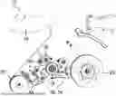
FIG. 1 shows a schematic front view of an application device 10 according to the invention during the execution of the method according to the invention.
The application device 10 according to the invention comprises a first reel receptacle 14, which is embodied as a mandrel, on which an adhesive tape reel 16 is arranged in a reversible and nondestructively exchangeable manner, such that the said reel is rotatable. The adhesive tape reel 16 comprises a web-shaped adhesive element 12, on the outer side of which in the radial direction a release liner is arranged as a web-shaped release material 32. The joint material web of the web-shaped adhesive element 12 and the web-shaped release material 32 is guided through a roller nip 40, which is formed between a pre-feed roller 18 and a spring-mounted counter roller 38 arranged opposite.
Arranged downstream of the roller nip 40 in the web direction is a parting device 44, which is embodied as a cutting device in the example shown, wherein the cutting edge is about 20% wider than the width of the web-shaped adhesive element 12 transversely to the web direction. Downstream of the parting device 44 in the web direction, the material web is guided over a knife edge, at which the web-shaped release material 32 is deflected by more than 90° and is pulled off the web-shaped adhesive element 12. After being removed, the web-shaped release material 32 is guided to a take-up reel 28 and wound up there.
The take-up reel 28 is mounted rotatably on a second reel receptacle 30, which is likewise embodied as a mandrel. As soon as the take-up reel 28 is completely filled with wound-up web-shaped release material 32, it can be removed from the application device 10 and exchanged for an empty take-up reel 28. Downstream of the knife edge in the application device 10, the web-shaped adhesive element 12 freed from the web-shaped release material 32 is guided to the application roller 20, via which the web-shaped adhesive element 12 is then rolled onto a substrate 48.
In the embodiment shown in FIG. 1, the pre-feed roller 18, the counter roller 38, the first reel receptacle 14 and the second reel receptacle 30 are each coupled to one another kinematically in such a way that rotation of the application roller 20 is in each case converted into rotation of the other rotatable elements. The web-shaped adhesive element 12 is thereby conveyed gently through the application device 10 to the application roller 20, while the web-shaped release material 32 is simultaneously wound up.
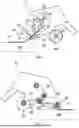
FIG. 2 shows a schematic illustration of the rear side of the application device 10 from FIG. 1. The counter discs of the application roller 20, of the pre-feed roller 18, of the first reel receptacle 14, of the second reel receptacle 30 and of the counter roller 38, which are firmly connected to the respective rotation axis, are each shown with hatching. In the example in FIG. 2, the first coupling mechanism 26 and the second coupling mechanism 34 are configured as a common overall coupling mechanism, whereas the third coupling mechanism 36 and the fourth coupling mechanism 42 are likewise embodied as a separate overall coupling mechanism. In the example shown, all the coupling mechanisms are implemented exclusively by non-positive belt transmissions, wherein the use of crossed belt routing in the first coupling mechanism 26 has the effect that the pre-feed roller 18 and the take-up reel 28 have an inverted direction of rotation relative to the application roller 20.
FIG. 3 shows a schematic illustration of a rotatable application roller 20 during the application of a web-shaped adhesive element 12 to a substrate 48. The front view of this construction is shown in FIG. 4. FIG. 4 illustrates that the applied web-shaped adhesive element 12 is guided in the encircling depression 24 of the application roller 20. Respective encircling friction elements 46a, 46b, which are embodied as rubber rings, are arranged on both sides of the encircling depression 24. The encircling friction elements 46a, 46b form the edge of the encircling depression 24, which also extends into the lateral surface 22. During the application of the web-shaped adhesive element 12 to a substrate 48, the friction elements 46a, 46b make contact with its surface and prevent the web-shaped adhesive element 12 guided in the encircling depression 24 from being excessively compressed.
FIGS. 5 and 6 show an application device 10 according to the invention in a particularly preferred configuration. In this particularly preferred configuration, the application roller 20 is coupled to the pre-feed roller 18 and the take-up reel 28, which is of non-exchangeable design, wherein the first coupling mechanism 26 and the second coupling mechanism 34 are embodied as an overall coupling mechanism. For the overall coupling mechanism, reliance is here placed in the first instance on a positive coupling with the application roller 20 in the form of a gearwheel transmission, by means of which the direction of rotation is inverted. After transfer, the rotation is transmitted by a toothed belt to an intermediate roller, which is positioned in the rear part of the application device 10 and is, in turn, coupled on the front side of the application device, via corresponding toothed belts, to the pre-feed roller 18 and the take-up reel 28. In the illustrative application device 10 in FIGS. 5 and 6, the spring-mounted counter roller 38 is driven as little as the adhesive tape reel 16.
Using application devices according to the invention as shown in FIGS. 1 and 2 or FIGS. 5 and 6, it is possible to apply even particularly pressure-and strain-sensitive adhesive tapes, especially those with foamed adhesive compounds and passivated surfaces, reliably and reproducibly with a high quality. During application, the configuration of the application roller 20 allows advantageously small curve radii and, by virtue of the encircling friction elements 46a, 46b embodied as rubber rings, allows reliable and slip-resistant contacting of the substrate 48 to be bonded.
LIST OF REFERENCE SIGNS
-
- 10 application device
- 12 web-shaped adhesive element
- 14 first reel receptacle
- 16 adhesive tape reel
- 18 pre-feed roller
- 20 application roller
- 22 lateral surface
- 24 encircling depression
- 26 first coupling mechanism
- 28 take-up reel
- 30 second reel receptacle
- 32 web-shaped release element
- 34 second coupling mechanism
- 36 third coupling mechanism
- 38 counter roller
- 40 roller nip
- 42 fourth coupling mechanism
- 44 parting device
- 46a-b encircling friction element
- 48 substrate
Claims
1. An application device for the application of web-shaped adhesive elements, the application device comprising:
i) a first reel receptacle, wherein the first reel receptacle configured such that an adhesive tape reel filled with a web-shaped adhesive element can be arranged rotatably in the first reel receptacle,
ii) a rotatable pre-feed roller, and
iii) a rotatable application roller, wherein a lateral surface of the application roller has a depression running along the circumferential direction,
wherein the application device is configured such that a web-shaped adhesive element provided by an adhesive tape reel arranged in the first reel receptacle can be guided via the pre-feed roller to the application roller,
wherein the application roller and the pre-feed roller are coupled by a first coupling mechanism, such that rotation of the application roller brings about rotation of the pre-feed roller.
2. The application device of claim 1, wherein the application device is a manual applicator.
3. The application device of claim 1, further comprising:
iv. a) a rotatable take-up reel, or
iv. b) a second reel receptacle, wherein the second reel receptacle is configured such that a take-up reel can be arranged rotatably in the second reel receptacle,
wherein the application device is configured to enable a web-shaped release material separated from a web-shaped adhesive element guided in the application device to be wound up on the take-up reel.
4. The application device of claim 3, wherein the application roller and the take-up reel are coupled by a second coupling mechanism, such that rotation of the application roller brings about rotation of the take-up reel.
5. The application device of claim 1, wherein the application roller and the first reel receptacle are coupled by a third coupling mechanism, such that rotation of the application roller brings about rotation of an adhesive tape reel arranged in the first reel receptacle.
6. The application device of claim 1, further comprising:
v) a rotatable counter roller,
wherein the counter roller, together with the pre-feed roller, forms a roller nip arranged between the counter roller and the pre-feed roller, wherein the application device is configured to enable the web-shaped adhesive element guided in the application device to be passed through the roller nip to the application roller.
7. The application device of claim 6, wherein the counter roller is spring-mounted, such that the roller nip can be widened against the spring force of the spring mounting, and/or such that the counter roller exerts a predetermined contact pressure against the pre-feed roller on the web-shaped adhesive element guided in the roller nip.
8. The application device of claim 1, wherein the application roller and the counter roller are coupled by a fourth coupling mechanism, such that rotation of the application roller brings about rotation of the counter roller.
9. The application device of claim 1, further comprising:
vi) a parting device, wherein the parting device is configured to part the web-shaped adhesive element guided in the application device upstream of the application roller in relation to the web path in the application device.
10. The application device of claim 1, wherein the first coupling mechanism, the second coupling mechanism, the third coupling mechanism, and/or the fourth coupling mechanism are based on positive coupling.
11. The application device of claim 10, wherein the first coupling mechanism, the second coupling mechanism, the third coupling mechanism, and/or the fourth coupling mechanism are based on a wheel mechanism.
12. The application device of claim 1, wherein the application roller and the pre-feed roller are coupled such that rotation of the application roller brings about rotation of the pre-feed roller in the opposite direction of rotation.
13. The application device of claim 1, wherein the application roller and the take-up reel are coupled such that rotation of the application roller brings about rotation of the take-up reel in the opposite direction of rotation.
14. The application device of claim 1, wherein the application roller comprises an encircling friction element above and/or below the encircling depression along the axial direction.
15. A method for applying web-shaped adhesive elements by means of the an application device of claim 1, the method comprising:
a) providing the adhesive tape reel, filled with a wound-up web-shaped adhesive element, in the first reel receptacle of the application device,
b) arranging a free end portion of the web-shaped adhesive element in the application device, such that the web-shaped adhesive element runs between the application roller and the adhesive tape reel in such that, in relation to the web path in the application device, the web-shaped adhesive element is guided between the application roller and the adhesive tape reel via the pre-feed roller, and
c) applying the web-shaped adhesive element to a substrate to be bonded,
wherein, during application, the web-shaped adhesive element is guided through the encircling depression of the application roller,
wherein, during application, the application roller is rolled over the substrate to be bonded,
wherein the rotation of the application roller by the first coupling mechanism brings about rotation of the pre-feed roller, and
wherein, in relation to the web path in the application device, the rotation of the pre-feed roller brought about by the first coupling mechanism conveys the web-shaped adhesive element in the direction of the application roller.
Images & Drawings included:


Sources:
- United States Patent and Trademark Office - verify current appl. status at the USPTO↗
Recent applications in this class:
- » 20250368466 2025-12-04
HANDHELD TAPE DISPENSER AND METHODS OF USE THEREOF - » 20250326599 2025-10-23
DUAL ROLLER APPLICATOR FOR SEAM TAPE - » 20250206558 2025-06-26
TAPE APPLICATOR - » 20250197154 2025-06-19
HEAD FOR TAPING DEVICE - » 20250115451 2025-04-10
TAPE CUTTER - » 20250019198 2025-01-16
TAPE CUTTER - » 20240208763 2024-06-27
Surface Characterization Module and System Including Same - » 20240199365 2024-06-20
TAPE APPLICATOR AND METHOD OF USING - » 20240132320 2024-04-25
TAPE APPLICATOR APPARATUS - » 20240124258 2024-04-18
TAPE AFFIXING SYSTEM
Recent applications for this Assignee:
- » 20260103625 2026-04-16
ADHESIVE COMPOUND, ADHESIVE TAPE, BONDED COMPOSITE, AND METHOD FOR ELECTRICALLY DEBONDING THE BONDED COMPOSITE - » 20260097916 2026-04-09
APPLICATION DEVICE HAVING REFILLING CASSETTE - » 20260078283 2026-03-19
ADHESIVE TAPE WITH AN ELECTRICALLY RELEASABLE ADHESIVE LAYER, ASSEMBLY, METHOD AND USE - » 20260062246 2026-03-05
COMPACT END EFFECTOR FOR THE APPLICATION OF DOUBLE-SIDED ADHESIVE TAPES WITH AN INTEGRATED ROLL - » 20260048954 2026-02-19
CASSETTE UNIT FOR USE IN APPLICATION SYSTEMS FOR THE APPLICATION OF ADHESIVE ELEMENTS - » 20250206991 2025-06-26
ADHESIVE TAPE FOR JACKETING ELONGATE ITEMS SUCH AS ESPECIALLY CABLE HARNESSES AND METHOD FOR JACKETING - » 20250206990 2025-06-26
ADHESIVE TAPE FOR JACKETING ELONGATE ITEMS SUCH AS ESPECIALLY CABLE HARNESSES AND METHOD FOR JACKETING - » 20250092287 2025-03-20
WEB-SHAPED ADHESIVE COMPOUND CONTAINING A POLYURETHANE- AND/OR SILICONE-BASED FILLER - » 20250083410 2025-03-13
PUNCHED ARTICLE, IN PARTICULAR FOR PERMANENTLY CLOSING HOLES - » 20250075112 2025-03-06
OPTICAL TRANSPARENT ADHESIVE LAYER WITH BOTH BUBBLE RESISTANCE AND YELLOWING RESISTANCE AND ITS APPLICATION