DISPENSING SYSTEM AND ASSEMBLY FOR CABLE SPOOLS AND SAID CABLE SPOOLS
US20260109568A1
2026-04-23
19/121,617
2023-09-08
Smart Summary: A system is designed to help dispense cables from spools easily. It has a base that supports the spool while the cable is being pulled out. The base has two parts: a fixed part that stays still on the surface and a rotating part that turns with the spool. The spool can be easily attached and removed from the rotating part. Special surfaces on both the rotating part and the spool help keep the spool securely in place while it spins. 🚀 TL;DR
Abstract:
A dispensing system for cable spools comprising a support base for supporting a spool as the cable is dispensed. The support base substantially extends over a plane perpendicular to the axis of the spool, that is, the imaginary axis of the cylinder of the spool that longitudinally passes through the hollow of the spool. The support base comprises a fixed part that rests on the work surface, and a rotary part rotating according to the axis of the hollow of the spool with respect to the fixed part. The spool is detachably secured to the rotary part. The dispensing system comprises opposing distributed coupling surfaces, which are respectively arranged on the rotary part and on a base of the spool to secure the spool to the rotary part.
Applicant:
Interested in similar patents?
Get notified when new applications in this technology area are published.
Classification:
B65H49/28 » CPC main
Unwinding or paying-out filamentary material; Supporting, storing or transporting packages from which filamentary material is to be withdrawn or paid-out; Methods or apparatus in which packages rotate; Package-supporting devices Turntables, i.e. package resting on a table
Description
TECHNICAL FIELD
The present invention relates to the industrial sector of the spooling of cables, wires and the like, referring more specifically to a dispensing system or dispenser for cable spools, or any other type of materials such as wires, ropes, optical fibre, etc., which is portable to be handled directly by operators or by means of machinery.
Likewise, the description of the invention is mainly oriented to spools that can be handled without machinery, their application or use being non-limiting.
STATE OF THE ART
Both in industry and in the market in general, it is common for elements such as long and very long cables to be wound on themselves in cylinders to form spools. This arrangement makes it more economical from the point of view of manufacturing, ease of handling, transport and storage, among others.
In order to remove the cable from the spool, a pulling force must be exerted which, in an ideal situation, should only cause the spool to rotate. In practice, however, this pulling force can also cause the spool to move longitudinally across the working space, resulting not only in the inconvenience of constantly repositioning said spool, but also in a possible tripping hazard for other users of the site.
In order to solve this problem, cable dispensing systems are known in the state of the art in which a body comprising a base and a transverse central shaft receives the spool by passing said central shaft through the hollow of the spool, which allows the spool to rotate during cable dispensing.
Specifically, WO2015043604A1 discloses a dispensing system comprising a base with a fixed part and a rotary part on which the spool sits, a central protrusion passing through the central hollow of which, the base having a second, smaller protrusion at a point on the perimeter of the fixed part for guiding the cable during dispensing.
This solution has the drawback that accidental removal of the spool may occur due to a possible clearance between the central protrusion and the hollow of the spool and the fact that the spool is not secured to the fixed part of the dispensing system.
Furthermore, the above mentioned solution is not useful for all spool sizes, as the central protrusion has a fixed diameter which does not have to match the hollow of all spools, especially the smaller ones. This problem would mean having to purchase multiple dispensers for the different sizes of spools.
Another problem is that this system must be assembled and disassembled for transport, with a large number of parts, which makes it cumbersome to use and has a negative effect on the time required to carry out the tasks.
OBJECT OF THE INVENTION
To overcome the above mentioned drawbacks, the present invention proposes a dispensing system for cable spools comprising a support base for supporting a spool as the cable is dispensed. The support base substantially extends over a plane perpendicular to the axis of the spool, that is, the imaginary axis of the cylinder of the spool that longitudinally passes through the hollow of the spool. The support base comprises a fixed part that rests on the work surface, and a rotary part rotating according to the axis of the hollow of the spool with respect to the fixed part. The spool is detachably secured to the rotary part.
According to the invention, the dispensing system comprises opposing distributed coupling surfaces, which are arranged respectively on the rotary part and on a base of the spool, hereinafter referred to as a securing base, for securing the spool to the rotary part.
In the context of the invention, the term “opposing distributed coupling surfaces” is understood as surfaces provided with distributed couplings with an opposite configuration, such that they engage each other when positioned opposite each other. Examples of opposing distributed coupling surfaces are those consisting of hook-loop, hook-and-loop, hollow-socket, etc. or the so-called Velcro®.
In order to use it, the user connects the securing base of the spool, which has a distributed coupling surface, to the opposing distributed coupling surface arranged on the rotary part of the support base. Then said support base is placed with the spool, hereinafter referred to as the dispensing assembly, on the work surface and the cable is pulled, causing the spool to rotate without unwanted movement or accidental disassembly. The connection by means of opposing distributed coupling surfaces enables simple assembly/disassembly, regardless of the spool size.
The opposing distributed coupling surfaces provide a detachable securing system the opposing and even surfaces of which are fixed by direct contact, but without causing permanent adhesion and can be reused an indefinite number of times. In this way, the dispensing system of the invention provides the advantage of being easily assembled and disassembled without the use of tools, as well as being more conveniently transported, reducing assembly and disassembly times.
The dispensing system according to the invention preferably features a plurality of distributed coupling surfaces which are arranged on the rotary part and/or a plurality of distributed coupling surfaces which are arranged on the securing base of the spool, said surfaces being arranged with angular symmetry with respect to the axis of the spool.
By angular symmetry of the arrangement of the distributed coupling surfaces in the context of the invention, it is to be understood that said surfaces are arranged in a pattern of angularly equidistant elements with respect to the axis of the spool.
This configuration of the angularly symmetrical arrangement makes it easier to assemble the spool in the position where it is secured to the rotary part, as it allows it to be positioned regardless of the orientation of the spool with respect to its axis.
Also preferably, at least one of the two opposing distributed coupling surfaces extends annularly around the axis of the spool.
In this context, distributed coupling surfaces extending annularly are understood as those surfaces that are crown-shaped or ring-shaped and arranged concentrically around the axis of the spool on the surface of the rotary part and/or the securing base of the spool. This arrangement has the advantage of making it easier to assemble the spool on the rotary part regardless of the orientation of the spool, thus reducing assembly time.
This support base may be substantially circular or polygonal (square, triangular, etc.) in shape from a plan perspective view.
Additionally, said support base may have a central through hole to reduce the weight of the support base and facilitate its transport.
Preferably, the opposing distributed coupling surfaces are arranged substantially flat on the respective rotary part and securing base of the spool, so that the faces of the rotary part and the spool securing base are flat. This facilitates the securing and stability of the assembly formed by the spool and the rotary part.
Moreover, the opposing distributed coupling surfaces are preferably in sheet form, the dispensing system comprising at least one rotary part securing sheet, connected to the rotary part, and at least one securing base securing sheet, connected to the base of the spool, said sheets being provided with the respective opposing distributed coupling surfaces.
Additionally, the support base may comprise a guiding flange to guide the positioning of the spool to the securing position on said support base. This design is advantageous as it further facilitates the positioning of the spool to the securing position.
An advantage of this dispensing system is that a multitude of dispensing system designs can be manufactured to suit all industry requirements, as long as they fulfil the function for which they are designed.
Advantageously, the support base according to the invention does not require a central bar or protrusion to be inserted into the hollow of the spool as in known dispensing systems, allowing multiple spool sizes to be secured, with the consequent savings in materials. Furthermore, compared to said known dispensing systems, the use of opposing distributed coupling surfaces reinforces the securing of the dispensing assembly by preventing accidental separation of the spool from the support base due to possible clearances between the spool and the central bar or protrusion.
A further advantage of this dispensing system is the easy transport of the dispensing assembly, as the securing between the opposing distributed coupling surfaces prevents accidental separation of the two parts.
Another advantageous option is the easy disassembly of the assembly, as the user only has to detach the spool from the rotary part by exerting a pulling force perpendicular to the plane of the support base, resulting in the separation of the opposing distributed coupling surfaces and thus of the dispensing assembly.
In accordance with another aspect of the invention, the invention also relates to a dispensing assembly comprising a cable spool and a dispensing system for said spool, which spools being secured to the rotary part by means of the opposing distributed coupling surfaces.
Preferably, the securing base of the spool with said distributed coupling surface also includes a positioning mark that facilitates the positioning of the spool with respect to the rotary part of the support base, improving the securing of the assembly as well as assembly times.
Likewise, and in accordance with another aspect of the invention, the invention also relates to a cable spool to be secured with the dispensing system subject of the invention the securing base of which comprises a distributed coupling surface for securing the spool to a distributed coupling surface opposite to said distributed coupling surface.
Additionally and preferably, the spool comprises a handle for transporting the spool or dispensing assembly, thus facilitating the transport of the spool or dispensing assembly by the user. Preferably, said handle is installed centred with respect to the base of the spool opposite to the securing base of said spool, for example, on said base of the opposite spool or in the hollow of the spool. The handle can be fixed or detachably anchored.
DESCRIPTION OF THE FIGURES
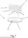
FIG. 1 is a perspective view of an embodiment according to the invention of the unassembled dispensing assembly with a substantially circular support base.
FIG. 2 is a perspective view of another embodiment according to the invention of the unassembled dispensing assembly with a substantially square support base.
FIG. 3 shows a perspective view of the same embodiment as above, but without cable.
FIG. 4 is a perspective view of an exemplary embodiment of a cable spool incorporating a handle and applicable to the invention.
FIG. 5 is the same embodiment as above without cable.
FIG. 6 shows a perspective view of an embodiment of the support base with a flange.
FIGS. 7A and 7B show perspective views of embodiments in accordance with the invention, with different arrangements and shapes of distributed coupling surfaces for an embodiment in which the support base is substantially square.
FIGS. 8A and 8B show perspective views of embodiments in accordance with the invention, with different arrangements and shapes of distributed coupling surfaces for an embodiment in which the support base is substantially circular.
FIG. 9 is a detail view of oppositely arranged distributed coupling surfaces in accordance with the invention.
DETAILED DESCRIPTION OF THE INVENTION
The invention now advocated relates to a spool cable dispensing system comprising opposing distributed coupling surfaces (4, 5) that are easily detachable and reusable, which allow the spool (6) to be firmly secured to a support base (1), while said support base (1) provides the dispensing assembly with freedom to rotate for easy dispensing of the cable (10) by the user. On the one hand, the support base (1) comprises a fixed part (2) and a rotary part (3) the shape of which is substantially circular or polygonal.
Likewise, said support base (1) may have a central hollow (11), regardless of its shape, to reduce its weight and thus facilitate the transport of the dispensing assembly. An example of a support base (1) with said hollow (11) can be seen in FIGS. 2,3, 7A and 7B.
On the other hand, said opposing distributed coupling surfaces (4, 5) are arranged respectively on the rotary part (3) and a base (7) of the spool (6) for securing the spool (6) to the rotary part (3). An example of distributed coupling surfaces can be seen in FIGS. 1 to 3, 7A to 8B and 9.
Both opposing distributed coupling surfaces (4, 5) comprise an attachment face (4.1, 5.1) which is attached respectively to the surface of the rotary part (3) and to a base (7) of the spool (6), and a securing face with distributed couplings (4.2, 5.2) as shown in FIG. 9, which furthermore provides an example of opposing distributed coupling surfaces (4, 5) in the form of a rotary part securing sheet (40) on the one hand and a securing base securing sheet (50) on the other hand, this design not being limiting.
In order to dispense the cable manually, according to one embodiment of the invention, a user carries the dispensing assembly, i.e. the spool (6) secured to the rotary part (3) of the support base (1) and places it on the work surface to proceed with the removal of the cable (10) without risk of the spool (6) sliding on the work surface and, once the task is completed, the excess cable (10) must be simply wound up and the dispensing assembly transported again, or, in the event of having to carry out a different wiring, the spool (6) must be simply detached from the support base (1) and another spool (6) with a different cable (10) be positioned.
In a preferred configuration shown in FIGS. 2, 7A and 7B, the support base (1) has a substantially square design with a central hollow (11) the sides of which coincide with the positioning marks (9).
This dispensing system of FIGS. 2, 7A and 7B features a plurality of opposing distributed coupling surfaces (4, 5) which are arranged with angular symmetry with respect to the axis of the spool (6), that is, the imaginary axis of the cylinder of the spool that longitudinally passes through the hollow of the spool (8).
In another preferred configuration as depicted in FIGS. 1, 8A and 8B the cable dispensing system comprises a substantially circular support base (1) on which a rotary part distributed coupling surface (4) is attached, while the spool distributed coupling surface (5) is attached on a base (7) of the spool (6), which also includes a positioning mark (9) to facilitate the positioning between the spool (6) and the support base (1).
Another preferred configuration presented in FIGS. 4 and 5 shows a spool (6) with and without cable (10) respectively, with a handle (13) arranged centred with respect to the base of the spool (6) opposite to the base (7) for securing said spool (6), thus facilitating the transport and handling of the spool (6) by the user.
In addition to the above mentioned configurations for the support base (3), a support base design (1) with a guiding flange (12) on its periphery, as shown in FIG. 6, is provided to facilitate alignment and improve the stability of the spool (6) when dispensing the cable (10). Similarly, the support base (1) may have a protrusion, not shown, on the outer edge to prevent the cable (10) from falling to the ground during dispensing.
In the same vein, it is worth mentioning that the design of different configurations of support bases (1) and of opposing distributed coupling surfaces (4, 5) is contemplated. Specifically, FIGS. 7A, 7B and 8A, 8B show opposing distributed coupling surfaces (4, 5) with annular or individual designs, although other configurations are allowed, always respecting the essence of the invention.
The design and manufacture of different sizes of spools (6) and support bases (1), as well as of opposing distributed coupling surfaces (4, 5), is contemplated in order to cover all the industry requirements, respecting the essence of the invention at all times.
Although FIG. 9 shows opposing hook-loop type distributed coupling surfaces (4, 5), the use of other similar types that maintain the essence of the invention is contemplated.
Finally, it is contemplated that the spool will have base securing surfaces (5) and positioning marks (9) on both bases due to its symmetrical design.
Claims
1. A dispensing system for cable spools, comprising a support base (1) for supporting a spool (6) as the cable is dispensed, extending substantially in a plane perpendicular to the axis of the spool and having a fixed part (2), and a rotary part (3) according to an the axis of the spool (6) with respect to the fixed part (2), the spool (6) being detachably secured to the rotary part (3), opposingly distributed coupling surfaces (4, 5) arranged respectively on the rotary part (3) and a base (7) of the spool (6) for attaching the spool (6) to the rotary part (3).
2. The dispensing system, according to claim 1, further comprising a plurality of distributed coupling surfaces (4) which are arranged on the rotary part (3) and/or distributed coupling surfaces (5) which are arranged on the base (7) for securing the spool (6), said opposingly distributed coupling surfaces (4, 5) being arranged with angular symmetry with respect to the axis of the spool (6).
3. The dispensing system according to claim 1, wherein at least one of the two opposingly distributed coupling surfaces (4, 5) extends annularly around the axis of the spool (6).
4. The dispensing system, according to claim 1, wherein the support base (1) has a substantially circular or polygonal shape.
5. The dispensing system, according to claim 1, wherein the support base (1) has a central through hole (11).
6. The dispensing system, according to claim 1, wherein the opposingly distributed coupling surfaces (4,5) are arranged substantially flat on the respective rotary part (3) and base (7) for securing the spool.
7. The dispensing system according to claim 1, further comprising a rotary part securing sheet (40) which is attached to the rotary part (3) and a securing base securing sheet (50) which is connected to the securing base (7) of the spool (6), said rotary part securing sheet and said securing base securing sheet being provided with respective opposingly distributed coupling surfaces (4, 5).
8. The dispensing system, according to claim 1, wherein the support base (1) comprises a guiding flange (12) to guide the positioning of the spool (6) to a securing position.
9. A dispensing assembly for cable spools, comprising a cable spool (6) and a dispensing system for said spool (6) according to claim 1.
10. The dispensing assembly according to claim 9, wherein the base (7) for securing the spool (6) and/or the rotary part (3) of the support base (1) has a positioning mark (9) to mark the securing position of the spool (6) with respect to the rotary part (3) of the support base (1).
11. A cable spool for a dispensing assembly according to claim 9, further comprising a distributed coupling surface (5) arranged on the base (7) for securing the spool (6) to secure the spool (6) to a distributed coupling surface opposite to said distributed coupling surface (5).
12. The cable spool, according to claim 11, further comprising a handle (13) for transporting the spool (6) or the dispensing assembly.
13. The cable spool according to claim 11, wherein the handle (13) is centered with respect to the base of the spool (6) opposite to the base (7) for securing said spool (6).
Images & Drawings included:


Sources:
- United States Patent and Trademark Office - verify current appl. status at the USPTO↗
Recent applications in this class:
- » 20240391729 2024-11-28
DISPENSER FOR TELECOMMUNICATIONS CABLES - » 20240017958 2024-01-18
ERGONOMIC ADJUSTABLE INNER DIAMETER TURNTABLE FOR SIMPLIFYING CABLE PAYOFF - » 20230399193 2023-12-14
CABLE CAROUSEL FOR HEAVY-DUTY ELECTRIC CABLE OR UMBILICAL - » 20220144578 2022-05-12
SINGLE-USE CABLE PAYOFF SYSTEMS WITH REDUCED PULL RESISTANCE - » 20210147173 2021-05-20
Apparatus for storing cable - » 20190389685 2019-12-26
Modular sections for temporary turntable applications - » 20190382230 2019-12-19
FLAT CABLE WINDING DEVICE - » 20190322479 2019-10-24
System and a method for handling, storing and transportation - » 20180290856 2018-10-11
Pipe Unroller - » 20170121146 2017-05-04
Modular sections for temporary turntable applications