EXCAVATOR AND CONTROL DEVICE
US20260110153A1
2026-04-23
19/362,629
2025-10-20
Smart Summary: An excavator is designed to make construction work more efficient. It has a moving base and a rotating upper part that holds an arm and a bucket. The bucket can tilt and pivot to reach the right angle for digging. A special control device allows the bucket to tilt and pivot at the same time. This helps keep the bucket level with the surface being excavated, making the digging process easier and more accurate. 🚀 TL;DR
Abstract:
To improve construction work efficiency, an excavator includes: a self-propelled lower traveling body; an upper rotating body rotatably provided on the lower traveling body; an arm pivotally attached to a boom pivotally attached to the upper rotating body; a bucket pivotally attached to the arm; a tilt mechanism configured to tilt the bucket with respect to the arm; a pivoting mechanism configured to pivot the bucket with respect to the arm; and a control device including a processor and a memory, and configured to make tilting of the bucket by the tilt mechanism and pivoting of the bucket by the pivoting mechanism simultaneously operable in order to make a target line passing through a predetermined position of the bucket parallel with an excavation target surface.
Applicant:
Interested in similar patents?
Get notified when new applications in this technology area are published.
Classification:
E02F3/437 » CPC main
Dredgers; Soil-shifting machines mechanically-driven with digging tools mounted on a dipper- or bucket-arm, i.e. there is either one arm or a pair of arms , e.g. dippers, buckets; Component parts; Drives for dippers, buckets, dipper-arms or bucket-arms; Control of dipper or bucket position; Control of sequence of drive operations for dipper-arms, backhoes or the like providing automatic sequences of movements, e.g. linear excavation, keeping dipper angle constant
E02F3/43 IPC
Dredgers; Soil-shifting machines mechanically-driven with digging tools mounted on a dipper- or bucket-arm, i.e. there is either one arm or a pair of arms , e.g. dippers, buckets; Component parts; Drives for dippers, buckets, dipper-arms or bucket-arms Control of dipper or bucket position; Control of sequence of drive operations
Description
CROSS-REFERENCE TO RELATED APPLICATION
The present application claims priority under 35 U.S.C. § 119 to Japanese Patent Application No. 2024-186861, filed Oct. 23, 2024, the contents of which are incorporated herein by reference in their entireties.
BACKGROUND OF THE INVENTION
Field of the Invention
The present disclosure relates to an excavator and a control device.
Description of the Related Art
Recently, excavators equipped with a tilt rotator mechanism have been known.
SUMMARY OF THE INVENTION
Even such excavators as described above are desired to have an improved construction work efficiency.
An excavator of the present disclosure includes: a self-propelled lower traveling body; an upper rotating body rotatably provided on the lower traveling body; an arm pivotally attached to a boom pivotally attached to the upper rotating body; a bucket pivotally attached to the arm; a tilt mechanism configured to tilt the bucket with respect to the arm; a pivoting mechanism configured to pivot the bucket with respect to the arm; and a control device including a processor and a memory, and configured to make tilting of the bucket by the tilt mechanism and pivoting of the bucket by the pivoting mechanism simultaneously operable in order to make a bucket line of the bucket parallel with an excavation target surface.
In an excavator including: an arm pivotally attached to a boom pivotally attached to a rotating body; a bucket pivotally attached to the arm; and a control device including a processor and a memory and configured to control operations of the boom, the arm, and the bucket, the control device has: a first mode for keeping an angle formed between the arm and the bucket constant; a second mode for keeping an angle formed between an excavation target surface and a bottom surface of the bucket constant; and a third mode for making a target line passing through a predetermined position of the bucket parallel with the excavation target surface.
A control device of the present disclosure is a control device of an excavator including: an arm pivotally attached to a boom pivotally attached to a rotating body; a bucket pivotally attached to the arm; a tilt mechanism configured to tilt the bucket with respect to the arm; and a pivoting mechanism configured to pivot the bucket with respect to the arm, wherein the control device includes a processor and a memory, and is configured to make tilting of the bucket by the tilt mechanism and pivoting of the bucket by the pivoting mechanism simultaneously operable.
According to the present disclosure, the construction work efficiency can be improved.
BRIEF DESCRIPTION OF THE DRAWINGS
FIG. 1 is a side view of an excavator according to an embodiment of the present disclosure;
FIG. 2 is a block diagram showing a configuration of a drive system of the excavator shown in FIG. 1;
FIG. 3 is a block diagram showing a functional configuration of a controller;
FIG. 4 is a diagram illustrating an operation of a bucket;
FIG. 5 is a flowchart illustrating a process for enabling/disabling control on a bucket;
FIG. 6 is a flowchart illustrating a process for pivoting a bucket to make a bucket line along a claw of the bucket parallel with an excavation target surface;
FIG. 7 is a view showing an example of a situation in which it is impossible to make a bucket line along a claw of the bucket parallel with an excavation target surface even by tilting the bucket 6;
FIG. 8 is a view showing an example of a situation in which the bucket 6 is pivoted to make a bucket line along a claw of the bucket parallel with an excavation target surface;
FIG. 9 is a flowchart illustrating a process for disabling previously enabled control on the bucket 6; and
FIG. 10 is a view showing an example of a system in which an excavator is remotely operated.
DETAILED DESCRIPTION OF THE DISCLOSURE
Embodiments of the present disclosure will be described below with reference to the drawings.
[Shovel Configuration]
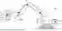
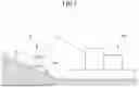
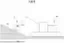
FIG. 1 is a side view of an excavator according to an embodiment.
As shown in FIG. 1, an upper rotating body 3 is mounted on a lower traveling body 1 of an excavator 200 via a rotating mechanism 2. A boom 4 is pivotally attached to the upper rotating body 3. The lower traveling body 1 is a self-propelled type. An arm 5 is pivotally attached to the tip of the boom 4, and a bucket 6 serving as an end attachment is pivotally attached to the tip of the arm 5. A slope bucket, a dredging bucket, and the like may be used as the end attachment.
The boom 4, the arm 5, and the bucket 6 constitute an excavation attachment as an example of an attachment, and are hydraulically driven by a boom cylinder 7, an arm cylinder 8, and a bucket cylinder 9, respectively. A boom angle sensor S1 is attached to the boom 4, an arm angle sensor S2 is attached to the arm 5, and a bucket angle sensor S3 is attached to the bucket 6. The boom angle sensor S1, the arm angle sensor S2, and the bucket angle sensor S3 may be referred to as “attitude sensors”. The bucket cylinder 9 is an example of a pivoting mechanism according to the present disclosure.
The excavator 200 includes a tilt rotator 20 between the arm 5 and the bucket 6. The tilt rotator 20 can change the angle of the bucket 6 in the left-right direction (the width direction or the yaw direction: hereinafter referred to as tilt angle) with respect to the center of the arm 5, and can change the angle of the bucket 6 about a shaft of a base end of the bucket 6 (in the roll direction: hereinafter referred to as roll angle).
Therefore, the tilt rotator 20 includes a tilt mechanism 23 provided on the arm 5 side, and a rotator mechanism 22 provided between the tilt mechanism 23 and the bucket 6. The tilt mechanism 23 includes a base 211 fixed to the arm 5, a tilt shaft 212 connected to the base 211, a support plate 213 swingably supported on the tilt shaft 212, and a tilt actuator 214 for changing the tilt angle of the support plate 213. The tilt actuator 214 is composed of, for example, a pair of cylinder mechanisms between which the tilt shaft 212 is sandwiched.
The rotator mechanism 22 includes a rotation motor 221 fixed to the support plate 213 of the tilt mechanism 23, a rotation shaft 222 rotated by the rotation motor 221, and a connection part 223 connecting the rotation shaft 222 and the bucket 6. The rotation shaft 222 projects by a short length from the center of the support plate 213 and is connected to the connection part 223. The connection part 223 fixes the center of the base end of the bucket 6, and adjusts the roll angle of the bucket 6 by rotating the bucket 6 about the center axis of the base end of the bucket 6.
The excavator 200 changes the bucket angle (pitch angle) of the entirety of the tilt rotator 20 and the bucket 6 integrally by rotating the entirety of the tilt rotator 20 in the pitch direction in accordance with an extension or contraction operation of the arm cylinder 8. The excavator 200 also changes the tilt angle (yaw angle) of the bucket 6 by rotating the support plate 213 in the left-right direction with respect to the base 211 in accordance with the operation of the tilt actuator 214. For example, the tilt angle of the bucket 6 is adjusted within a range of 45° to the right and 45° to the left. Further, the excavator 200 changes the roll angle of the bucket 6 by rotating the connection part 223 and the bucket 6 about the axis in accordance with the operation of the rotate motor 221. For example, the roll angle of the bucket 6 is adjusted within a range of 360° with respect to the support plate 213.
The tilt mechanism 23 includes a bucket tilt angle sensor S5. The bucket tilt angle sensor S5 is a sensor that detects a rotation angle (tilt angle) of the bucket 6 about the tilt shaft 212 and outputs the detected value. The rotator mechanism 22 includes a rotation angle sensor S6. The rotation angle sensor S6 is a sensor that detects an angle (roll angle) of the bucket 6 about the axis of the base end of the bucket 6 and outputs the detected value.
The boom angle sensor S1 detects the rotation angle of the boom 4. In the present embodiment, the boom angle sensor S1 is an acceleration sensor that detects an inclination with respect to a horizontal plane and detects a pivoting angle of the boom 4 with respect to the upper rotating body 3. The arm angle sensor S2 detects a pivoting angle of the arm 5. In the present embodiment, the arm angle sensor S2 is an acceleration sensor that detects an inclination with respect to a horizontal plane and detects a pivoting angle of the arm 5 with respect to the boom 4. The bucket angle sensor S3 detects a pivoting angle of the bucket 6. In the present embodiment, the bucket angle sensor S3 is an acceleration sensor that detects an inclination with respect to a horizontal plane and detects a pivoting angle of the bucket 6 with respect to the arm 5. The boom angle sensor S1, the arm angle sensor S2, and the bucket angle sensor S3 may be a potentiometer using a variable resistor, a stroke sensor that detects the stroke amount of the corresponding hydraulic cylinder, a rotary encoder that detects a pivoting angle about a connecting pin, and the like.
The upper rotating body 3 is provided with a cabin 10 and is mounted with a power source, such as an engine 11 and the like. A machine inclination sensor S4 is attached to the upper rotating body 3. The machine inclination sensor S4 is a sensor that detects an inclination of the upper rotating body 3 with respect to a horizontal plane. In the present embodiment, the machine inclination sensor S4 is a 2-axis acceleration sensor that detects inclination angles of the upper rotating body 3 about the front-rear direction and the left-right direction. The machine inclination sensor S4 may be referred to as an “attitude sensor”.
The lower traveling body 1 is not limited to the type using crawlers as shown in the drawing, and may be a tire wheel excavator type.
An input device D1, a sound output device D2, a display device D3, a storage device D4, a gate bar D5, and a controller 30 are installed in the cabin 10.
The controller 30 is an example of a control device according to the present disclosure, and functions as a main control part for performing drive control of the excavator. In the present embodiment, the controller 30 is composed of an arithmetic processing device including a CPU and an internal memory. Various functions of the controller 30 are realized by the CPU executing a program stored in the internal memory.
The input device D1 is a device via which an operator of the excavator 200 inputs various information. In the present embodiment, the input device D1 is a membrane switch mounted on the surface of the display device D3. A touch panel or the like may be used as the input device D1.
The sound output device D2 outputs various types of sound information in response to a sound output instruction from the controller 30. In the present embodiment, a vehicle-mountable loudspeaker to be directly connected to the controller 30 is used as the sound output device D2. An alarm such as a buzzer may be used as the sound output device D2.
The display device D3 displays various types of image information in response to an instruction from the controller 30. In the present embodiment, a vehicle-mountable liquid crystal display to be directly connected to the controller 30 is used as the display device D3.
The storage device D4 is a device for storing various types of information. In the present embodiment, a nonvolatile storage medium, such as a semiconductor memory and the like, is used as the storage device D4. The storage device D4 stores various information to be output from the controller 30 and the like.
The gate bar D5 is a mechanism for preventing the excavator 200 from being operated by mistake. In the present embodiment, the gate bar D5 is installed between the door of the cabin 10 and the driver's seat. When the gate bar D5 is pulled up such that the operator can exit the cabin 10, the various operation devices become operable. On the other hand, when the gate bar D5 is pushed down such that the operator cannot exit the cabin 10, the various operation devices become inoperable.
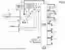
FIG. 2 is a block diagram showing the configuration of the drive system of the excavator shown in FIG. 1. In FIG. 2, a mechanical power system is indicated by double lines, a high-pressure hydraulic line is indicated by thick solid lines, pilot lines are indicated by broken lines, and an electric drive/control system is indicated by thin solid lines.
The engine 11 is a power source of the excavator 200. In the present embodiment, the engine 11 is a diesel engine employing isochronous control for maintaining the engine rotational speed constant regardless of any increase or decrease in the engine load. The amount and timing of fuel injection amount by the engine 11, and a boost pressure and the like of the engine 11 are controlled by an engine controller D7.
The engine controller D7 is a device for controlling the engine 11. In the present embodiment, the engine controller D7 executes various functions, such as an auto-idling function, an auto-idling stop function, and the like.
The auto-idling function is a function for reducing the engine rotational speed from a normal rotational speed (e.g., 2,000 rpm) to an idling rotational speed (e.g., 800 rpm) when a predetermined condition is satisfied. In the present embodiment, the engine controller D7 activates the auto-idling function in response to an auto-idling instruction from the controller 30 to reduce the engine rotational speed to the idling rotational speed.
The auto-idling stop function is a function for stopping the engine 11 when a predetermined condition is satisfied. In the present embodiment, the engine controller D7 activates the auto-idling stop function in response to an auto-idling stop instruction from the controller 30 to stop the engine 11.
A main pump 14 and a pilot pump 15 as hydraulic pumps are connected to the engine 11. A control valve 17 is connected to the main pump 14 via a high-pressure hydraulic line 16.
The control valve 17 is a hydraulic control device for controlling the hydraulic system of the excavator. Hydraulic actuators, such as a right traveling hydraulic motor 1A, a left traveling hydraulic motor 1B, the boom cylinder 7, the arm cylinder 8, the bucket cylinder 9, a rotation hydraulic motor 21, a tilt bucket cylinder 64, and the like, are connected to the control valve 17 via the high-pressure hydraulic line 16.
An operation device 26 is connected to the pilot pump 15 via a pilot line 25 and a gate lock valve D6. The control valve 17 is connected to the pilot pump 15 via a pilot line 25A and a selector valve D8. The operation device 26 includes a lever 26A, a lever 26B, and a pedal 26C. In the present embodiment, the operation device 26 is connected to the control valve 17 via a hydraulic line 27. The hydraulic line 27 is provided with a pressure reducing valve V1 that is controlled by the controller 30. The operation device 26 is connected to an operation sensor 29 via a hydraulic line 28.
The gate lock valve D6 switches between a connecting state and a disconnecting state of the pilot line 25 connecting the pilot pump 15 and the operation device 26. In the present embodiment, the gate lock valve D6 is a solenoid valve for switching between the connecting state and the disconnecting state of the pilot line 25 in response to an instruction from the controller 30. The controller 30 determines the state of the gate bar D5 based on a state signal output from the gate bar D5. When determining that the gate bar D5 is in a state of being pulled down, the controller 30 outputs a connection instruction to the gate lock valve D6. Upon receiving the connection instruction, the gate lock valve D6 is opened to bring the pilot line 25 into the connecting state. As a result, operations of the operator on the operation device 26 become effective. On the other hand, when determining that the gate bar D5 is pulled up, the controller 30 outputs a disconnection instruction to the gate lock valve D6. Upon receiving the disconnection instruction, the gate lock valve D6 is closed to bring the pilot line 25 into the disconnecting state. As a result, operations of the operator on the operation device 26 become ineffective.
The selector valve D8 switches between a connecting state and a disconnecting state of the pilot line 25A connecting the pilot pump 15 and the control valve 17. In the present embodiment, the selector valve D8 is a proportional solenoid valve for switching between the connecting state and the disconnecting state of the pilot line 25A in response to an instruction from the controller 30. In tilt and rotating operations of the bucket 6 described later, the controller 30 switches between the connecting state and the disconnecting state of the pilot line 25A by using the selector valve D8, to hydraulically drive the bucket cylinder 9 and the tilt bucket cylinder 64 or keep the bucket cylinder 9 and the tilt bucket cylinder 64 from not being hydraulically driven.
The operation sensor 29 detects the contents of operations corresponding to operations on the operation device 26. The operation sensor 29 outputs the detected contents of the operations to the controller 30.
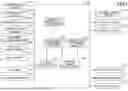
Next, various functional components provided in the controller 30 will be described with reference to FIG. 3. FIG. 3 is a functional block diagram showing the configuration of the controller 30.
In the present embodiment, the controller 30 controls the overall operation of the excavator 200.
The controller 30 receives various signals and data output from the boom angle sensor S1, the arm angle sensor S2, the bucket angle sensor S3, the machine inclination sensor S4, the bucket tilt angle sensor S5, and the input device D1. The controller 30 calculates an actual operating position of the attachment (for example, the bucket 6) based on the received signals and data. When the actual operating position of the attachment is different from the target operating position, the controller 30 transmits an alarm instruction to the sound output device D2 and the display device D3 to issue an alarm.
The controller 30 includes functional parts configured to perform various functions. In the present embodiment, the controller 30 includes, as functional parts for controlling the operation of the attachment, a target tilt angle calculation part 31, a followability determination part 32, a bucket state determination part 33, a tilt angle control part 34, and a pivoting angle control part 35.
The target tilt angle calculation part 31 calculates a direction in which and an angle by which to tilt the bucket 6 in order that a bucket line of the bucket 6 becomes parallel with the excavation target surface. The bucket line is an example of a target line according to the present disclosure, and refers to a line along a claw of the bucket 6. In the present embodiment, the bucket angle sensor S3 detects an inclination of the bucket 6 with respect to a horizontal plane. The bucket tilt angle sensor S5 detects a pivoting angle (tilt angle) of the bucket 6 about the tilt shaft 212. The angle of the excavation target surface is stored in the storage device D4 as construction information. Therefore, the target tilt angle calculation part 31 can calculate the direction in which and the angle by which to tilt the bucket 6 in order that the bucket line along the claw of the bucket 6 becomes parallel with the excavation target surface based on the detection results of the bucket angle sensor S3 and the bucket tilt angle sensor S5 and the construction information stored in the storage device D4.
In the present embodiment, the target line has been described by citing the bucket line along the claw of the bucket 6 as an example. However, the target line is not limited to the bucket line along the claw of the bucket 6. For example, the target line may include the bottom surface of the bucket 6 because the bottom surface of the bucket 6 becomes closer to the target surface than the claw of the bucket 6 is when the bucket 6 is closed. In addition, the target line may be one that passes through a predetermined position of the bucket 6.
The followability determination part 32 determines whether the bucket 6 can be tilted in the direction and by the angle calculated by the target tilt angle calculation part 31. Depending on the relative orientation of the bucket 6 with respect to the excavation target surface, it may be impossible to make the bucket line along the claw of the bucket 6 parallel with the excavation target surface even by tilting the bucket 6. For example, when there is an uphill excavation target surface in front of the excavator 200 and the bucket 6 faces sideways, the axial direction of the tilt shaft about which the bucket 6 is tilted extends frontward from the excavator 200 even when the bucket 6 faces sideways. Therefore, only by tilting the bucket 6, it is impossible to make the bucket line along the claw of the bucket 6 parallel with the excavation target surface. The followability determination part 32 determines whether or not it is possible to make the bucket line along the claw of the bucket 6 follow the excavation target surface only by tilting the bucket 6 in this way, such that the bucket line along the claw of the bucket 6 becomes parallel with the excavation target surface.
The bucket state determination part 33 determines the distance from and the orientation of the bucket 6 with respect to the excavation target surface, and determines whether or not the distance between a bottom surface 6b of the bucket 6 and the excavation target surface is equal to or less than a predetermined value. In the present embodiment, the bucket angle sensor S3 detects an inclination of the bucket 6 with respect to a horizontal plane. The boom angle sensor S1 detects an inclination of the boom 4 with respect to a horizontal plane. The arm angle sensor S2 detects an inclination of the arm 5 with respect to a horizontal plane. The machine inclination sensor S4 detects an inclination of the upper rotating body 3 with respect to a horizontal plane. The information on the excavation target surface is stored in the storage device D4 as construction information. Therefore, the bucket state determination part 33 can determine the distance from and the orientation of the bucket 6 with respect to the excavation target surface based on the detection results of the bucket angle sensor S3, the boom angle sensor S1, the arm angle sensor S2, and the machine inclination sensor S4 and the construction information stored in the storage device D4.
When the followability determination part 32 determines that it is possible to make the bucket line along the claw of the bucket 6 follow the excavation target surface such that the bucket line along the claw of the bucket 6 becomes parallel with the excavation target surface only by tilting the bucket 6, the tilt angle control part 34 tilts the bucket 6 in the direction and by the angle calculated by the target tilt angle calculation part 31. Specifically, the tilt angle control part 34 opens the selector valve D8 to bring the pilot line 25A into the connecting state, to hydraulically drive the tilt bucket cylinder 64 via the control valve 17 such that the bucket 6 is tilted in the direction and by the angle calculated by the target tilt angle calculation part 31. Further, even when the followability determination part 32 determines that it is impossible to make the bucket line along the claw of the bucket 6 parallel with the excavation target surface only by tilting the bucket 6, the tilt angle control part 34 tilts the bucket 6 to the limit to which the line along the claw of the bucket 6, which is the bucket line of the bucket 6, can become as close to parallel with the excavation target surface as possible. There is a case where the width by which the tilt angle of the bucket 6 is adjusted is set to, for example, ±45°. In this case, when the angle calculated by the target tilt angle calculation part 31 is 50°, it is impossible to make the bucket line along the claw of the bucket 6 follow the excavation target surface such that it becomes parallel with the excavation target surface only by tilting the bucket 6. Even in such a case, the tilt angle control part 34 tilts the bucket 6 by 45° that is the limit.
When the followability determination part 32 determines that it is impossible to make the bucket line along the claw of the bucket 6 follow the excavation target surface such that the bucket line along the claw of the bucket 6 becomes parallel with the excavation target surface only by tilting the bucket 6, the pivoting angle control part 35 pivots the bucket 6 by driving the bucket cylinder 9 such that the bucket line along the claw of the bucket 6 becomes parallel with the excavation target surface. Specifically, the pivoting angle control part 35 opens the selector valve D8 to bring the pilot line 25A into the connecting state, to hydraulically drive the bucket cylinder 9 via the control valve 17 such that the bucket 6 is pivoted such that the bucket line along the claw of the bucket 6 becomes parallel with the excavation target surface. Here, the pivoting angle control part 35 calculates the amount by which the bucket cylinder 9 pivots the bucket 6 for making the bucket line along the claw of the bucket 6 parallel with the excavation target surface based on the amount of tilt of the bucket 6 by the tilt angle control part 34, and pivots the bucket 6 by driving the bucket cylinder 9 by the pivoting amount.
[Operation of Excavator]
The operation of the excavator 200 configured as described above will be described below.
First, the operation of the bucket 6 will be described.
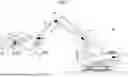
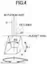
FIG. 4 is a diagram explaining the operation of the bucket 6.
The excavator 200 shown in FIG. 1 is equipped with what is generally referred to as a tilt rotator mechanism. Therefore, the bucket 6 can be pivoted not only in one direction but also in the other two directions, with respect to the arm 5.
Specifically, as shown in FIG. 4, the bucket 6 can be pivoted in a direction indicated by an arrow E1 in the drawing, which is what is generally referred to as an opening/closing direction of the bucket 6, about a bucket axis formed by a bucket pin 61. This pivoting can be realized by hydraulically driving the bucket cylinder 9.
The bucket 6 can be pivoted in a direction indicated by an arrow E2 in the drawing about a rotation axis extending in a direction connecting the arm 5 and the bucket 6.
The bucket 6 can be pivoted in a direction indicated by an arrow E3 in the drawing about a tilt axis, in a direction to tilt or deviate the bucket 6. This pivoting can be realized by hydraulically driving the tilt bucket cylinder 64.
These types of pivoting of the bucket 6 can be performed based on operations on the operation device 26, but are also performed in response to an instruction from the controller 30. As shown in FIG. 1, the tilt actuator 214 and the tilt shaft 212 are provided on the bucket 6's distal end side of the bucket cylinder 9, and the rotation motor 221 and the rotation shaft 222 are provided on the bucket 6's distal end side of the tilt shaft 212. Therefore, the tilt shaft is disposed on the distal side of the bucket shaft, and the rotation shaft is disposed at the distal side of the tilt shaft. That is, when the bucket 6 is pivoted by the bucket cylinder 9, the tilt shaft 212 and the rotation shaft 222 also rotate. Moreover, when the bucket 6 is pivoted (tilted) by the tilt actuator 214, the rotation shaft 222 also rotates.
Next, a process for enabling/disabling the control on the bucket 6 will be described.
As is often the case, the excavator 200, such as described above, switches between enabling and disabling the control on the bucket 6, from the viewpoint of construction efficiency. When the control on the bucket 6 is disabled, the excavator 200 performs construction mainly by operating the boom 4 and the arm 5. Performing construction by operating the boom 4 and the arm 5 without operating the bucket 6 makes it possible to perform the construction work quickly over a wide area because this facilitates the operation, and for other reasons. On the other hand, to excavate the excavation target surface, it is necessary to operate the bucket 6. Therefore, a control to disable the control on the bucket 6 when the bottom surface 6b of the bucket 6 is away from the excavation target surface, and to enable the control on the bucket 6 when the bottom surface 6b of the bucket 6 approaches the excavation target surface is performed.
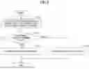
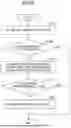
FIG. 5 is a flowchart for explaining the process for enabling/disabling the control on the bucket 6.
In this process, first, the bucket state determination part 33 determines the distance from and the orientation of the bucket 6 with respect to the excavation target surface, and calculates the distance between the bottom surface 6b of the bucket 6 and the excavation target surface (step ST11). Here, as described above, the bucket angle sensor S3 detects the inclination of the bucket 6 with respect to a horizontal plane, the boom angle sensor S1 detects the inclination of the boom 4 with respect to a horizontal plane, and the arm angle sensor S2 detects the inclination of the arm 5 with respect to a horizontal plane. In addition, the machine inclination sensor S4 detects the inclination of the upper rotating body 3 with respect to a horizontal plane, and the information on the excavation target surface is stored in the storage device D4 as construction information. Therefore, the bucket state determination part 33 can determine the distance from and the orientation of the bucket 6 with respect to the excavation target surface based on the detection results of the bucket angle sensor S3, the boom angle sensor S1, the arm angle sensor S2, and the machine inclination sensor S4 and the construction information stored in the storage device D4.
Then, the bucket state determination part 33 determines whether or not the distance between the bottom surface 6b of the bucket 6 and the excavation target surface is equal to or less than a predetermined value (step ST12). When the distance between the bottom surface 6b of the bucket 6 and the excavation target surface is not equal to or less than the predetermined value (NO in step ST12), the controller 30 disables the control on the bucket 6 (step ST13). In the state in which the control on the bucket 6 is disabled, pivoting of the bucket 6 by the bucket cylinder 9 is not performed. Of the tilt angle control part 34 and the pivoting angle control part 35, the tilt angle control part 34 is enabled to tilt the bucket 6, but the pivoting angle control part 35 is disabled to pivot the bucket 6 by driving the bucket cylinder 9. In this case, the controller 30 enters a first mode in which the angle formed between the arm 5 and the bucket 6 is kept constant regardless of the angle formed between the bottom surface 6b of the bucket 6 and the excavation target surface. In the first mode, work such as excavation of the excavation target surface, or the like is performed.
On the other hand, when the distance between the bottom surface 6b of the bucket 6 and the excavation target surface is equal to or less than the predetermined value (YES in step ST12), the controller 30 enables the control on the bucket 6 (step ST14). In a state in which the control on the bucket 6 is enabled, pivoting of the bucket 6 by driving the bucket cylinder 9 is enabled. Of the tilt angle control part 34 and the pivoting angle control part 35, the tilt angle control part 34 is enabled to tilt the bucket 6 and the pivoting angle control part 35 is also enabled to pivot the bucket 6 by driving the bucket cylinder 9. In this case, the controller 30 enters a second mode in which the angle formed between the arm 5 and the bucket 6 is changeable, and the angle formed between the claw of the bucket 6 and the excavation target surface is kept constant. In the second mode, for example, work such as leveling of the excavation target surface, or the like is performed.
In this way, the control on the bucket 6 is enabled or disabled based on the distance between the bottom surface 6b of the bucket 6 and the excavation target surface.
Note that when a machine control function of the controller 30 is disabled, the control on the bucket 6 is disabled.
On the other hand, when the machine control function of the controller 30 is enabled and it is permitted to operate the bucket 6, the control on the bucket 6 by the pivoting angle control part 35 is enabled as long as the distance between the bottom surface 6b of the bucket 6 and the excavation target surface is equal to or less than the predetermined value as described above. Therefore, the angle formed between the bottom surface 6b of the bucket 6 and the excavation target surface is controlled to be constant.
Even when the machine control function of the controller 30 is enabled and it is permitted to operate the bucket 6, unless the distance between the bottom surface 6b of the bucket 6 and the excavation target surface is equal to or less than the predetermined value, the control on the bucket 6 by the pivoting angle control part 35 is disabled, and the angle formed between the arm 5 and the bucket 6 is kept constant.
Next, a process for making the claw line of the bucket 6 parallel with the excavation target surface by pivoting the bucket 6 when it is impossible to make the claw line of the bucket 6 parallel with the excavation target surface only by tilting the bucket 6 will be described.
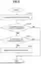
FIG. 6 is a flowchart for explaining a process for making the bucket line along the claw of the bucket 6 parallel with the excavation target surface by pivoting the bucket 6.
In this process, first, the target tilt angle calculation part 31 calculates a direction in which and an angle by which to tilt the bucket 6 in order to make the bucket line along the claw of the bucket 6 parallel with the excavation target surface (step ST21). Here, the bucket angle sensor S3 detects the inclination of the bucket 6 with respect to a horizontal plane, and the bucket tilt angle sensor S5 detects the rotation angle of the bucket 6 about the tilt axis. The angle of the excavation target surface is stored in the storage device D4 as construction information. Therefore, the target tilt angle calculation part 31 can calculate the direction in which and the angle by which to tilt the bucket 6 in order to make the bucket line along the claw of the bucket 6 parallel with the excavation target surface based on the detection results of the bucket angle sensor S3 and the bucket tilt angle sensor S5 and the construction information stored in the storage device D4.
Next, the followability determination part 32 determines whether or not it is possible to tilt the bucket 6 in the direction and by the angle calculated by the target tilt angle calculation part 31 (step ST22). As described above, depending on the relative orientation of the bucket 6 with respect to the excavation target surface, it may be impossible to make the claw line of the bucket 6 parallel with the excavation target surface even by tilting the bucket 6. Therefore, the followability determination part 32 determines whether or not it is possible to make the bucket line along the claw of the bucket 6 parallel with the excavation target surface only by tilting the bucket 6.
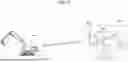
FIG. 7 is a view showing an example of a situation in which it is impossible to make the bucket line along the claw of the bucket 6 parallel with the excavation target surface even by tilting the bucket 6.
As shown in FIG. 7, when there is an uphill excavation target surface GL in front of the excavator 200 and the bucket 6 faces sideways, the axial direction of a tilt shaft A1 about which the bucket 6 is tilted extends in the front-rear direction of the excavator 200 even when the bucket 6 faces sideways. Therefore, it is impossible to make the bucket line along a claw 6a of the bucket 6 parallel with the excavation target surface GL only by tilting the bucket 6.
Therefore, when it is impossible to tilt the bucket 6 in the direction and by the angle calculated by the target tilt angle calculation part 31 (NO in step ST22), the controller 30 first determines whether or not it is in the first mode, in which the pivoting angle control part 35 is disabled to control the bucket 6 by driving the bucket cylinder 9 (step ST23).
In the first mode in which the pivoting angle control part 35 is disabled to control the bucket 6 by driving the bucket cylinder 9, as described above, the pivoting angle control part 35 is disabled to pivot the bucket 6, although the tilt angle control part 34 is enabled to tilt the bucket 6. Therefore, when it is impossible to tilt the bucket 6 in the direction and by the angle calculated by the target tilt angle calculation part 31, it is impossible to make the bucket line along the claw 6a of the bucket 6 parallel with the excavation target surface GL. For example, when the construction is performed by erecting the claw 6a of the bucket 6 on the excavation target surface GL, the control on the bucket 6 is disabled because the bottom surface 6b of the bucket 6 is away from the excavation target surface GL. When it is impossible to tilt the bucket 6 in the direction and by the angle calculated by the target tilt angle calculation part 31 in this state, it is impossible to make the bucket line along the claw 6a of the bucket 6 parallel with the excavation target surface GL, and to perform the construction.
Therefore, when the control on the bucket 6 by the pivoting angle control part 35 is disabled (YES in step ST23), the controller 30 enables the pivoting angle control part 35 to control the bucket 6 by driving the bucket cylinder 9 (step ST24). In this case, the controller 30 enters a third mode for making the bucket line along the claw 6a of the bucket 6 parallel with the excavation target surface GL.
Then, the tilt angle control part 34 tilts the bucket 6 to the limit, and the pivoting angle control part 35 pivots the bucket 6 until the bucket line along the claw 6a of the bucket 6 becomes parallel with the excavation target surface GL. Here, the pivoting angle control part 35 calculates the amount by which to pivot the bucket 6 in order to make the bucket line along the claw 6a of the bucket 6 parallel with the excavation target surface GL based on the amount by which the bucket 6 is tilted by the tilt angle control part 34, and pivots the bucket 6 by driving the bucket cylinder 9 by the amount of pivoting.
As described above, according to the present embodiment, in the excavator 200 including the arm 5 pivotally attached to the boom 4 pivotally attached to the upper rotating body 3, the bucket 6 pivotally attached to the arm 5, and the controller 30 for controlling the operations of the boom 4, the arm 5, and the bucket 6, the controller 30 has the first mode for keeping the angle formed between the arm 5 and the bucket 6 constant, the second mode for keeping the angle formed between the excavation target surface and the bottom surface 6b of the bucket 6 constant, and the third mode for making the bucket line of the bucket 6 parallel with the excavation target surface.
FIG. 8 is a view showing an example of a situation in which the bucket line along the claw 6a of the bucket 6 is made parallel with the excavation target surface by pivoting the bucket 6. As shown in FIG. 8, when there is an uphill excavation target surface GL in front of the excavator 200 and the bucket 6 faces sideways, the axial direction of a bucket shaft A2 about which the bucket 6 is pivoted is perpendicular to the front-rear direction of the excavator 200 even when the bucket 6 faces sideways. Therefore, by pivoting the bucket 6, it is impossible to make the bucket line along the claw 6a of the bucket 6 parallel with the excavation target surface GL.
When it is possible to tilt the bucket 6 in the direction and by the angle calculated by the target tilt angle calculation part 31 (YES in step ST22), it is not necessary to enable the control on the bucket 6. Moreover, when the control on the bucket 6 has been enabled in the first place (NO in step ST23), it is not necessary to re-enable the control on the bucket 6.
In this way, even in the configuration for disabling the control on the bucket 6 when the bottom surface 6b of the bucket 6 and the excavation target surface are away from each other from the viewpoint of construction efficiency, the control on the bucket 6 is temporarily enabled when it is impossible to make the bucket line along the claw 6a of the bucket 6 parallel with the excavation target surface only by tilting the bucket 6, to make it possible to perform the construction work on the excavation target surface by the claw 6a of the bucket 6.
As described above, in the present embodiment, in order to control the excavator 200 including the arm 5 pivotally attached to the boom 4 pivotally attached to the upper rotating body 3, the bucket 6 pivotally attached to the arm 5, the tilt mechanism 23 for tilting the bucket 6 with respect to the arm 5, and the bucket cylinder 9 for pivoting the bucket 6 with respect to the arm 5, provided is the controller 30 configured to make the tilting of the bucket 6 by the tilt mechanism 23 and the pivoting of the bucket 6 by the bucket cylinder 9 simultaneously operable such that the bucket line of the bucket 6 becomes parallel with the excavation target surface. Thus, the efficiency of the construction work can be improved. Here, with the controller 30 provided with the first mode for keeping the angle formed between the arm 5 and the bucket 6 constant, the second mode for keeping the angle formed between the excavation target surface and the bottom surface 6b of the bucket 6 constant, and the third mode for making the bucket line of the bucket 6 parallel with the excavation target surface, it is possible to bring about efficiency to the construction work by the controller 30 switching among the modes.
Further, when the controller 30 has failed to make the bucket line of the bucket 6 parallel with the excavation target surface by tilting the bucket 6 via the tilt mechanism 23, the controller 30 makes the pivoting of the bucket 6 by the bucket cylinder 9 operable such that the bucket line of the bucket 6 becomes parallel with the excavation target surface. Thus, even when it is impossible to make the line of the claw 6a of the bucket 6 parallel with the excavation target surface only by tilting the bucket 6, it is possible to make the line of the claw 6a of the bucket 6 parallel with the excavation target surface by making the line of the claw 6a of the bucket 6 follow the excavation target surface by pivoting the bucket 6.
Further, when a predetermined condition is satisfied, the controller 30 makes the tilting of the bucket 6 by the tilt mechanism 23 and the pivoting of the bucket 6 by the bucket cylinder 9 simultaneously operable. With such a configuration, it is possible to make the tilting of the bucket 6 by the tilt mechanism 23 and the pivoting of the bucket 6 by the bucket cylinder 9 simultaneously operable only when necessary.
Here, as described above, the configuration for disabling the bucket 6 is provided from the viewpoint of construction efficiency. Therefore, it is preferable that the disabling is temporary. A process for disabling the previously enabled control on the bucket 6 will be described below.
FIG. 9 is a flowchart for explaining the process for disabling the previously enabled control on the bucket 6.
In this process, first, similarly to the process in step ST21, the target tilt angle calculation part 31 calculates the direction in which and the angle by which to tilt the bucket 6 such that the line along the claw of the bucket 6, which is the bucket line of the bucket 6, becomes parallel with the excavation target surface (step ST31).
Next, similarly to the process in step ST22, the followability determination part 32 determines whether or not it is possible to tilt the bucket 6 in the direction and by the angle calculated by the target tilt angle calculation part 31 (step ST32).
When it is possible to tilt the bucket 6 in the direction and by the angle calculated by the target tilt angle calculation part 31 (YES in step ST32), similarly to the process in step ST11, the bucket state determination part 33 determines the distance from and the orientation of the bucket 6 with respect to the excavation target surface, and calculates the distance between the bottom surface 6b of the bucket 6 and the excavation target surface (step ST33).
Similarly to the process in step ST12, the bucket state determination part 33 determines whether or not the distance between the bottom surface 6b of the bucket 6 and the excavation target surface is equal to or less than the predetermined value (step ST34), and when the distance between the bottom surface 6b of the bucket 6 and the excavation target surface is not equal to or less than the predetermined value (NO in step ST34), disables the control on the bucket 6 (step ST35).
On the other hand, when it is impossible to tilt the bucket 6 in the direction and by the angle calculated by the target tilt angle calculation part 31 (NO in step ST32), the control on the bucket 6 is not disabled because it is impossible to make the bucket line along the claw of the bucket 6 parallel with the excavation target surface unless the bucket 6 is pivoted.
When the distance between the bottom surface 6b of the bucket 6 and the excavation target surface is equal to or less than the predetermined value (YES in step ST34), the control on the bucket 6 is not disabled because the condition for enabling the control on the bucket 6 has been satisfied in the first place.
Thus, when the predetermined condition is no longer satisfied, the controller 30 disables the pivoting of the bucket 6 by the bucket cylinder 9. Thus, when the predetermined condition is no longer satisfied, it is possible to improve the construction efficiency by disabling the control on the bucket 6.
The excavator 200 may be configured to electrically drive one or more, or all of the driving-target components, such as the lower traveling body 1, the upper rotating body 3, the boom 4, the arm 5, the bucket 6, and the like, by electric actuators. That is, the excavator 200 may be a hybrid excavator or an electric excavator.
Other Embodiments
Instead of or in addition to being operable by an operator riding in the cabin 10, the excavator 200 may be remotely operable from outside the excavator 200. When the excavator 200 is remotely operated, the interior of the cabin 10 may be unoccupied.
FIG. 10 is a view showing an example of a system in which the excavator 200 is remotely operated.
As shown in FIG. 10, the excavator 200 may be operated in the remote control chamber RC.
A remote control chamber RC is equipped with a remote controller 40, a sound output device RD2, an indoor imaging device RC1, a display device RD3, a communication device T, and the like. The remote control chamber RC is mounted with a driver's seat DS to be seated by an operator OP who remotely operates the excavator 200.
The remote controller 40 is an example of a control device according to the present disclosure, and is an arithmetic device for executing various types of arithmetic operations. In the present embodiment, like the controller 30, the remote controller 40 is composed of a microcomputer including a CPU and a memory. Various functions of the remote controller 40 are realized by the CPU executing a program stored in the memory.
The sound output device RD2 is configured to output a sound. In the present embodiment, the sound output device RD2 is a loudspeaker and is configured to reproduce a sound collected by a sound collecting device (not shown) attached to the excavator 200.
The indoor imaging device RC1 is configured to image the interior of the remote control chamber RC. In the present embodiment, the indoor imaging device RC1 is a camera installed inside the remote control chamber RC and is configured to capture images of the operator OP seated on the driver's seat DS.
The communication device T is configured to control wireless communication with a communication device (not shown) attached to the excavator 200.
A remote control device 126 including an engine rotational speed adjustment dial 75 is provided near the driver's seat DS. The engine rotational speed adjustment dial 75 is a dial for adjusting the engine rotational speed of the engine 11 and is configured to switch the engine rotational speed over four stages, namely, for example, an SP mode, an H mode, an A mode, and an idling mode. The remote control device 126 is provided with an operation sensor 129 for detecting the contents of operations on the remote control device 126. Thus, the contents of operations on the remote control device 126 can be detected. The sensor for detecting operations on the remote control device 126 may be not only a pressure sensor for detecting pressures on to the remote control device 126, but also, for example, a tilt sensor for detecting the tilt angle of an operation lever, an angle sensor for detecting the swing angle of an operation lever about the swing shaft, and the like. The sensor for detecting operations on the remote control device 126 may be composed of any other sensor, such as a pressure sensor, a current sensor, a voltage sensor, a distance sensor, and the like. The operation sensor 129 outputs a detected pressure value to the remote controller 40. The remote controller 40 generates an operation signal based on the received pressure value and transmits the generated operation signal toward the excavator 200.
The display device RD3 is configured to display information on the surrounding conditions of the excavator 200. In the present embodiment, the display device RD3 is a multi-display composed of nine monitors having three vertical columns and three horizontal rows, and is configured to display the state of the space in front of, on the left of, and on the right of the excavator 200. Each monitor is a liquid crystal monitor, an organic EL monitor, or the like. The display device RD3 may be composed of one or a plurality of curved monitors or of a projector.
The display device RD3 may be a display device that can be worn by the operator OP. For example, the display device RD3 may be a head-mounted display and may be configured to exchange information with the remote controller 40 by wireless communication. The head-mounted display may be wire-connected to the remote controller 40. The head-mounted display may be a transmissive head-mounted display or a non-transmissive head-mounted display. The head-mounted display may be a monocular head-mounted display or a binocular type head-mounted display.
The display device RD3 is configured to display an image that enables the operator OP present in the remote control chamber RC to visually recognize the surroundings of the excavator 200. That is, the display device RD3 displays the image so as to enable the operator to confirm the surroundings of the excavator 200 as if the operator was in the cabin 10 of the excavator 200, even though the operator is in the remote control chamber RC.
Also in the remote control chamber RC configured in this way, the remote controller 40 may have the functions of the functional parts of the controller 30 of the excavator 200, including the target tilt angle calculation part 31, the followability determination part 32, the bucket state determination part 33, the tilt angle control part 34, and the pivoting angle control part 35, and may execute the automatic bucket tilt control described above.
Claims
What is claimed is:1. An excavator, comprising:
a self-propelled lower traveling body;
an upper rotating body rotatably provided on the lower traveling body;
an arm pivotally attached to a boom pivotally attached to the upper rotating body;
a bucket pivotally attached to the arm;
a tilt mechanism configured to tilt the bucket with respect to the arm;
a pivoting mechanism configured to pivot the bucket with respect to the arm; and
a control device including a processor and a memory, and configured to make tilting of the bucket by the tilt mechanism and pivoting of the bucket by the pivoting mechanism simultaneously operable in order to make a target line passing through a predetermined position of the bucket parallel with an excavation target surface.
2. The excavator according to claim 1,
wherein the target line is a bucket line along a claw of the bucket.
3. The excavator according to claim 1,
wherein when the tilting of the bucket by the tilt mechanism fails to make the target line of the bucket parallel with the excavation target surface, the control device makes the pivoting of the bucket by the pivoting mechanism operable in order to make the target line of the bucket parallel with the excavation target surface.
4. The excavator according to claim 1,
wherein when a predetermined condition is satisfied, the control device makes the tilting of the bucket by the tilt mechanism and the pivoting of the bucket by the pivoting mechanism simultaneously operable.
5. The excavator according to claim 4,
wherein when the predetermined condition is no longer satisfied, the control device makes the pivoting of the bucket by the pivoting mechanism inoperable.
6. An excavator, comprising:
an arm pivotally attached to a boom pivotally attached to a rotating body;
a bucket pivotally attached to the arm; and
a control device including a processor and a memory, and configured to control operations of the boom, the arm, and the bucket,
wherein the control device has:
a first mode for keeping an angle formed between the arm and the bucket constant;
a second mode for keeping an angle formed between an excavation target surface and a bottom surface of the bucket constant; and
a third mode for making a target line passing through a predetermined position of the bucket parallel with the excavation target surface.
7. A control device of an excavator,
wherein the excavator includes:
an arm pivotally attached to a boom pivotally attached to a rotating body;
a bucket pivotally attached to the arm;
a tilt mechanism configured to tilt the bucket with respect to the arm, and
a pivoting mechanism configured to pivot the bucket with respect to the arm,
the control device comprising: a processor and a memory, and configured to make tilting of the bucket by the tilt mechanism and pivoting of the bucket by the pivoting mechanism simultaneously operable.
Images & Drawings included:
Sources:
- United States Patent and Trademark Office - verify current appl. status at the USPTO↗
Similar patent applications:
- » 20200385958
Work machine control device, excavating machine control device, and work machine control method - » 20250207364
EXCAVATOR AND CONTROL DEVICE FOR EXCAVATOR - » 20250188704
EXCAVATOR AND CONTROL DEVICE FOR EXCAVATOR - » 20240309603
EXCAVATOR AND METHOD AND DEVICE FOR CONTROLLING EXCAVATOR - » 20080300757
Excavator control mode switching device and excavator - » 20240271393
METHOD AND DEVICE FOR CONTROLLING EXCAVATOR - » 20060156716
Travel control device for excavators - » 20250129566
CONTROL DEVICE FOR EXCAVATOR - » 20130268166
ENGINE IDLING CONTROL DEVICE OF EXCAVATOR AND METHOD THEREOF - » 20250283301
CONTROL DEVICE FOR EXCAVATOR
Recent applications in this class:
- » 20260098393 2026-04-09
CONTROL DEVICE, CONTROL METHOD, AND WORK MACHINE - » 20260062885 2026-03-05
WORK MACHINE - » 20260028793 2026-01-29
WORK MACHINE - » 20260015819 2026-01-15
WORK MACHINE INTERFACE FOR SELECTING A WORK LEVEL OF WORK MACHINE - » 20250333926 2025-10-30
EXCAVATOR AND EXCAVATOR OPERATION SYSTEM - » 20250263902 2025-08-21
HYDRAULIC CONTROL SYSTEM IN WORKING MACHINES - » 20250263901 2025-08-21
CONTROL SYSTEM AND CONTROL METHOD FOR LOADING MACHINE - » 20250207352 2025-06-26
SHOVEL - » 20250179762 2025-06-05
ASSISTANCE DEVICE, WORK MACHINE, AND ASSISTANCE SYSTEM - » 20250163670 2025-05-22
WORKING MACHINE