ARTIFICIAL EYELASH PRODUCT, ARTIFICIAL EYELASH KIT AND MANUFACTURING METHOD THEREFOR
US20260114531A1
2026-04-30
19/400,932
2025-11-25
Smart Summary: An artificial eyelash product consists of a base that sticks to the area around the eye. This base holds several groups of eyelashes that can be attached to the user's eyelids. Each group has a part that connects to the base, with multiple eyelashes extending from it. A kit is also available that includes everything needed to use these artificial eyelashes. There is a specific method for making these eyelashes and their components. 🚀 TL;DR
Abstract:
An artificial eyelash product, a method for manufacturing the artificial eyelash product, and an artificial eyelash kit are provided. The artificial eyelash product includes an auxiliary substrate configured for attachment to an eye region of a user; and a plurality of eyelash clusters coupled to the auxiliary substrate. Each eyelash cluster being capable of being attached to the eye region of the user. At least one eyelash cluster includes a root region affixed to the auxiliary substrate; and a plurality of eyelashes extending from the root region.
Assignee:
- Qingdao Futesen Plastic Technology Co., Ltd 1 🇨🇳 QINGDAO, SD, China
Applicant:
Interested in similar patents?
Get notified when new applications in this technology area are published.
Classification:
A41G5/02 » CPC main
Hair pieces, inserts, rolls, pads, or the like; Toupées Artificial eyelashes; Artificial eyebrows
Description
CROSS REFERENCE TO RELATED DISCLOSURES
This application is a continuation-in-part of U.S. application Ser. No. 19/215,247, filed on May 21, 2025, which is a continuation-in-part of U.S. application Ser. No. 18/679,291, filed on May 30, 2024, which claims foreign priority of Chinese Patent disclosure No. 202410596438.4, filed on May 14, 2024 in the China National Intellectual Property Administration, the disclosures of all of which are hereby incorporated by references.
TECHNICAL FIELD
The present disclosure relates to the technical field of cosmetic and makeup products, and more particularly to an artificial eyelash product that is suitable for both grafted and self-wear applications. The disclosure further provides a corresponding method for manufacturing the artificial eyelash product and an artificial eyelash kit including the artificial eyelash product.
BACKGROUND
In recent years, because of their convenient and aesthetically pleasing characteristics, artificial eyelash products have become more and more popular among women and have become an essential makeup product. Current artificial eyelash products are generally categorized into two types: grafted eyelashes and self-wear eyelashes. Grafted eyelashes, also known as “cluster lashes,” are composed of individual clusters applied one by one. This approach is favored by professional lash technicians due to its precision and adaptability to various eye shapes. However, it requires skill, time, and specialized tools, limiting its practicality for everyday users. In contrast, self-wear eyelashes are typically manufactured as a one-piece strip or sheet, allowing users to apply them easily without professional assistance. While more convenient and time-saving, self-wear types often lack the styling flexibility and natural appearance of cluster lashes. Their fixed shape also reduces adaptability to different eye contours and personal preferences.
Despite growing consumer demand for products that are both user-friendly and customizable, there is an ongoing challenge in the field of artificial eyelash products to develop a solution that effectively integrates the advantages of both grafted (cluster-type) and self-wear (strip-type) eyelashes.
SUMMARY
The present disclosure provides an artificial eyelash product, a corresponding method for manufacturing the artificial eyelash product, and an artificial eyelash kit including the artificial eyelash product. The artificial eyelash product is configured to be soft, comfortable, and easy to use, and is suitable for both professional grafting and self-wear by consumers.
In a first aspect, the present disclosure provides an artificial eyelash product, including an auxiliary substrate configured for attachment to an eye region of a user, and a plurality of eyelash clusters coupled to the auxiliary substrate. Each eyelash cluster being capable of being attached to the eye region of the user. At least one eyelash cluster includes a root region affixed to the auxiliary substrate and a plurality of eyelashes extending from the root region
In a second aspect, the present disclosure provides a method for manufacturing an artificial eyelash product, including: arranging a plurality of eyelashes into a root region; bonding the plurality of eyelashes at the root region to form an eyelash cluster; and coupling a plurality of eyelash clusters to an auxiliary substrate configured for attachment to an eye region of a use. Each eyelash cluster of the plurality of eyelash clusters is capable of being attached to the eye region of the user.
In a third aspect, the present disclosure provides an artificial eyelash kit, including: an auxiliary substrate configured for attachment to an eye region of a user, a plurality of eyelash clusters coupled to the auxiliary substrate, each eyelash cluster being capable of being attached to the eye region of the user, wherein at least one eyelash cluster comprises a root region affixed to the auxiliary substrate and a plurality of eyelashes extending from the root region; and an applicator tool configured to position or attach the eyelash cluster to the eye region of the user.
The present disclosure provides an artificial eyelash product that is adaptable for multiple modes of application. The product supports both professional grafting, enabled by its clustered eyelash structure including a root region, and self-wear use by consumers, facilitated by its auxiliary substrate configured to improved handling and positioning. Such a configuration enables a single artificial eyelash product to be applied in either manner, thereby enhancing compatibility across different usage scenarios and reducing the need for separate product types.
In summary, the present disclosure provides improved artificial eyelash products, corresponding methods for manufacturing such product, and artificial eyelash kits including the artificial eyelash product. By enabling compatibility with both grafting and self-wear approaches, the disclosed structures may provide enhanced usability and manufacturing flexibility compared with conventional eyelash products.
BRIEF DESCRIPTION OF THE DRAWINGS
FIG. 1A is a flowchart illustrating the manufacturing method of an artificial eyelash product, according to an embodiment of the present disclosure.
FIG. 1B is a flowchart illustrating the manufacturing method of an artificial eyelash product using ultrasonic welding, according to an embodiment of the present disclosure.
FIG. 2A is a top view schematic diagram showing the structure of an eyelash cluster, according to an example of the present disclosure.
FIG. 2B is a side view schematic diagram showing the structure of an eyelash cluster, according to an example of the present disclosure.
FIG. 3 is a schematic diagram illustrating an eyelash cluster sheet, according to an example of the present disclosure.
FIG. 4 is a schematic diagram illustrating a semi-finished product, according to an example of the present disclosure.
FIG. 5 is a schematic structural diagram of an artificial eyelash product, according to an example of the present disclosure.
FIG. 6 is a schematic structural diagram of an artificial eyelash product, according to an example of the present disclosure.
FIG. 7 is a schematic structural diagram of an ultrasonic welding machine, according to an example of the present disclosure.
FIG. 8 is a schematic diagram illustrating an artificial eyelash kit, according to an example of the present disclosure.
DETAILED DESCRIPTION OF THE EMBODIMENTS
The technical solutions in the embodiments of the present disclosure will be described clearly and completely with reference to the accompanying drawings in the embodiments of the present disclosure. Obviously, the described embodiments are only a part of the embodiments of the present disclosure rather than all of them. Based on the embodiments in the present disclosure, all other embodiments obtained by those skilled in the art without creative work shall fall within the scope of protection of the present disclosure.
It should be noted that all directional indications (such as up, down, left, right, front, back) in the embodiments of the present disclosure are merely used to explain relative position relationships or motion conditions between the components in a specific attitude (as shown in the drawings). The directional indication changes as the specific attitude changes.
It should be noted that when an element is described as “being fixed on” or “being arranged on” another element, the element may be directly arranged on the another element or there may be an intermediate element. When an element is described as “being connected to” another element, the element may be directly connected to the another element or there may be an intermediate element.
Moreover, the terms “first”, “second”, and the like in the present disclosure are merely used for description and cannot be understood as indicating or implying their relative importance or as implicitly indicating the quantity of the technical features indicated. Thus, the feature defined by “first” or “second” may explicitly or implicitly include at least one such feature. In addition, the technical solutions of various embodiments may be combined with each other, but must be based on that the combined technical solutions can be implemented by those skilled in the art. When the combination of the technical solutions is contradictory or impossible to realize, it shall be considered that such combination does not exist and is not within the scope of protection of the present disclosure.
FIG. 1A is a flowchart 100A illustrating a method for manufacturing an artificial eyelash product, according to an embodiment of the present disclosure. The method includes a sequence of steps designed to produce an eyelash product suitable for both grafted and self-wear applications.
At step 102A, the method begins with arranging a plurality of eyelashes into a root region. A plurality of artificial eyelashes is arranged such that their proximal ends are aligned to define a root region. The eyelashes may be arranged into a fan-shaped, tapered, or bundled configuration to achieve a desired volumetric and aesthetic characteristic. The number, material, and length of the eyelashes may be varied based on design specifications. During arrangement, the eyelashes may be held in position using a jig, mold, clamp, or other temporary support fixture. As used herein, the term “root region” may also be referred to as the “base region”, “bonding region,” or “attachment portion.” The root region refers to the portion of an eyelash cluster at which the individual eyelash filaments are joined or bound together. In various examples, the root region may include an adhesive band, fused section, filament, or strip, or molded polymer segment, or any other suitable structure configured to provide a structural base for the cluster. The root region may be configured to adhere to, bound to, or be couple to an auxiliary substrate. The root region may have a width, thickness, or flexibility selected to conform to the curvature of the user's eyelid while maintaining stable attachment. As used herein, “eyelash cluster” refers to a group of one or more eyelash filaments joined at the root region.
In some examples, the material of the eyelashes may be selected from synthetic, natural, or composite fibers, depending on desired performance characteristics. Suitable synthetic materials may include polybutylene terephthalate (PBT), polyester, nylon, polyurethane-based fibers, acrylic fibers, polypropylene, polyethylene, cellulose-based fibers, or combinations thereof. In other examples, the eyelashes may be formed from natural materials such as silk fibers, human hair, animal-derived fibers, or plant-based filaments. Composite or specialty fibers may also be used, including fibers having matte or glossy finishes, pre-tinted fibers, textured fibers, heat-resistant fibers, hollow-core fibers for reduced weight, or fibers having non-circular cross-sections such as flat, oval, triangular, or multi-lobed profiles. The selected material may influence flexibility, softness, color retention, curl stability, and overall durability of the resulting eyelash cluster.
At step 104A, the method includes bonding the plurality of eyelashes at the root region to form an eyelash cluster. In some examples, bonding is achieved using a localized thermal process, such as ultrasonic welding, thermal melting, or laser bonding, which softens or melts at least a portion of the fiber material and/or an added bonding material so that the proximal ends fuse together upon cooling. For example, ultrasonic welding may be performed by pressing the root region against an anvil while an ultrasonic horn applies vibrational energy at a selected frequency and amplitude. As another example, thermal melting may be performed using a heated plate, hot wire, hot air stream, or contact heater brought into contact or proximity with the root region.
In some examples, bonding may be achieved using mechanical crimping, in which the root region is compressed by a crimping tool, die, or clamp to mechanically interlock the fibers. In some examples, chemical bonding or adhesive attachment may be used, in which a bonding agent such as a thermosetting resin, UV-curable resin, hot-melt adhesive, solvent-based adhesive, water-based adhesive, cyanoacrylate adhesive, silicone-based adhesive, or other polymeric binder is applied to the proximal ends. The bonding agent may be dispensed by dipping, spraying, brushing, jetting, or micro-dispensing directly onto the root region, followed by curing through heat, UV radiation, ambient drying, or other curing mechanisms.
At step 106A, the method includes coupling a plurality of eyelash clusters to an auxiliary substrate configured for attachment to an eye region of a user, where each eyelash cluster of the plurality of eyelash clusters is capable of being attached to the eye region of the user. The auxiliary substrate may include a supporting structure formed in the shape of a strip, sheet, block, flake, film, band, partial arc, segmented piece, or any other geometry suitable for positioning the eyelash clusters. As used herein, the term “eye region” broadly refers to the portion of a user's face in proximity to the eye, including, without limitation, the upper or lower eyelid, the lash line, the skin immediately adjacent to the eyelashes, or any region suitable for attachment of artificial eyelash products. In various embodiments, the eye region may correspond to (i) the outer surface of the upper eyelid, (ii) the natural lash line where native eyelashes emerge, or (iii) a skin area immediately above or below the natural lash line. The precise location may vary depending on the design of the auxiliary substrate, attachment mechanism (e.g., adhesive, magnetic, or mechanical clip), and the desired aesthetic effect. As used herein, the term “auxiliary substrate” refers to any supporting structure configured to carry and position eyelash clusters, and may include films, strips, sheets, bands, molded structures, or combinations thereof. The auxiliary substrate may be flexible, semi-rigid, or rigid unless otherwise specified.
In some examples, the auxiliary substrate or supporting structure may be formed from flexible or semi-rigid materials suitable for carrying and positioning the eyelash clusters. The supporting structure may comprise polyester, polyurethane, nylon, cotton, silk, cellulose-based fibers, thermoplastic elastomers, or composites thereof. These materials may be provided in the form of films, sheets, woven or non-woven fabrics, laminates, molded components, or other structural formats. In some examples, the supporting structure may further include magnetically responsive materials or discrete magnetic components configured to interact with magnetic eyeliner or other magnetic attachment systems. In other examples, the supporting structure may incorporate a pressure-sensitive adhesive layer, a repositionable adhesive layer, or a heat-activated adhesive layer on a surface intended to contact the user's skin or natural lashes. Such material selections allow the auxiliary substrate to achieve desired flexibility, comfort, durability, and attachment performance across various application modes.
In some examples, the auxiliary substrate may have a colored, translucent, or transparent appearance. For instance, the supporting structure may be formed from materials that inherently provide such optical properties, such as clear polyester films, tinted polyurethane films, translucent silicone-based materials, or transparent thermoplastic elastomers. In other examples, pigments, dyes, or colorants may be added to the substrate material to achieve a desired hue or visual effect, or the substrate may be surface-treated or coated to adjust its optical characteristics. Providing a colored, translucent, or transparent auxiliary substrate may improve aesthetic integration with the user's skin tone, reduce visual detectability during wear, or enhance the appearance of the eyelash clusters.
In some examples, coupling the eyelash clusters to the auxiliary substrate may be performed by directly attaching the root region of each cluster to a surface of the auxiliary substrate. The attachment may be achieved using adhesive bonding, thermal lamination, ultrasonic welding, or combinations thereof.
In some examples, an eyelash cluster sheet may be used as an intermediate carrier, and coupling the plurality of eyelash clusters to the auxiliary substrate may include first attaching the eyelash clusters to the eyelash cluster sheet and then affixing the eyelash cluster sheet to the auxiliary substrate. As used herein, the term “eyelash cluster sheet” refers to any temporary or permanent carrier structure configured to support multiple eyelash clusters during assembly or use, and may include adhesive substrates, films, tapes, or other sheet-like structures. For example, the eyelash clusters may be attached to the eyelash cluster sheet using adhesive bonding, thermal lamination, ultrasonic welding, or combinations of these techniques. The eyelash cluster sheet may then be affixed to the auxiliary substrate using adhesive bonding, thermal lamination, ultrasonic welding, or combinations thereof. This two-stage attachment process may facilitate automated placement, improve positional accuracy, and enhance overall production efficiency.
In some examples, the eyelash clusters may be arranged on the auxiliary substrate in a variety of patterns to achieve different styling effects. For example, the clusters may be positioned with uniform spacing to create a natural appearance, or placed at varying intervals to form gradient, cat-eye, doll-eye, or wispy configurations. In some examples, at least two eyelash clusters may be positioned in an interlaced, overlapped, stacked, or layered manner to provide increased volume, multidimensional texture, or enhanced visual depth. The clusters may be oriented at different angles, fan widths, curl levels, or lengths to create hybrid or mixed-style arrangements. Automated placement equipment, alignment guides, vision-based positioning systems, or mechanical fixtures may be used to ensure consistent cluster positioning along the auxiliary substrate. Such flexibility in cluster arrangement allows the eyelash product to accommodate diverse aesthetic preferences and application techniques.
In some examples, the method further includes shaping a tip portion of the eyelash cluster into a curved configuration using a vacuum negative-pressure shaping process. For example, the eyelash clusters, either individually or after being coupled to the auxiliary substrate, may be inserted into or placed against a shaping mold having a curved surface or cavity that corresponds to a target curl profile. A vacuum source may then be used to generate negative pressure within the mold or in a chamber surrounding the eyelashes, drawing the fibers into conforming contact with the shaping surface.
In some examples, the vacuum shaping process may be combined with thermal treatment, such as heating the mold or the surrounding air, to soften the fibers and set the curl upon cooling. Temperature, vacuum level, dwell time, and cooling rate may be controlled to achieve stable curl retention and reduce deformation during subsequent use. In some embodiments, different regions of the eyelashes may be subjected to different mold geometries or temperatures to create multi-zone curls, such as stronger curl at the mid-length and a softer curl near the tips, or vice versa.
In some examples, other shaping methods may also be used alone or in combination with vacuum shaping. Exemplary alternatives include hot-air curling, steam curling, heated rod or mandrel curling, pressing between heated plates, or forming the eyelashes around pre-shaped rollers. In some examples, some fibers may be supplied pre-curled and may undergo mild reheating or conditioning during assembly to restore curl uniformity. The shaping step may be performed before or after coupling the eyelash clusters to the auxiliary substrate, depending on equipment configuration and desired production efficiency.
In some examples, the method further includes applying a pigment coating and/or a waterproofing coating to the eyelash clusters. One or more surface coatings may be applied to the eyelash clusters to enhance aesthetic appearance and/or performance characteristics. In some examples, a pigment coating is applied to provide coloration. Pigments may include carbon black, iron oxides, organic pigments, pearlescent pigments, or combinations thereof dispersed in a suitable binder matrix. The pigment coating may be formulated to match or complement natural eyelash color, or to provide dramatic fashion effects. In some examples, a waterproofing coating is applied to increase resistance to moisture, sweat, tears, oils, and cosmetics such as eyeliners and mascaras. The waterproofing coating may include hydrophobic materials such as silicones, fluoropolymers, hydrophobic acrylics, polyurethane dispersions, or waxy components. The coating may form a thin film around the fibers to maintain curl, reduce fraying, and improve longevity of the product during repeated wear cycles.
Coatings may be applied by dipping the eyelash clusters into a bath, spraying or misting the clusters, brushing or rolling the coating onto the clusters, or by using precision dispensing equipment. In automated lines, the auxiliary substrate carrying multiple clusters may be conveyed through a coating station where the clusters are coated and then passed through a drying or curing zone. In some embodiments, the root region is masked or shielded during coating to avoid excessive buildup that might interfere with adhesion to the auxiliary substrate or with subsequent grafting. Multiple coatings may be applied in sequence, such as first a pigment layer and then a clear protective or waterproof topcoat.
The coating step may be performed before or after the clusters are attached to the auxiliary substrate, or partially before and partially after, depending on the desired manufacturing flow. For example, individual clusters may receive a base pigment coating first, and a final waterproofing coat may be applied after assembly onto the finished auxiliary substrate. Additional optional treatments, such as anti-static coatings, soft-touch coatings to improve feel, or conditioning coatings incorporating oils or humectants, may also be included as part of the coating step.
FIG. 1B is a flowchart 100B illustrating a method for manufacturing an artificial eyelash product using ultrasonic welding, according to an embodiment of the present disclosure. The method includes a sequence of steps designed to produce an eyelash product suitable for both grafted and self-wear applications, while improving comfort, aesthetics, and production efficiency.
At step 102B, the method begins with obtaining an auxiliary substrate. The auxiliary substrate, which serves as a supporting layer or structure in the manufacturing process, can be formed through a variety of advanced techniques. One method includes laser cutting, where high-powered lasers are used to precisely cut the material into desired shapes. Another method is 3D printing, which allows for the creation of complex and intricate structures by layering material based on a digital design. Drawing molding is another method to obtain the auxiliary substrate, where the auxiliary substrate is stretched and shaped through a molding tool to achieve a specific thickness and form. Extrusion is another method to obtain the auxiliary substrate, where melted material is forced through a die to create continuous shapes or films. Lastly, the auxiliary substrate can also be obtained via blowing process, which involves inflating a heated plastic tube to form a thin, uniform film. In some examples, the auxiliary substrate is composed of polyester, a durable and versatile material known for its flexibility and clarity.
In some examples, the auxiliary substrate may comprise a supporting structure configured to carry and position the eyelash clusters. The supporting structure may be formed as a strip, sheet, block, flake, film, or band, with each shape serving different functional or aesthetic purposes in the overall design of the artificial eyelash product. In certain embodiments, the supporting structure may be provided in the form of an auxiliary substrate that functions as a base layer for the eyelash clusters. The auxiliary substrate may have a relatively flat cross-sectional profile, allowing for the formation of a thin and discreet eyelash stalk after trimming. Such a streamlined structure may enhance comfort during wear by reducing bulk near the eyelid. The auxiliary substrate may also exhibit controlled elasticity to help maintain stable positioning of the eyelash clusters during assembly, supporting consistent alignment and reliable mass production. In some examples, the auxiliary substrate may be translucent or transparent, thereby enhancing the visual subtlety of the artificial eyelash product when worn and promoting a more natural and seamless appearance.
At step 104B, the method includes shaping a tip part of an eyelash cluster by a vacuum negative-pressure shaping method to obtain an eyelash cluster with a curved tip part, where the curved tip part a plurality of eyelashes, where an integrally formed single root on an end part of the eyelash cluster spread out into the plurality of eyelashes. In this process, the eyelash cluster is first formed by laser cutting, where a high-precision laser beam is used to cut synthetic fiber material into a predefined pattern, resulting in an eyelash cluster with an integrally formed single root at one end and a plurality of eyelashes extending outward. Once the eyelash cluster is formed, the tip part is shaped using a vacuum negative-pressure shaping method. In some examples, shaping the tip part of the eyelash cluster includes placing the eyelash cluster into a female die and applying suction through an air extraction port at the bottom. A male die is then pressed onto the female die to form a complete mold. The suction causes the eyelashes to conform to the curved shape of the die surface, resulting in a curved tip part. In some examples, the plurality of eyelashes extending from an integrally formed single root at the end part of the eyelash cluster consists of at least three distinct eyelashes, each varying in length. The first eyelash has a length defined as the first length, the second eyelash has a different second length, and the third eyelash is characterized by a third length, all contributing to a more natural and voluminous appearance. These eyelashes can range in length from as short as 1 mm to as long as 30 mm, providing versatility in customization based on specific design preferences. The varying lengths of the eyelashes create a textured look that enhances the overall aesthetic effect, mimicking the natural growth pattern of real lashes.
At step 106B, the method includes affixing a plurality of the eyelash clusters to an adhesive substrate to form an eyelash cluster sheet. In some examples, the adhesive substrate may include tape, film, sheet, strip, or other materials that with adhesive properties. In some examples, the root parts of the eyelash clusters are affixed to one side of the tape, while excess or waste material remains on the opposite side. The spacing between clusters may range from 0.1 mm to 10 mm, allowing for customized density and styling.
At step 108B, the method includes welding eyelash cluster sheet on the auxiliary substrate by ultrasonic welding to form semi-finished product. In some examples, welding eyelash cluster sheet on the auxiliary substrate includes pressing a welding head down onto the eyelash roots and applying ultrasonic vibrations and pressure. The ultrasonic energy fuses the materials at the bonding points, securely attaching the cluster sheet to the auxiliary substrate. This results in a semi-finished product with improved structural integrity and comfort.
At step 110B, the method includes cutting off the eyelash waste material from the semi-finished product to obtain the artificial eyelash product. By trimming away the excess material, the process yields the final artificial eyelash product, which features a clean, soft base and naturally shaped lashes.
As described above, this method not only improves wearability and aesthetics but also simplifies manufacturing steps, reduces production time, and increases overall efficiency.
FIG. 2A is a top view schematic diagram showing the structure of an eyelash cluster, according to an example of the present disclosure. As shown in FIG. 2A, an eyelash cluster 200 includes a tip part 202 and an end part 204, where the tip part includes a plurality of individual eyelashes 206A-206E that extend outwardly from an integrally formed single root 208 located at the end part 204 of the cluster.
The eyelashes 206 located in the tip part 202 are arranged in a fan-shaped pattern, radiating outward from the integrally formed single root 208. This configuration closely mimics the natural growth pattern of real human lashes, thereby enhancing the realistic appearance of the artificial eyelash cluster. In some examples, the eyelash cluster may include at least a first eyelash, a second eyelash, and a third eyelash, each differing in length to create a layered and voluminous effect. As illustrated in FIG. 2B, the eyelash cluster 210 includes five individual eyelashes. Specifically, eyelashes 206A and 206E have a length of 12 mm, eyelashes 206B and 206D have a length of 12 mm, and the central eyelash 206C has a length of 5 mm. This staggered arrangement contributes to a tapered, natural look. In some examples, the lengths of the eyelashes can range from 1 mm to 30 mm, offering flexibility in design and customization. Additionally, the number of eyelashes in a cluster may vary based on the desired density and aesthetic effect.
The root 208 on the end part 204 of the eyelash cluster 200 is configured to be bonded to an auxiliary substrate using ultrasonic welding, thermal bonding, adhesive attachment, mechanical crimping, laser bonding, or combinations thereof in a later manufacturing step.
FIG. 2B is a side view schematic diagram showing the structure of an eyelash cluster, according to an example of the present disclosure. As shown in FIG. 2B, an eyelash cluster 210 includes a tip part 212 and an end part 214, where the tip part includes a plurality of individual eyelashes 216A-216E that extend outwardly from an integrally formed single root 218 located at the end part 214 of the cluster.
From the side perspective, the eyelashes 216A-216E in the tip part 212 are shown to follow a predefined curvature, which is achieved using a vacuum negative-pressure shaping method during the manufacturing process. The eyelash cluster is first formed by laser cutting, where a high-precision laser beam is used to cut synthetic fiber material into a predefined pattern, resulting in an eyelash cluster with an integrally formed single root at one end and a plurality of eyelashes extending outward. Once the eyelash cluster is formed, the eyelash cluster is first placed into a specially designed female die, which features an air extraction port located at its bottom. A male die is then pressed down onto the female die to enclose the eyelash cluster within a complete mold structure.
To shape the eyelashes 216A-216E, an air pump is connected to the air extraction port of the female die. When activated, the air pump draws air from the interior of the mold, generating negative pressure that causes the individual eyelashes to be tightly pressed against the surface of the die. This vacuum shaping ensures that the eyelashes 216A-216E conform precisely to the contours of the mold, resulting in a uniformly curved tip part.
The shaping effect created by the complementary forms of the male and female dies helps establish a consistent upward curl or fan-like lift in the eyelashes, which enhances both aesthetic appeal and compatibility with natural lash lines. Additionally, this process contributes to the stable arrangement and positioning of the eyelashes, supporting downstream bonding and assembly steps, such as alignment on an adhesive substrate and subsequent attachment to the auxiliary substrate. In some examples, the adhesive substrate may include tape, film, sheet, strip, or other materials having adhesive properties.
The end part 214, which contains the single root 218, remains straight and is designed to interface with the auxiliary substrate during bonding. This structure enables reliable anchoring of the eyelash cluster to the auxiliary substrate—whether by ultrasonic welding, thermal bonding, adhesive attachment, mechanical crimping, laser bonding, or combinations thereof—while preserving the aesthetic integrity of the curved tip part.
The combination of the fan-shaped arrangement, variable lengths, and single root structure ensures that each eyelash cluster exhibits a full, voluminous, and naturally tapering appearance, contributing to the overall functionality and visual appeal of the artificial eyelash product.
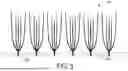
FIG. 3 is a schematic diagram illustrating an eyelash cluster sheet, according to an example of the present disclosure. The eyelash cluster sheet 300 includes a structured assembly of multiple eyelash clusters 302A-302F and an adhesive substrate 304.
Each eyelash cluster 302A-302F consists of a group of eyelashes joined at a single root portion. The eyelashes may be pre-shaped using a vacuum negative-pressure die-forming process to produce a curved tip, giving the clusters a natural, fanned appearance. In some examples, the clusters 302A-302F are evenly spaced along the length of the adhesive substrate 304, which temporarily secures them during downstream assembly processes. The spacing between clusters may vary depending on the desired lash style and may range from 0.1 mm to 10 mm. In other examples, the clusters may be irregularly spaced along the adhesive substrate 304 to achieve a different aesthetic effect.
The adhesive substrate 304 functions as a support structure during assembly and may include two functional sides: a first side 306 that holds the curved tip portions of the eyelash clusters 302A-302F, and a second side 308 that may contain excess eyelash material, which is trimmed away during the finishing stage.
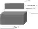
FIG. 4 is a schematic diagram illustrating a semi-finished product, according to an example of the present disclosure. As shown, the semi-finished product 400 includes a plurality of eyelash clusters 402A-402F, an adhesive substrate 404, and an auxiliary substrate 406. The eyelash clusters 402A-402F are arranged in a predetermined pattern along the adhesive substrate 404.
In this example, an eyelash cluster sheet, which includes eyelash clusters 402A-402F and the adhesive substrate 404, is positioned over the auxiliary substrate 406. A bonding process is then applied to secure the root portions of the eyelash clusters to the auxiliary substrate 406. The bonding may be performed using ultrasonic welding, thermal bonding, adhesive attachment, mechanical crimping, laser bonding, or combinations thereof. In embodiments using ultrasonic welding, a welding head may be pressed downward until it contacts the end portions of the eyelash clusters, after which ultrasonic energy and controlled pressure generate localized heat through high-frequency mechanical vibrations to fuse the root ends to the auxiliary substrate 406. Other bonding techniques may be applied in an analogous manner to form a stable attachment.
The auxiliary substrate 406 may be fabricated by a variety of methods depending on the desired material properties and shape. In some examples, the auxiliary substrate 406 is formed by laser cutting, where an auxiliary substrate raw material is placed on a positioning table and cut using a high-energy laser beam according to a preset cutting path. In some examples, the auxiliary substrate 406 is created through a 3D printing film-forming process, in which a digital three-dimensional model of the desired film is generated and sliced into multiple layers. A high-temperature-resistant release film may be preset on the working table of a 3D printer, and the printer deposits material layer by layer to form the auxiliary substrate. In other examples, the auxiliary substrate 406 may also be produced using film-forming techniques such as drawing molding, extrusion, or film blowing.
The auxiliary substrate 406 may take on various shapes, including strips, blocks, flakes, or clusters, depending on the design requirements of the eyelash product. The auxiliary substrate 406 may have a thickness ranging from 0.001 mm to 1 mm and a width ranging from 0.1 mm to 100 mm, depending on application requirements. In some examples, the auxiliary substrate may be made from polyester or other materials selected for durability, flexibility, and compatibility with the chosen bonding method. In some examples, the auxiliary substrate may be translucent or transparent, which helps to reduce visual visibility when applied, thereby enhancing the natural appearance of the lash line.
FIG. 5 is a schematic structural diagram of an artificial eyelash product, according to an example of the present disclosure. As depicted, the artificial eyelash product 500 includes a plurality of root portions 502 bonded to an auxiliary substrate 504. This configuration may be achieved through ultrasonic welding, thermal bonding, laser bonding, adhesive attachment, mechanical crimping, or combinations thereof, as described above, which securely affix the root portions of the eyelash clusters to the auxiliary substrate 504.
After the bonding process is complete, excess material, including any residual temporary substrate or misaligned lash fibers, is trimmed to yield the final artificial eyelash product. The resulting base structure formed by the auxiliary substrate 504 may exhibit smooth contours and a lightweight profile, which enhances both the aesthetic appeal and the wearing comfort of the product. Additionally, the soft and clean base improves compatibility with various application methods.
Using controlled bonding and precision trimming offers several substantial advantages. These benefits include providing a clean and uniform root region, enhancing user comfort, and improving overall product durability and longevity. In addition, the selected bonding method may decrease the likelihood of lash shedding or root detachment over time.
The finished artificial eyelash product 500 is lightweight and flexible, making it highly suitable for both professional eyelash-grafting applications and self-wear by individual consumers. Its refined construction ensures that it adheres comfortably to the skin or natural lash line, maintaining a natural look and feel throughout extended use. Furthermore, the product's structural integrity allows for multiple wears without deformation or loss of lash orientation.
FIG. 6 is a schematic structural diagram illustrating an example configuration of an artificial eyelash product 600 composed of two eyelash cluster sheets arranged in a layered and interlaced fashion, according to an embodiment of the present disclosure. This figure highlights an assembly strategy in which multiple eyelash cluster sheets are combined to enhance the volume, texture, and dimensionality of the final eyelash product.
In the illustrated example, two eyelash cluster sheets are used to construct the artificial eyelash product 600. The root portions of the cluster sheets are labeled as 602A and 602B, and the tip portions as 606A and 606B. In this example, the root portions 602A and 602B are placed adjacent to each other without overlapping, which helps to maintain a flat and low-profile base. This configuration minimizes bulk at the lash line, enhancing wearer comfort and simplifying application, particularly for self-wear or professional grafting. In another example (not shown in FIG. 6), the root portions of two or more eyelash cluster sheets may be intentionally overlapped to create a thicker and denser base appearance, which can enhance the perceived volume and intensity of the lash line for more dramatic styling preferences.
The tip portions of the eyelash cluster sheets, 606A and 606B, extend outwardly and are arranged in a crossed or interwoven pattern. In some examples, the two eyelash cluster sheets may be evenly crossed over, with the tips symmetrically layered to produce a balanced and uniform appearance. In other examples, the sheets may be unevenly crossed over, where the tips are offset or asymmetrically interlaced to create a more textured, wispy, or irregular effect. This overlapping of the lash tips creates a layered, three-dimensional appearance, giving the lashes enhanced volume and visual depth. The crossed tip arrangement contributes to a more natural look by mimicking the organic variation and complexity of real human eyelashes. Depending on the design intent, the crossing pattern may vary in angle, spacing, density, or direction, enabling the creation of diverse aesthetic styles such as soft and natural, bold and dramatic, or winged cat-eye effects.
The assembly process begins by affixing each eyelash cluster sheet to a secondary substrate to ensure stable positioning during bonding. The root portions 602A and 602B are then precisely aligned and bonded onto an auxiliary film 604. The bonding may be performed using ultrasonic welding, thermal bonding, adhesive attachment, mechanical crimping, laser bonding, or combinations thereof, depending on the selected manufacturing method. The auxiliary film serves as a flexible base layer for supporting the eyelash clusters and forming the lower structure of the artificial eyelash product. The bonding process securely joins the roots to the film, providing enhanced stability, consistency, and long-term durability.
After the bonding step, excess material, including portions of the temporary substrate and any misaligned lash fibers, may be trimmed away to form the clean edges and contours of the final product. The resulting artificial eyelash product 600 features a smooth and lightweight base formed by the auxiliary film 604, with lashes arranged in a visually rich and voluminous formation due to the crossover of the tip portions.
Although FIG. 6 illustrates only two eyelash cluster sheets, this configuration is merely exemplary. In other examples, multiple eyelash cluster sheets may be combined to form the artificial eyelash product. Each cluster sheet may feature a distinct eyelash pattern, where the term “eyelash pattern” refers to the specific arrangement and characteristics of individual eyelashes within a cluster sheet, including parameters such as eyelash length, curl curvature, spacing, thickness, and orientation. In some examples, a first eyelash cluster sheet having a first eyelash pattern may be paired with a second eyelash cluster sheet having a second, different eyelash pattern to achieve a customized design. For instance, shorter inner lashes on one sheet may be combined with longer outer lashes on another sheet to produce a graduated winged effect. In another example, eyelash cluster sheets with alternating curl types or varying densities may be layered to enhance depth, volume, and dimensional texture, resulting in a more natural or dramatic look depending on the desired aesthetic.
This method of combining multiple eyelash cluster sheets on a lightweight base enables manufacturers to create richly styled lashes while maintaining comfort, flexibility, and production efficiency. The modular design also simplifies the integration of varied lash styles, allowing mass customization with minimal changes to the core assembly process.
FIG. 7 is a schematic structural diagram of an ultrasonic welding machine according to an example of the present disclosure. The ultrasonic welding machine 700 includes a welding head 702, a holding tool 704, and a platform 706. The welding head 702 is the primary active component, responsible for generating ultrasonic vibrations. During operation, it is driven downward until it contacts the end portions of the eyelash clusters, which have been pre-aligned into an eyelash cluster sheet using adhesive substrate. This eyelash cluster sheet is then positioned on an auxiliary film for welding. The welding head 702 delivers ultrasonic energy while simultaneously applying controlled downward pressure. This combination of pressure and high-frequency vibrations generates localized heat at the interface between the eyelash roots and the auxiliary film, causing the materials to fuse and form a unified product.
The holding tool 704 is designed to securely position and stabilize the eyelash cluster sheet and the auxiliary film during the welding process. It may include customized slots, channels, or molds corresponding to the dimensions of the eyelash cluster sheet and auxiliary film to ensure consistent placement and alignment.
The platform 706 serves as the base surface. It provides structural support and may incorporate adjustable features such as height control, vibration dampening, or thermal resistance depending on production requirements. In some examples, the platform 606 may be integrated with a vacuum suction mechanism to assist in fixing lightweight materials such as the eyelash cluster sheet and/or the auxiliary film in place during welding.
In operation, a user first positions the auxiliary film and the eyelash clusters in the holding tool 704, which rests on the platform 706. The ultrasonic welding head 702 is then brought down into contact with the root areas of the eyelash clusters. Upon activation, ultrasonic vibrations are transmitted through the welding head, generating localized heat and bonding the materials. After the welding cycle is complete, the assembly is released, and the semi-finished eyelash product can proceed to the trimming and finishing stages.
FIG. 8 is a schematic diagram illustrating an artificial eyelash kit 800, according to an embodiment of the present disclosure. The eyelash kit 800 includes an auxiliary substrate 802 and a plurality of eyelash clusters 804 coupled to the auxiliary substrate 802. The auxiliary substrate 802 is configured for attachment to an eye region of a user, and may be formed as a strip, sheet, or band capable of supporting multiple eyelash clusters. Each eyelash cluster 804 includes a root region affixed to the auxiliary substrate 802 and a plurality of eyelashes extending from the root region, thereby enabling the eyelashes to be positioned and secured along a user's natural lash line. The eyelash kit 800 further includes an applicator tool 806 configured to position or attach one or more of the eyelash clusters 804 to the eye region of the user. As depicted in FIG. 8, the applicator tool 806 may be selected from various tool configurations depending on the installation technique, desired styling effect, or attachment mechanism used by the user.
In some examples, the applicator tool 806 comprises a cluster transfer tool 806A, as illustrated in FIG. 8. The cluster transfer tool 806A may include tweezer-type arms or precision gripping features configured to lift either the entire artificial eyelash product or individual eyelash clusters 804 from the auxiliary substrate 802 and transfer them to a desired location along the user's eyelid or natural lash line. The cluster transfer tool 806A provides enhanced control and precision for applications such as professional lash grafting, self-wear installation, or detailed placement and adjustment of one or more eyelash clusters.
In some examples, the applicator tool 806 comprises an adhesive applicator 806B. The adhesive applicator 806B may include a pen-shaped or brush-tipped dispensing structure configured to deliver an adhesive, bonding agent, or other attachment medium to either the root region of an eyelash cluster 804 or directly to the user's eye region. Such an applicator may support both self-wear lash attachment and professional installation methods requiring controlled application of adhesive materials.
In some examples, the auxiliary substrate 802 may include a magnetic component, and the applicator tool may comprise a magnetic applicator 806C configured to magnetically secure the eyelash clusters 804 to the eye region of the user. The magnetic applicator 806C may include a magnetic head or contact surface that interacts with magnetic elements embedded within the auxiliary substrate 802 or the eyelash clusters 804, thereby enabling non-adhesive attachment and simplified alignment.
In some examples, the applicator tool 806 comprises a positioning tool 806D configured to align the eyelash clusters 804 against the eye region of the user. The positioning tool 806D may include a curved or contoured surface shaped to correspond to typical eyelid curvature, enabling the user to press or guide the eyelash clusters 804 into their correct position. The positioning tool 806D may assist in achieving consistent orientation, improved symmetry, or a more natural visual effect.
Although four examples of applicator tools—806A, 806B, 806C, and 806D—are illustrated in FIG. 8, the eyelash kit 800 is not limited to the particular tool types shown. Additional or alternative applicators, including those providing multifunctional capabilities or adjustable features, may also be incorporated without departing from the scope of the present disclosure.
In one example, the present disclosure provides an artificial eyelash product, including: an auxiliary substrate configured for attachment to an eye region of a user; and a plurality of eyelash clusters coupled to the auxiliary substrate, each eyelash cluster being capable of being attached to the eye region of the user, wherein at least one eyelash cluster includes: a root region affixed to the auxiliary substrate; and a plurality of eyelashes extending from the root region.
In some examples, the root region includes a bonded portion formed by at least one of: ultrasonic welding, thermal melting, laser bonding, mechanical crimping, chemical bonding, or adhesive attachment.
In some examples, the auxiliary substrate includes a supporting structure, the supporting structure includes a strip, a sheet, a block, a flake, a film, or a band.
In some examples, the supporting structure includes polyester, polyurethane, nylon, cotton, silk, cellulose-based fiber, a thermoplastic elastomer, a magnetically responsive material, or a magnetic component.
In some examples, the plurality of eyelash clusters is provided on an eyelash cluster sheet affixed to the auxiliary substrate.
In some examples, the plurality of eyelashes of the eyelash cluster includes a curved tip portion formed by a vacuum negative-pressure shaping process.
In some examples, the auxiliary substrate has a colored, translucent, or transparent appearance.
In some examples, at least two of the plurality of eyelash clusters are interlaced, overlapped, or layered.
In some examples, the plurality of eyelash clusters includes a pigment coating or waterproofing coating.
In one example, the present disclosure provides a method for manufacturing an artificial eyelash product, including: arranging a plurality of eyelashes into a root region; bonding the plurality of eyelashes at the root region to form an eyelash cluster; and coupling a plurality of eyelash clusters to an auxiliary substrate configured for attachment to an eye region of a user, wherein each eyelash cluster of the plurality of eyelash clusters is capable of being attached to the eye region of the user.
In some examples, the bonding includes ultrasonic welding, thermal melting, laser bonding, mechanical crimping, chemical bonding, or adhesive attachment of the root region.
In some examples, coupling the plurality of eyelash clusters to the auxiliary substrate further includes: attaching the plurality of eyelash clusters to an eyelash cluster sheet;
and affixing the eyelash cluster sheet to the auxiliary substrate.
In some examples, the method further including: shaping a tip portion of the eyelash cluster into a curved configuration using a vacuum negative-pressure shaping process.
In some examples, coupling the plurality of eyelash clusters to the auxiliary substrate further includes: positioning at least two of the plurality of eyelash clusters in an interlaced, overlapped, or layered arrangement.
In some examples, the method further including: applying a pigment coating or a waterproofing coating to the plurality of eyelash clusters.
In one example, the present disclosure provides an artificial eyelash kit, including: an auxiliary substrate configured for attachment to an eye region of a user; and a plurality of eyelash clusters coupled to the auxiliary substrate, each eyelash cluster being capable of being attached to the eye region of the user, wherein at least one eyelash cluster includes a root region affixed to the auxiliary substrate and a plurality of eyelashes extending from the root region; and an applicator tool configured to position or attach the eyelash cluster to the eye region of the user.
In some examples, the applicator tool includes a cluster transfer tool configured to transfer the eyelash clusters from the auxiliary substrate to the eye region of the user.
In some examples, the applicator tool includes an adhesive applicator configured to attach the eyelash cluster to the eye region of the user.
In some examples, the auxiliary substrate includes a magnetic component, wherein the applicator tool includes a magnetic applicator configured to secure the eyelash cluster to the eye region of the user.
In some examples, the applicator tool includes a positioning tool configured to align the eyelash cluster against the eye region of the user.
The specific structure of the artificial eyelash product may refer to the foregoing embodiments. The artificial eyelash product adopts the technical solutions described in the foregoing embodiments and therefore achieves at least the technical effects associated with those solutions. Accordingly, the details of such structures are not repeated herein.
The above are only some embodiments of the present disclosure, and neither the words nor the drawings can limit the protection scope of the present disclosure. Any equivalent structural transformation made by using the contents of the specification and the drawings of the present disclosure under the overall concept of the present disclosure, or directly/indirectly applied in other related technical fields are included in the protection scope of the present disclosure.
Claims
What is claimed is:1. An artificial eyelash product, comprising:
an auxiliary substrate configured for attachment to an eye region of a user; and
a plurality of eyelash clusters coupled to the auxiliary substrate, each eyelash cluster being capable of being attached to the eye region of the user,
wherein at least one eyelash cluster comprises:
a root region affixed to the auxiliary substrate; and
a plurality of eyelashes extending from the root region.
2. The artificial eyelash product of claim 1, wherein the root region comprises a bonded portion formed by at least one of: ultrasonic welding, thermal melting, laser bonding, mechanical crimping, chemical bonding, or adhesive attachment.
3. The artificial eyelash product of claim 1, wherein the auxiliary substrate comprises a supporting structure, the supporting structure comprises a strip, a sheet, a block, a flake, a film, or a band.
4. The artificial eyelash product of claim 3, wherein the supporting structure comprises polyester, polyurethane, nylon, cotton, silk, cellulose-based fiber, a thermoplastic elastomer, a magnetically responsive material, or a magnetic component.
5. The artificial eyelash product of claim 1, wherein the plurality of eyelash clusters is provided on an eyelash cluster sheet affixed to the auxiliary substrate.
6. The artificial eyelash product of claim 1, wherein the plurality of eyelashes of the eyelash cluster includes a curved tip portion formed by a vacuum negative-pressure shaping process.
7. The artificial eyelash product of claim 1, wherein the auxiliary substrate has a colored, translucent, or transparent appearance.
8. The artificial eyelash product of claim 1, wherein at least two of the plurality of eyelash clusters are interlaced, overlapped, or layered.
9. The artificial eyelash product of claim 1, wherein the plurality of eyelash clusters comprises a pigment coating or waterproofing coating.
10. A method for manufacturing an artificial eyelash product, comprising:
arranging a plurality of eyelashes into a root region;
bonding the plurality of eyelashes at the root region to form an eyelash cluster; and
coupling a plurality of eyelash clusters to an auxiliary substrate configured for attachment to an eye region of a user, wherein each eyelash cluster of the plurality of eyelash clusters is capable of being attached to the eye region of the user.
11. The method of claim 10, wherein the bonding comprises ultrasonic welding, thermal melting, laser bonding, mechanical crimping, chemical bonding, or adhesive attachment of the root region.
12. The method of claim 10, wherein coupling the plurality of eyelash clusters to the auxiliary substrate further comprises:
attaching the plurality of eyelash clusters to an eyelash cluster sheet; and
affixing the eyelash cluster sheet to the auxiliary substrate.
13. The method of claim 10, further comprising:
shaping a tip portion of the eyelash cluster into a curved configuration using a vacuum negative-pressure shaping process.
14. The method of claim 10, wherein coupling the plurality of eyelash clusters to the auxiliary substrate further comprises:
positioning at least two of the plurality of eyelash clusters in an interlaced, overlapped, or layered arrangement.
15. The method of claim 10, further comprising:
applying a pigment coating or a waterproofing coating to the plurality of eyelash clusters.
16. An artificial eyelash kit, comprising:
an auxiliary substrate configured for attachment to an eye region of a user; and
a plurality of eyelash clusters coupled to the auxiliary substrate, each eyelash cluster being capable of being attached to the eye region of the user, wherein at least one eyelash cluster comprises a root region affixed to the auxiliary substrate and a plurality of eyelashes extending from the root region; and
an applicator tool configured to position or attach the eyelash cluster to the eye region of the user.
17. The artificial eyelash kit of claim 16, wherein the applicator tool comprises a cluster transfer tool configured to transfer the eyelash clusters from the auxiliary substrate to the eye region of the user.
18. The artificial eyelash kit of claim 16, wherein the applicator tool comprises an adhesive applicator configured to attach the eyelash cluster to the eye region of the user.
19. The artificial eyelash kit of claim 16, wherein the auxiliary substrate comprises a magnetic component, wherein the applicator tool comprises a magnetic applicator configured to secure the eyelash cluster to the eye region of the user.
20. The artificial eyelash kit of claim 16, wherein the applicator tool comprises a positioning tool configured to align the eyelash cluster against the eye region of the user.
Images & Drawings included:


Sources:
- United States Patent and Trademark Office - verify current appl. status at the USPTO↗
Recent applications in this class:
- » 20260114530 2026-04-30
SYSTEMS FOR GENERATING CUSTOMIZED EYELASH EXTENSIONS - » 20260083199 2026-03-26
SYSTEM FOR APPLYING ARTIFICIAL EYELASHES - » 20260076430 2026-03-19
ARTIFICIAL EYELASH EXTENSIONS AND METHODS OF MANUFACTURING SAME - » 20260060353 2026-03-05
SELF-ADHESIVE FALSE EYELASHES AND PREPARATION METHOD THEREOF - » 20260060352 2026-03-05
CUTTING APPARATUS FOR FALSE EYELASHES - » 20260060351 2026-03-05
APPLICATOR FOR ARTIFICIAL EYELASH EXTENSION SYSTEMS - » 20260047633 2026-02-19
Eyelash Isolation Hook and Spreader Tool - » 20260041183 2026-02-12
ADHESIVE FOR COSMETIC ARTICLE AND METHOD OF FORMING - » 20260020631 2026-01-22
APPLICATOR SET FOR ARTIFICIAL EYELASH EXTENSION SYSTEMS AND PACKAGE ACCOMMODATING THE SAME - » 20260013588 2026-01-15
READY-TO-USE EYELASH EXTENSIONS