TRAY
US20260116612A1
2026-04-30
19/244,319
2025-06-20
Smart Summary: The tray has a flat base and is surrounded by raised edges. It features special parts on the bottom that create friction to prevent slipping. The edges are taller than the supports that hold the tray up. The friction parts are even lower than the supports. The design ensures that the height difference between certain parts of the tray is just right for stability. 🚀 TL;DR
Abstract:
A tray includes a floor member, a plurality of first edge members, a plurality of second edge members and a plurality of support members. The floor member includes a plurality of friction members. The plurality of first edge members and the plurality of second edge members each has a first height. The plurality of support members each has a second height lower than the first height. The plurality of friction members each has a third height lower than the second height. A distance between a plane making contact with a lowermost end of each of the plurality of second edge members and a lowermost end of a center of the floor member is between 12 and 23 percents, inclusive, of the first height.
Inventors:
- Bo Bae SIM 3 🇰🇷 Yongin-si, South Korea
- Min Yeob KANG 3 🇰🇷 Yongin-si, South Korea
- NAMPYO HONG 2 🇰🇷 YONGIN-SI, South Korea
- SUNGKI SONG 1 🇰🇷 Yongin-si, South Korea
Applicant:
Interested in similar patents?
Get notified when new applications in this technology area are published.
Classification:
B65D1/34 » CPC main
Containers having bodies formed in one piece, e.g. by casting metallic material, by moulding plastics, by blowing vitreous material, by throwing ceramic material, by moulding pulped fibrous material, by deep-drawing operations performed on sheet material Trays or like shallow containers
Description
CROSS-REFERENCE TO RELATED APPLICATIONS
This application claims priority to and benefits of Korean Patent Application No. 10-2024-0149692 under 35 U.S.C § 119, filed on October 29, 2024, in the Korean Intellectual Property Office, the contents of which are incorporated by reference herein in its entirety.
BACKGROUND
1. Technical Field
The disclosure relates to a tray for carrying or storing a display panel or an electronic part, more particularly, to a technique of stacking several trays, each loaded with a display panel or an electronic part.
2. Description of the Related Art
A tray is used to carry or store a product at a site of manufacturing a display panel or an electronic part. A conventional tray may have an inner partition so that only a product having a suitable size and shape can be loaded.
When multiple conventional trays are stacked, the upper tray experiences a load, causing it to bend. As it bends, the upper conventional tray may come into contact with the display panel in the lower conventional tray, potentially leading to defects in the display panel.
SUMMARY
An object of the disclosure is to provide a tray having a dome structure and a support member configured to disperse a load to effectively prevent bending of the tray.
Another object of the disclosure is to provide a tray with improved carrying efficiency by stacking several trays to load a large amount of display panels or electronic parts.
According to an aspect of the present disclosure, a tray may include a floor member, a plurality of first edge members, a plurality of second edge members and a plurality of support members. The floor member may have a selectable curvature. The plurality of first edge members may be disposed on a first outer side of the floor member and extend lengthwise in a first direction. The plurality of second edge members may be disposed on a second outer side of the floor member different from the first outer side of the floor member and extend lengthwise in a second direction intersecting with the first direction. The plurality of support members may be disposed adjacent to the plurality of first edge members and the plurality of second edge members. The floor member may include a plurality of friction members protruding in a third direction perpendicular to the first direction and the second direction. The plurality of first edge members and the plurality of second edge members may each have a first height. The plurality of support members may each have a second height, lower than the first height The plurality of friction members may each have a third height, lower than the second height.
In an embodiment of the disclosure a distance between a plane making contact with a lowermost end of each of the plurality of second edge members and a lower end of a center of the floor member may be between 12 and 23 percents, inclusive, of the first height.
In an embodiment of the disclosure, the height different may be between 14 and 16 percents, inclusive, of the first height.
In an embodiment of the disclosure, the plurality of first edge members may include a first sub-edge member and a second sub-edge member, and the plurality of second edge members may include a third sub-edge member and a fourth sub-edge member. The plurality of support members may include a first support member, a second support member, a third support member and a fourth support member. The first support member may be spaced apart by a first spacing from an outermost side of the first sub-edge member and by a second spacing from an outermost side of the third sub-edge member. The second support member may be spaced apart by the first spacing from the outermost side of the first sub-edge member and by the second spacing from an outermost side of the fourth sub-edge member. The third support member may be spaced apart by the first spacing from an outermost side of the second sub-edge member and by the second spacing from the outermost side of the third sub-edge member. The fourth support member may be spaced apart by the first spacing from the outermost side of the second sub-edge member and by the second spacing from the outermost side of the fourth sub-edge member.
In an embodiment, the first spacing may be between 13 and 15 percents, inclusive, of a length of the third sub-edge member measured in the second direction. The second spacing may be between 8 and 10 percents, inclusive, of a length of the first sub-edge member measured in the first direction.
In an embodiment, the plurality of support members may further include a fifth support member and a sixth support member. The fifth support member may be spaced apart by the first spacing from the outermost side of the first sub-edge member, and the sixth support member may be spaced apart by the first spacing from the outermost side of the second sub-edge member.
In an embodiment, the first support member and the second support member may be symmetrically disposed with respect to the fifth support member. The third support member and the fourth support member may be symmetrically disposed with respect to the sixth support member.
In an embodiment of the disclosure, the second height may be between 22 and 45 percents, inclusive, of the first height.
In an embodiment of the disclosure, the first height may be between 18 mm and 22 mm, inclusive, and the second height may be between 5 mm and 7 mm, inclusive.
In an embodiment of the disclosure, the plurality of friction members may each have a hexagonal shape when viewed in a plan view.
In an embodiment of the disclosure, the floor member, the plurality of first edge members and the plurality of second edge members may be integrally connected with each other and may be formed of plastic.
In an embodiment of the disclosure, the plurality of support members may not overlap the plurality of friction members when viewed in a plan view.
According to an aspect of the present disclosure, a tray may include a floor member, a first edge member, a second edge member and a support member. The floor member may have a selectable curvature. The first edge member may be disposed on a first outer side of the floor member, extend lengthwise in a first direction and have a first height. The second edge member may be disposed on a second outer side of the floor member different from the first outer side of the floor member, extend lengthwise in a second direction intersecting with the first direction and have the first height. The support member may be provided to protrude in a direction perpendicular to the first direction and the second direction and have a second height, lower than the first height. The floor member may include a first portion, a second portion and a third portion. The first portion may be adjacent to a region of intersection of the first edge member and the second edge member and have a third height, lower than the second height. The second portion may be adjacent to the first portion and have a fourth height, lower than the third height, The third portion may be adjacent to the second portion and have a fifth height, lower than the fourth height,
In an embodiment of the disclosure, the second height may be between 22 and 45 percents, inclusive, of the first height.
In an embodiment of the disclosure, the first height may be between 18 mm and 22 mm, inclusive, and the second height may be between 5 mm and 7 mm, inclusive.
In an embodiment of the disclosure, the support member may be spaced apart by a first spacing from an outermost end of the first edge member and by a second spacing from an outermost end of the second edge member.
In an embodiment of the disclosure, the first spacing may be between 13 and 15 percents, inclusive, of a length of the second edge member measured in the second direction. The second spacing may be between 8 and 10 percents, inclusive, of a length of the first edge member measured in the first direction.
In an embodiment of the disclosure, a distance between a plane making contact with lowermost ends of the first edge member and the second edge member and a lowermost end of a center of the floor member may be between 12 and 23 percents, inclusive, of the first height.
In an embodiment of the disclosure, the height difference may be between 14 and 16 percents, inclusive, of the first height.
In an embodiment of the disclosure, the third portion may have a shape of surrounding the support member when viewed in a plan view. The support member may not overlap the first portion when viewed in the plan view.
According to an embodiment of the disclosure, it becomes possible to provide a tray configured to disperse a load to effectively prevent bending of the tray by having a dome structure and a support member.
According to an embodiment of the disclosure, it becomes possible to provide a tray with improved carrying efficiency by stacking several trays to load a large amount of display panels or electronic parts.
BRIEF DESCRIPTION OF THE DRAWINGS
These and/or other features will become apparent and more readily appreciated from the following description of the embodiments, taken in conjunction with the accompanying drawings in which:
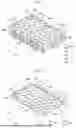
FIG. 1 is an exemplary perspective view of stacking of several trays according to an embodiment of the present disclosure;
FIG. 2 is an exemplary perspective view of one of the trays in FIG. 1 according to an embodiment of the present disclosure;
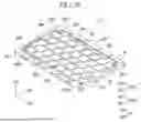
FIG. 3 is an exemplary plan view of the tray in FIG. 2 according to an embodiment of the present disclosure;
FIG. 4A is an exemplary illustration of a cross-section of a tray taken along the line I-I’ shown in FIG. 2 according to an embodiment of the present disclosure;
FIG. 4B is an exemplary illustration of a cross-section of a tray taken along the line II-II’ shown in FIG. 2 according to an embodiment of the present disclosure;
FIG. 5 is an exemplary illustration of a cross-section of a stack of several trays in FIG. 4A according to an embodiment of the present disclosure;
FIG. 6 is an exemplary illustration of a display panel disposed on a tray according to an embodiment of the present disclosure;
FIGS. 7A through 7C are exemplary simulated illustrations according to conditions of a load on a center of the tray;
FIG. 8 is an exemplary perspective view of a tray according to another embodiment of the present disclosure;
FIG. 9 is an exemplary perspective view of a tray according to yet another embodiment of the present disclosure; and
FIG. 10 is an exemplary perspective view of a tray according to even yet another embodiment of the present disclosure.
DETAILED DESCRIPTION
References will now be made in detail to certain embodiments, of which examples are illustrated in the accompanying drawings, where like reference numerals refer to like elements throughout. The embodiments may have a variety of forms and permutations, but the present disclosure shall by no means be construed as being limited to the described embodiments. Rather, the present disclosure shall be construed to encompass all forms, permutations, equivalents and substitutes covered by the technical ideas and scope of the present disclosure. Accordingly, the embodiments are merely described below, by referring to the figures, to explain features of the present disclosure.
Like or identical reference numerals refer to like or identical elements. Moreover, in the accompanying drawings, the thicknesses, ratios, and dimensions of the elements may not be to exact scale and may have been exaggerated for the benefit of effective explanation of the technical features associated with these elements. As such, the present disclosure shall not be restricted to the thicknesses, ratios, dimensions, etc. illustrated in the drawings. In addition, elements described to be related with the term “and/or” include all of one or more possible combinations.
An expression such as “comprising” or “including” is intended to designate a characteristic, a number, a step, an operation, an element, a part or combinations thereof, and shall not be construed to preclude any possibility of presence or addition of one or more other characteristics, numbers, steps, operations, elements, parts or combinations thereof.
Unless otherwise defined, all terms, including technical terms and scientific terms, used herein have the same meaning as how they are generally understood by those of ordinary skill in the art to which the present disclosure pertains. Any term that is defined in a general dictionary shall be construed to have the same meaning in the context of the relevant art, and, unless otherwise defined explicitly, shall not be interpreted to have an idealistic or excessively formalistic meaning.
FIG. 1 is an exemplary perspective view of a stack of several trays TY according to an embodiment of the disclosure. FIG. 2 is an exemplary perspective view of one of the trays TY in FIG. 1.
A first direction DR1, a second direction DR2, and a third direction DR3 are shown. According to an embodiment of the disclosure, a display panel or an electronic part may be disposed on a plane defined by a straight line extending in the first direction DR1 and a straight line extending in the second direction DR2. The third direction DR3 is perpendicular to the first direction DR1 and the second direction DR2. However, the first through the third directions are merely set as an example, and the directions may be modified as necessary.
A tray TY may be a device for carrying a display panel or an electronic part. For example, an electronic part disposed on the tray TY may be a part to be mounted in an at least one electronic device of a monitor, a television, a smartphone, a navigation, a terminal to be mounted in a vehicle, and a tablet PC. Several trays TY may be stacked. Therefore, a tray TY may have high carrying efficiency by loading a large number of display panels or electronic parts.
A tray TY may include or may be formed of a plastic material. For example, the plastic material may include, polyethylene (PE), polypropylene (PP), polystyrene (PS), polyethylene terephthalate (PET), polyamides (PA), polyester (PES), polyvinyl chloride (PVC), polyurethanes (PU), polycarbonate (PC), or polyvinylidene chloride (PVDC). However, the disclosure is not limited to the above examples, and a material included in a tray TY may be modified as necessary.
Referring to FIGS. 1 and 2, the tray TY may include a floor member FL, a plurality of first edge members EDG1, a plurality of second edge members EDG2, and a plurality of support members SPM1 through SPM6.
The floor member FL may have a selectable curvature. A description thereof will be made with reference to FIG. 4.
The plurality of first edge members EDG1 may be each disposed on a first outer side of the floor member FL and extend lengthwise in a first direction DR1. Here, the plurality of first edge members’ disposition on a first outer side may mean that a side of each of the plurality of first edge members EDG1 makes contact with a side of the floor member FL. For example, the arrangement of multiple first edge members EDGE1 on the first outer side may indicate that one side of each first edge member EDG1 contacts a side of the floor member FL.
The plurality of second edge members EDG2 may be each disposed on a second outer side of the floor member FL different from the first outer side and extend lengthwise in a second direction DR2. Here, the plurality of second edge members’ disposition on a second outer side may mean that a side of each of the plurality of edge members EDG2 makes contact with another side of the floor member FL. For example, the arrangement of multiple second edge members EDGE2 on the second outer side may indicate that one side of each second edge member EDG2 contacts another side of the floor member FL.
The plurality of first edge members EDG1 and the plurality of second edge members EDG2 may have a shape of surrounding the floor member FL. The plurality of first edge members EDG1 and the plurality of second edge members EDG2 may surround a side of the floor member FL (e.g., four sides of the floor member FL), but the disclosure is not limited to the example. For example, the plurality of first edge members EDG1 and the plurality of second edge members EDG2 may be disposed on the floor member FL.
The plurality of first edge members EDG1 may include a first sub edge SEG1 (i.e., a first sub-edge member) and a second sub edge SEG2 (i.e., a second sub-edge member).
According to an embodiment of the disclosure, the first sub edge SEG1 and the second sub edge SEG2 may compose a long side of the first outer side of the tray TY. However, the disclosure is not limited to the embodiment.
According to an embodiment of the disclosure, the first sub edge SEG1 and the second sub edge SEG2 may include a plurality of grooves HM and a plurality of air slots ARS. A shape of the plurality of grooves HM may be a shape having an outer wall of the first sub edge SEG1 and the second sub edge SEG2 partially curved. For example, the plurality of grooves HM may be formed to have a semicircular shape. Several trays TY may be easily stacked with the plurality of grooves HM.
Each of the plurality of air slots ARS may have a shape of penetrating the first and second sub edges SEG1 and SEG2 from an inner side to an outer side. Air may be introduced or discharged through the plurality of air slots ARS. Accordingly, an inner pressure of a display panel or an electronic part to be loaded in a tray TY may be constantly maintained.
The plurality of second edge members EDG2 may include a third sub edge SEG3 (i.e., a third sub-edge member) and a fourth sub edge SEG4 (i.e., a fourth sub-edge member).
According to an embodiment of the disclosure, the third sub edge SEG3 and the fourth sub edge SEG4 may compose a short side of the second outer side of the tray TY. However, the disclosure is not limited to the embodiment.
According to an embodiment of the disclosure, the third sub edge SEG3 and the fourth sub edge SEG4 may include a plurality of grooves HM. A shape of the plurality of grooves HM may have a shape having an outer wall of the third sub edge SEG3 and the fourth sub edge SEG4 partially curved. For example, the plurality of grooves HM may have a semicircular shape. Several trays TY may be easily stacked with the plurality of grooves HM.
The floor member FL may include a plurality of friction members NSM and a middle member MM disposed between the plurality of friction members NSM. In an embodiment, the middle member MM may have an upper surface. The plurality of friction members NSM may protrude from the middle member in the third direction DR3. For example, each of the friction members NSM may protrude from the upper surface of the middle member MM. The plurality of friction members NSM may be periodically disposed. In other words, the plurality of friction members NSM may have a same shape and disposed to be spaced apart by a selectable distance from each other. Each of the plurality of friction members NSM is exemplarily described to have a hexagonal shape. However, the disclosure is not limited to the example, and the plurality of friction members NSM may each have a various shape, such as a rectangle, a rhombus, a pentagon, and a circle. In FIG. 8, each of the friction members NSM may have a shape of a rectangle or a rhombus.
The plurality of friction members NSM may be each referred as a first portion. The middle member MM may be referred as a second portion.
The plurality of support members SPM1 through SPM6 may protrude in the third direction DR3. In an embodiment, each of the support members SPM1 through SPM6 may protrudes from the upper surface of the middle member MM. A shape of each of the plurality of support members SPM1 through SPM6 is illustrated to have a cylindrical shape. However, the disclosure is not limited to the example, and in another embodiment, the shape may be freely modified. For example, a shape of each of the plurality of support members SPM1 through SPM6 may be a rectangular parallelepiped, a regular hexahedron, or a cone. An additional element may be added to the plurality of support members SPM1 through SPM6. For example, a buffer member ABM may be added to the plurality of support members SPM1 through SPM6. The embodiment is shown in FIG. 10. In an embodiment, the buffer member ABM may be disposed on an upper end of each of the plurality of support members SPM1 through SPM6.
A shape and a configuration of the plurality of support members SPM1 through SPM6 are not limited to the embodiment, and any structure of supporting a tray TY stacked above may suffice. The middle member MM may include a portion surrounding each of the plurality of support members SPM1 through SPM6 may be referred as a third portion PM.
A manufacturing method of a tray TY according to an embodiment may be simply described as follows. First, a liquid component is applied to an entire upper surface of a substrate to be manufactured and then dried. The liquid component may be, for example, an elastomer. Subsequently, a plurality of first edge members EDG1, a plurality of second edge members EDG2, a plurality of support members SPM1 through SPM6, a plurality of friction members NSM, and a middle member MM may be manufactured through a vacuum molding method. For example, the first and second edges EDGE1 and EDGE2, the support members SPM1 through SPM6, the friction members NSM, and the middle member MM may be integrally connected with each other.
FIG. 3 is an exemplary plan view of the tray in FIG. 2. A length of each of the first sub edge SEG1 and the second sub edge SEG2 measured in the first direction DR1 may be about 650 mm. A length of each of the third sub edge SEG3 and the fourth sub edge SEG4 measured in the second direction DR2 may be about 450 mm.
The plurality of support members SPM1 through SPM6 may include a first through a sixth support member SPM1 through SPM6. The first support member SPM1 may be disposed adjacent to a portion where the first sub edge SEG1 and the third sub edge SEG3 intersects. The first support member SPM1 may be disposed most left in the first direction DR1, and the fifth support member SPM5 and the second support member SPM2 may be successively disposed in the first direction DR1.
The first support member SPM1 may be spaced apart by a first spacing d1 from an outermost end (i.e., an outermost side) of the first sub edge SEG1 and by a second spacing d2 from an outermost end (i.e., an outermost side) of the third sub edge SEG3.
The second support member SPM2 may be spaced apart by the first spacing d1 from the outermost end of the first sub edge SEG1 and by the second spacing d2 from an outermost end (i.e., an outermost side) of the fourth sub edge SEG4.
In an embodiment of the disclosure, the first spacing d1 may be between 13 and 15 percents, inclusive, of a length of the third sub edge SEG3. In case that the first spacing d1 is less than 13 percents of the length of the third sub edge SEG3, the first support member SPM1 and the second support member SPM2 may not effectively support another tray TY disposed above. In case that the first spacing d1 is greater than 15 percents of the length of the third sub edge SEG3, the first support member SPM1 and the second support member SPM2 may be too close to a center of the floor member FL so that a space for placing a display panel or an electronic part may become small.
In an embodiment of the disclosure, the second spacing d2 may be between 8 and 10 percents, inclusive, of a length of the first sub edge SEG1. As described above, in case that the second spacing d2 is less than 8 percents of the length of the first sub edge SEG1, the first support member SPM1 and the second support member SPM2 may not effectively support another tray TY disposed above. In case that the second spacing d2 is greater than 10 percents of the length of the first sub edge SEG1, the first support member SPM1 and the second support member SPM2 may be too close to a center of the floor member FL so that a space for placing a display panel or an electronic part may become small.
In an embodiment of the disclosure, the first spacing d1 may be about between 58.5 mm and 67.5 mm, inclusive. The second spacing d2 may be about between 52 mm and 65 mm, inclusive. However, the disclosure is not limited to the example, and a measurement of the first spacing d1 and the second spacing d2 may be modified according to a size of a tray TY and a display panel to be loaded on a tray TY.
The third support member SPM3 may be disposed on a portion adjacent to a portion where the second sub edge SEG2 and the third sub edge SEG3 intersects. The third support member SPM3 may be disposed most left in the first direction DR1, and the sixth support member SPM6 and the fourth support member SPM4 may be successively disposed in the first direction DR1.
The third support member SPM3 may be spaced apart by the first spacing d1 from an outermost end (i.e., an outermost side) of the second sub edge SEG2 and by the second spacing d2 from the outermost end of the third sub edge SEG3.
The fourth support member SPM4 may be spaced apart by the first spacing d1 from the outermost end of the second sub edge SEG2 and by the second spacing d2 from an outermost end of the fourth sub edge SEG.4
The fifth support member SPM5 may be spaced apart by the first spacing d1 from the outermost end of the first sub edge SEG1. The first support member SPM1 and the second support member SPM2 may be symmetrically disposed with respect to the fifth support member SPM5. In an embodiment of the disclosure, the fifth support member SPM5 may be disposed to be spaced apart by about 325 mm from the outermost end of the third sub edge SEG3.
The sixth support member SPM6 may be spaced apart by the first spacing d1 from the outermost end of the second sub edge SEG2. The third support member SPM3 and the fourth support member SPM4 may be symmetrically disposed with respect to the sixth support member SPM6. The sixth support member SPM6 may be disposed to be spaced apart by about 325 mm from the outermost end of the third sub edge SEG3. Hereinafter, a description of the first spacing d1 and the second spacing d2 may be identical to the above description and therefore omitted.
A number of the plurality of support members SPM1 through SPM6 is illustrated, for example, to be 6. However, the disclosure is not limited to the example, and the number may be increased or decreased as necessary.
Referring to FIG. 3, the plurality of support members SPM1 through SPM6 and the plurality of friction members NSM may not overlap on a plane (i.e., when viewed in a plan view).
FIG. 4A is an exemplary illustration of a cross-section of a tray TY taken along the line I-I’ shown in FIG. 2. FIG. 4B is an exemplary illustration of a cross-section of a tray TY taken along the line II-II’ shown in FIG. 2.
In FIG. 4A, a plane making contact with a lowermost end of each of the third sub edge SEG3 and the fourth sub edge SEG4 is illustrated as a plane a-a’. According to an embodiment of the disclosure, a distance from the plane a-a’ to an upper portion of each of the third sub edge SEG3 and the fourth sub edge SEG4 may be a first height HE1. For example, the first height HE1 may be about 20 mm. However, the disclosure is not limited to the example, and the first height HE1 may be modified according to a size of a display panel or an electronic part to be loaded on the tray TY.
Referring to FIG. 4A, the first support member SPM1, the fifth support member SPM5, and the second support member SPM2 may each have a same height. For example, the first support member SPM1, the fifth support member SPM5, and the second support member SPM2 may each have a height of about 6 mm. However, the disclosure is not limited to the example, and a height of each of the first support member SPM1, the fifth support member SPM5, and the second support member SPM2 may be modified as necessary in another embodiment. A height of each of the plurality of support members SPM1 through SPM6 may be referred as a second height HE2.
Cross-sections of the third support member SPM3, the sixth support member SPM6 and the fourth support member SPM4 are not illustrated in the disclosure. However, according to an embodiment of the disclosure, a height and a shape of each of the third support member SPM3, the sixth support member SPM6, and the fourth support ember SPM4 may be substantially identical to the height and the shape of the first support member SPM1, the fifth support member SPM5, and the second support member SPM2.
Each of the plurality of friction members NSM may have a third height HE3 lower than the second height HE2 in the disclosure.
Referring to FIG. 4B, a distance FD between a plane making contact with a lowermost end of each of the third sub edge SEG3 and the fourth sub edge SEG4 and a lowermost end of a center of the floor member FL may be between 12 and 23 percents, inclusive, of the first height HE1. For example, the distance FD may be about 3 mm. However, the disclosure is not limited to the example, and the first height HE1 and the distance FD may be modified according to a display panel or an electronic part to be loaded on the tray TY.
In case that the distance FD is less than 12 percents of the first height HE1, the first support member SPM1 and the second support member SPM2 may not effectively support another tray TY disposed above. As described above, a height of each of the first support member SPM1 and the second support member SPM2 is lower than the first height HE1. Accordingly, the distance FD may be sufficient to ensure that the first support member SPM1 and the second support member SPM2 make contact with the bottom surface of the tray TY positioned above.
In case that the distance FD is greater than 23 percents of the first height HE1, a center of the floor member FL may be too distant from a plane making contact with a lowermost end of each of the third sub edge SEG3 and the fourth sub edge SEG4. Due to the above, the center of the floor member FL may protrude in the third direction in comparison to the outermost end of the floor member FL.
Accordingly, it may be difficult to stably load a display panel or an electronic part in the tray TY.
Although it is not separately illustrated in the disclosure, an illustration of a cross-section of a distance FD between a plane making contact with a lowermost end of each of the first sub edge SEG1 and the second sub edge SEG2 and a lowermost end of a center of the floor member FL may be similar to what is shown in FIG. 4B. Therefore, the floor member FL of the disclosure may be described to have a dome structure.
In FIG. 4A and 4B, the tray TY may include a floor member FL having a selectable curvature and a plurality of support members SPM1 through SPM6. A detailed description of effects by having the curvature of the floor member FL and having the plurality of support members SPM1 through SPM6 will be made with reference to FIGS. 7A through 7C.
FIG. 5 is an exemplary illustration of a cross-section of a stack of several trays TY in FIG. 4A. The first support member SPM1, the fifth support member SPM5, and the second support member SPM2 may be configured to support a tray TY stacked above. The first support member SPM1, the fifth support member SPM5, and the second support member SPM2 may be configured to disperse a load on a tray TY to prevent sagging of the tray TY. The third support member SPM3, the sixth support member SPM6, and the fourth support member SPM4 not shown in FIG. 5 may have a same function as the first support member SPM1, the fifth support member SPM5, and the second support member SPM2.
FIG. 6 is an exemplary illustration of a display panel DP disposed on a tray TY according to an embodiment of the disclosure. The display panel DP may be disposed in a region surrounded by the plurality of support members SPM1 through SPM6. The plurality of support members SPM1 through SPM6 may be disposed adjacent to the first through the fourth sub edges SEG1 through SEG4, and the tray TY does not have an inner partition so that a medium or large size display panel DP may be easily disposed on the tray TY.
In an embodiment, a display panel DP is disposed on the tray TY, but the disclosure is not limited to the example. For example, at least one electronic device of a smartphone, a tablet PC, a vehicle navigation, and a smartwatch may be disposed on the tray TY. Hereinafter, a description same as the above may be omitted.
FIGS. 7A through 7C are exemplary simulated illustrations according to a condition of a load on a center of the tray TY.
FIG. 7A illustrates a simulation that the floor member FL has a flat plane without a curvature and there is no plurality of support members SPM1 through SPM6. Referring to FIG. 7A, a center of the tray TY receives most load. For example, the center of the tray TY may be sagged by about 4.56 mm.
FIG. 7B illustrates a simulation that the floor member FL has a selectable curvature and there is no plurality of support members SPM1 through SPM6. Referring to FIG. 7B, a center of the tray TY receives most load. For example, the center of the tray TY may be sagged by about 3.45 mm. In comparison to FIG. 7A, a degree of sagging of the center of the tray TY is slightly reduced in FIG. 7B, but the effect of improving sagging of the tray TY may be insignificant.
FIG. 7C illustrates a simulation that the floor member FL has a selectable curvature and a plurality of support members SPM1 through SPM6 are present. Referring to FIG. 7C, the center of the tray TY may be sagged by about 1.92 mm due to a load. A degree of sagging may be significantly reduced in comparison to FIG. 7A and FIG. 7B. For example, the degree of sagging in FIG. 7C is reduced by 179 percents compared to the result in FIG. 7B. The degree of sagging in FIG. 7C is reduced by 237 percents compared to the result in FIG. 7A.
Accordingly, the disclosure has a clear effect by the floor member FL having a selectable curvature and the plurality of support members SPM1 through SPM6. As a degree of sagging of the tray TY is reduced, it may become easy to stack several trays TY. Accordingly, a large number of display panels or electronic parts may be carried and stored.
FIG. 8 is an exemplary perspective view of a tray TY-1 according to another embodiment of the disclosure. In FIG. 8, each of the plurality of friction members NSM-1 is illustrated to have, for example, a rhombus shape. As illustrated in FIGS. 1 and 2, the plurality of friction members NSM-1 may be periodically disposed on the floor member FL. In addition, the plurality of friction members NSM-1 may each have a same shape and be disposed to be spaced apart by a constant distance from each other. However, the disclosure is not limited to the embodiment, and a shape and an arrangement of the plurality of friction members NSM-1 may be modified without limitation. When the tray TY is being moved, the plurality of friction members NSM-1 may be configured to prevent slipping of a display panel or an electronic part. Hereinafter, a description substantially identical to the description in FIG. 2 is omitted.
FIG. 9 is an exemplary perspective view of a tray TY-2 according to yet another embodiment of the disclosure. Unlike FIG. 2, FIG. 9 exemplarily illustrates that each of the third through the fourth sub edges SEG3-1 and SEG4-1 has a plurality of air slots ARS. The plurality of air slots ARS may have a shape of penetrating the third and the fourth sub edges SEG3 and SEG4 from an inner side to an outer side. Air may be introduced or discharged through the plurality of air slots ARS. Accordingly, an inner pressure of a display panel or an electronic part to be loaded in a tray TY may be consistently maintained. Hereinafter, a description substantially identical to the description of FIG. 2 is omitted.
FIG. 10 is an exemplary perspective view of a tray TY according to even yet another embodiment of the disclosure. Referring to FIG. 10, a plurality of buffer members ABM as a separate element may each be disposed on the plurality of support members SPM1 through SPM6. The plurality of buffer members ABM may each have a greater cross-sectional area than a corresponding member among the plurality of support members SPM1 through SPM6. Accordingly, a contact area with an upper tray TY-3 may become greater by the buffer member ABM so that the tray TY-3 can be stably supported. However, a shape of the buffer member ABM is not limited to what is illustrated in FIG. 10. For example, a shape of the buffer member ABM may be a rectangular parallelepiped, a cone, or a square cone. In addition, the buffer member ABM may include a same material as a material included in each of the plurality of support members SPM1 through SPM6. However, the disclosure is not limited to the embodiment, and the buffer member ABM may include a material having a similar strength with the plurality of support members SPM1 through SPM6. As an example, the buffer member ABM may include at least one of urethane, a resin, or rubber.
While certain embodiments of the present disclosure have been described above, anyone ordinarily skilled in the art to which the present disclosure pertains shall appreciate that there may be a variety of modifications and permutations of the present disclosure without departing from the technical ideas and scopes of the present disclosure that are defined in the appended claims. Moreover, it shall be appreciated that the disclosed embodiments are not intended to restrict the present disclosure thereto and that every technical idea within the appended claims and their equivalents is interpreted to be included in the scope of the present disclosure.
Claims
What is claimed is:1. A tray comprising:
a floor member having a selectable curvature
a plurality of first edge members disposed on a first outer side of the floor member and extending lengthwise in a first direction;
a plurality of second edge members disposed on a second outer side of the floor member different from the first outer side and extending lengthwise in a second direction intersecting with the first direction; and
a plurality of support members disposed adjacent to the plurality of first edge members and the plurality of second edge members,
wherein the floor member comprises a plurality of friction members protruding in a third direction perpendicular to the first direction and the second direction,
and the plurality of support members protrudes in the third direction, and
wherein each of the plurality of first edge members and the plurality of second edge members has a first height, each of the plurality of support members has a second height, lower than the first height, and each of the plurality of friction members has a third height, lower than the second height.
2. The tray of claim 1,
wherein a distance between a plane making contact with a lowermost end of each of the plurality of second edge members and a lowermost end of a center of the floor member is between 12-23. percents, inclusive, of the first height.
3. The tray of claim 2,
wherein the distance is between 14-16. percents, inclusive, of the first height.
4. The tray of claim 1,
wherein the plurality of first edge members comprises a first sub-edge member and a second sub-edge member,
wherein the plurality of second edge members comprises a third sub-edge member and a fourth sub-edge member,
wherein the plurality of support members comprises a first support member, a second support member, a third support member and a fourth support member,
wherein the first support member is spaced apart by a first spacing from an outermost side of the first sub-edge member and by a second spacing from an outermost side of the third sub-edge member,
wherein the second support member is spaced apart by the first spacing from the outermost side of the first sub-edge member and by the second spacing from an outermost end of the fourth sub-edge member,
wherein the third support member is spaced apart by the first spacing from an outermost side of the second sub-edge member and by the second spacing from the outermost side of the third sub-edge member, and
wherein the fourth support member is spaced apart by the first spacing from the outermost side of the second sub-edge member and by the second spacing from the outermost side of the fourth sub-edge member.
5. The tray of claim 4,
wherein the first spacing is between 13-15. percents, inclusive, of a length of the third sub-edge member measured in the second direction, and
wherein the second spacing is between 8-10. percents, inclusive, of a length of the first sub-edge member measured in the first direction.
6. The tray of claim 5,
wherein the plurality of support members further comprises a fifth support member and a sixth support member,
wherein the fifth support member is spaced apart by the first spacing from the outermost side of the first sub-edge member, and
wherein the sixth support member is spaced apart by the first spacing from the outermost side of the second sub-edge member.
7. The tray of claim 6,
wherein the first support member and the second support member are symmetrically disposed with respect to the fifth support member, and
wherein the third support member and the fourth support member are symmetrically disposed with respect to the sixth support member.
8. The tray of claim 1,
wherein the second height is between 22-45. percents, inclusive, of the first height.
9. The tray of claim 8,
wherein the first height is between 18 mm and 22 mm, inclusive, and the second height is between 5 mm and 7 mm, inclusive.
10. The tray of claim 1,
wherein each of the plurality of friction members has a hexagonal shape when viewed in a plan view.
11. The tray of claim 1,
wherein the floor member, the plurality of first edge members and the plurality of second edge members are integrally connected with each other and are formed of plastic.
12. The tray of claim 1,
wherein the plurality of support members does not overlap the plurality of friction members when viewed in a plan view.
13. A tray comprising:
a floor member having selectable curvature;
a first edge member disposed on a first outer side of the floor member, extending lengthwise in a first direction and having a first height;
a second edge member disposed on a second outer side of the floor member different from the first outer side, extending lengthwise in a second direction intersecting with the first direction and having the first height; and
a support member protruding in a direction perpendicular to the first direction and the second direction and having a second height lower than the first height,
wherein the floor member comprises:
a first portion adjacent to a region of intersection of the first edge member and the second edge member and having a third height, lower than the second height;
a second portion adjacent to the first portion and having a fourth height, lower than the third height; and
a third portion adjacent to the second portion and having a fifth height, lower than the fourth height.
14. The tray of claim 13,
wherein the second height is between 22-45. percents, inclusive, of the first height.
15. The tray of claim 14,
wherein the first height is between 18 mm and 22 mm, inclusive, and the second height is between 5 mm and 7 mm, inclusive.
16. The tray of claim 13,wherein the support member is spaced apart by a first spacing from the first edge member and by a second spacing from the second edge member.
17. The tray of claim 16,
wherein the first spacing is between 13-15. percents, inclusive, of a length of the second edge member measured in the second direction, and
wherein the second spacing is between 8-10. percents, inclusive, of a length of the first edge member measured in the first direction.
18. The tray of claim 13,
wherein a distance between a plane making contact with lowermost ends of the first edge member and the second edge member and a lowermost end of a center of the floor member is between 12-23. percents, inclusive, of the first height.
19. The tray of claim 18,
wherein the distance is between 14-16. percents, inclusive, of the first height.
20. The tray of claim 13,
wherein the third portion surrounds the support member when viewed in a plan view, and
wherein the support member does not overlap with the first portion when viewed in the plan view.
Images & Drawings included:


Sources:
- United States Patent and Trademark Office - verify current appl. status at the USPTO↗
Similar patent applications:
- » 20240139747
BASE MODULE AND TRAY INSERT OF A MULTIPURPOSE TRAY FOR AN AUTOMATED PROCESSING SYSTEM, MULTIPURPOSE TRAY FOR AN AUTOMATED PROCESSING SYSTEM, AND METHOD OF SIMPLIFIED LOADING/UNLOADING OF A MULTIPURPOSE TRAY INTO/FROM AN AUTOMATED PROCESSING SYSTEM - » 20140241775
Sheet tray, sheet feeder with sheet tray,image forming apparatus with sheet tray, and image reading device with sheet tray - » 20200301063
Tray module, tray assembly having the tray module, and method of fabricating display device using the tray assembly - » 20210178398
Base module and tray insert of a multipurpose tray for an automated processing system, multipurpose tray for an automated processing system, and method of simplified loading/unloading of a multipurpose tray into/from an automated processing system - » 20100124449
Sheet tray unit with three tray portions and tray stopper, and image recording device comprising said sheet tray unit - » 20170291710
Cloth Tray Cover For Tray Tables Found On Airplanes, Trains Or Cars, Having Assorted Pockets Of Diverse Utility, Including A Clear Sleeve Pocket On The Surface Of The Tray, An Adjustable Viewing Pocket For Electronic Devices, And A Collapsible Drink Holder For Use When The Tray Table Is In The Locked Position - » 20130298145
Stacking type tray and tray developing mechanism and stacking type tray developing system - » 20120293906
Method of removal of electrostatic charges from trays used for transporting rod shaped elements, tray protected against negative action of electrostatic field and device for unloading trays filled with rod shaped elements with simultaneous removal of electrostatic charges - » 20140231494
Reclosable food tray and tray blank with yang's notch cut as fastening mechanism; and carrying strap for carrying single or multiple food trays - » 20100288661
Stacking type tray and tray developing mechanism and stacking type tray developing system
Recent applications in this class:
- » 20260070695 2026-03-12
NOVEL MEMORY-STRUCTURED PERIPHERAL EDGE ROUNDING TECHNOLOGY AND RELATED CONTAINERS - » 20260042567 2026-02-12
MOLDED FIBER TRAY - » 20260008582 2026-01-08
BEVERAGE CONTAINER PACKAGING - » 20260001676 2026-01-01
Utility Tray - » 20250368379 2025-12-04
Electronics Tray And Cart System - » 20250223075 2025-07-10
Compostable High-Temperature-Resistant Food Tray Liners and Materials - » 20250214739 2025-07-03
DOCKING STATION STORING REMOTE CONTROL FOR INFLIGHT ENTERTAINMENT SYSTEMS - » 20240425223 2024-12-26
OIL DRAIN PAN - » 20240383634 2024-11-21
PACKAGING TRAY - » 20240351735 2024-10-24
BAKERY TRAY